Knight KLE175GT User manual

Headquarters: 20531 Crescent Bay Drive, Lake Forest, CA 92630 U.S.A. (949) 595-4800
Atlanta Branch: 8111 Technology Dr. NE Covington, GA 30014 USA TEL: 770-787-9400
Toronto Branch: 2880 Argentia Road, Unit 6 Mississauga, Ontario L5N 7X8 Canada TEL: 905-542-2333
London Branch: #15 Brunel Centre Newton Road, Crawley West Sussex UK RH10 9TU TEL: 44-1293-615570
Sydney Branch: Unit 28, 317-321 Woodpark Rd., Smithfield NSW Australia 2164 TEL: 61-29-725-2588
Amsterdam Branch: Marssteden 68 7547 TD Enschede The Netherlands TEL: 31-53-428-58-00
Spain Branch: Port Ginesta, Local 210 08860 Sitges Barcelona Spain TEL: 34-936-342-130
./(*7
Three Door Configuration
INSTRUCTION MANUAL
and
PARTS MANUAL
CONTENTS
INSTRUCTION MANUAL
INTRODUCTION Page 1
INSTALLATION Page 1
INITIAL OPERATION Page 2
TIME SETTINGS Page 3
JUMPER SETTINGS Page 4
CIRCUIT BOARD BUTTONS Page 4
NORMAL OPERATION Page 4
DOOR CONVERSION Page 5
SCRAP TRAP CONVERSION Page 7
MAINTENANCE SCHEDULE Page 8
TROUBLESHOOTING Page 9
ELECTRICAL DIAGRAM Page 10
WARRANTY Page 11
PARTS MANUAL Page 12
ELECTRICAL BOX Page 13
PLUMBING Page 14
WRAPPER Page 15
PAN Page 16
PUMP Page 17
STAND Page 18
ACCESSORY KIT Page 19
'LVKPDFKLQH
(11/10/01) Revision F, EO 4109 Part No. 9641606

Electrical Water line Drain line
- 120V 20 AMP circuit or
- 240V 10 AMP circuit (not field
convertible)
20 psi flow pressure 140 deg. F
3/4” FPT on machine 1-1/2” MPT on scrap accumulator
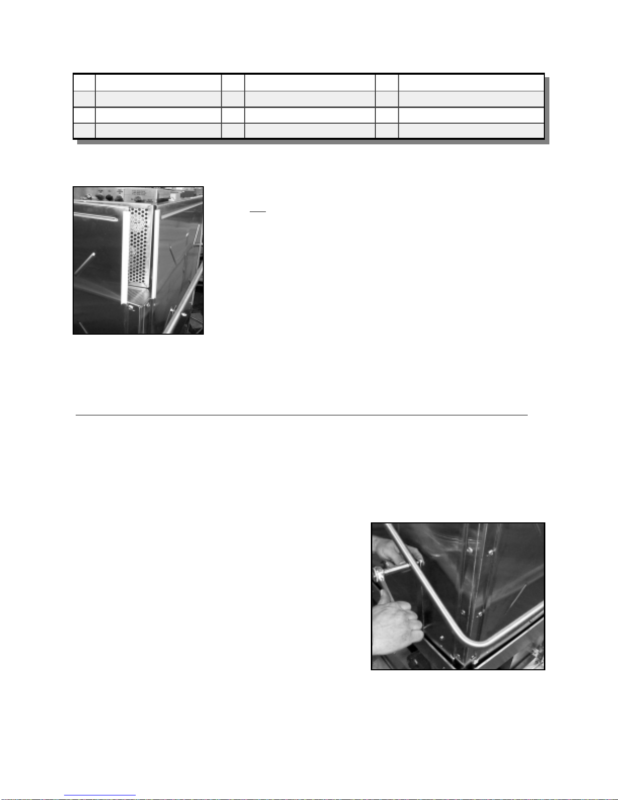
5. Place the dishwasher at the spot desired for
normal operation. Level the dishwasher using
adjustable bullet feet at the bottom of the legs.
Install spray arms included in the accessory box.
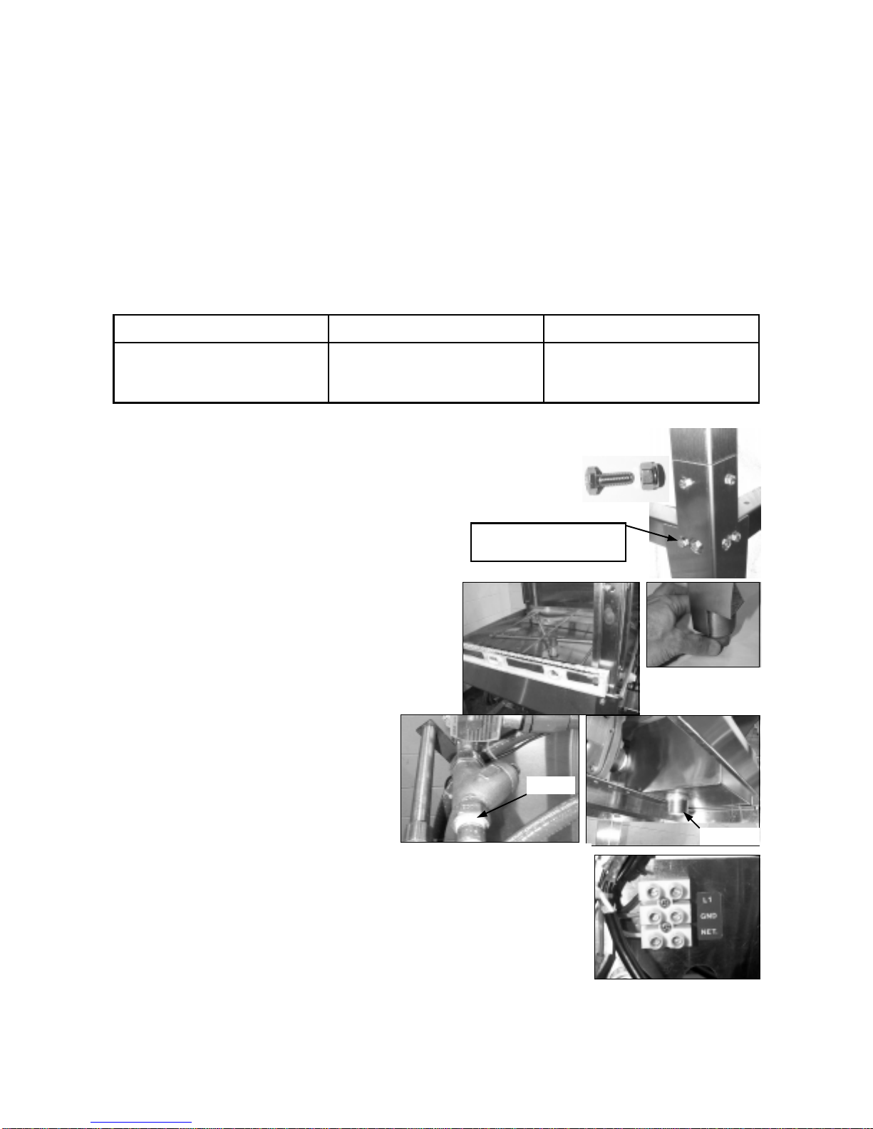
6. Connect hot water supply line to the 3/4 FPT
line strainer at rear of machine. Ensure that wa-
ter pressure is sufficient for fill (approx. 10
GPM flow @ 20 psi.). Connect drain to 1-1/2”
MPT nipple on scrap accumulator.
7. Make electrical connections (refer to data plate for voltage and current ratings)
to the labeled barrier provided at the inside back of the control box. Run all elec-
trical wire through suitable conduit and insure all connections are made in accor-
dance with local wiring codes. It is recommended that the circuit breaker carrying
the dishwasher load have NO OTHER ELECTRICAL DEVICES connected.
8. Attach prewash and drying tables to the dishwasher, insuring that sufficient
space is provided for the dishwasher operator. Insure that adjustable legs on
prewash and drying tables have been adjusted for proper drainage of water.
INTRODUCTION
The KLE 175 GT dishwasher is designed to provide years of excellent warewash results under many types of
conditions. Each unit is configured as an automatic start dishwasher, meaning that the dishwasher starts when
the doors are closed. The dishwasher includes a three product chemical dispenser located on top of the dish-
washer which dispenses liquid detergent, rinse product, and a chemical sanitizer suitable for low temperature
(recommended 140 deg. F applications.) Options and additional features are also available. Contact your near-
est Knight representative for more details.
INSTALLATION - Caution – Access into electrical enclosure must be performed by authorized personnel.
1. Inspect the dishwasher upon initial receipt. Lift the door arm and open the accessory package located inside
the dishwasher. Note that it includes spray arms and other equipment required for installation.
2. Examine the spot where the dishwasher is to be operated. Insure that all electrical and plumbing connections,
as well as dish table placement have been considered for installation. Parameters:
3. Install leg extensions. Each leg requires 4 bolt assemblies, 1/4-20x1/2” long, to se-
cure legs to dish machine. Bolts are located in the accessory kit envelope and on
stand. This job requires two people. Lean the machine back and install two leg
extensions, lean the machine in the other direction and install the other two legs.
Page No. 1
3/4 FPT
1-1/2 MPT
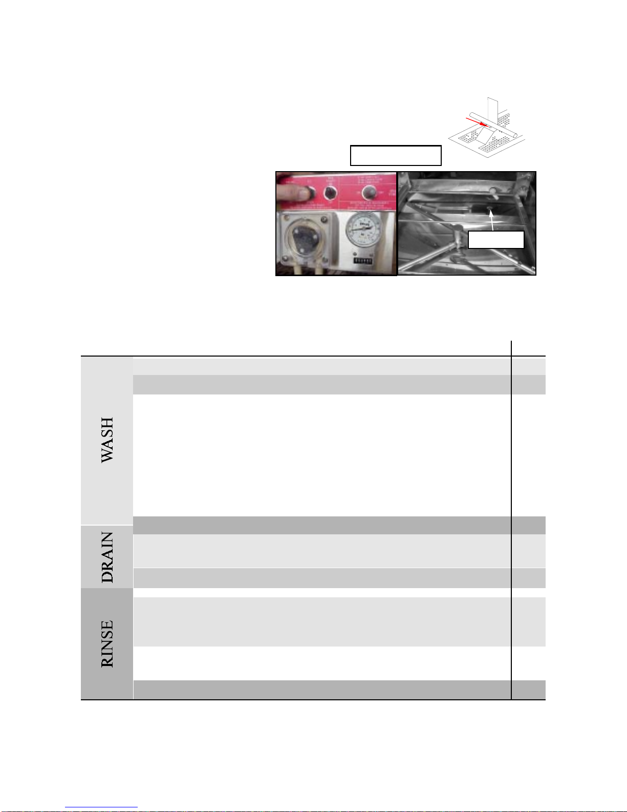
4. Install detergent, sanitizer, and rinse tubing to the peri-
staltic pumps. Use the provided hose clamp ties to secure
delivery tubing to squeeze tubing. Feed outlet tubing to 70
deg. elbow on side of pan directly over the sump. Tubing
installation is easier if done before tabling installation.
Attached to stand, remove and
reinstall to attach legs
(11/10/01) Revision F, EO 4109 Part No. 9641606

Water level
INITIAL OPERATION
1. Check pump intake screen for proper installation.
2. Start with all switches in the OFF position
3. Turn on main power switch. With
doors closed, flip-up the fill button to
fill the dishwasher with fresh 140 deg.
F water (120 F min.). Fill until level
with top of drain ball tube.
4. Turn ON the RUN POWER switch and with doors in closed position the machine will start to wash. Allow
machine to run through one cycle and watch machine sequence through the following wash cycle: (90 second
cycle evaluated ). Machine can be adjusted to 120, 90 or 72 second cycles. See below and page 4 for more de-
tails. (Cycle adjustments will need to be done by authorized personnel only.
1 second – wash pump motor turns on
3 seconds – detergent pump runs for adjusted period of time.
45 seconds – drain opens and machine drains for 15 seconds.
Adjustable 48 to 60 seconds – fresh water valve opens and rinses inside of dishwasher
(drain is still open)
60 seconds – drain closes and fill remains open for period of time to fill dish machine.
70 seconds – sanitizer and rinse pumps run for an adjustable period of time.
70 seconds – wash pump motor stops for three seconds then starts to “burp” the
machine.
90 seconds – machine will stop. This is the end of the wash cycle.
5. Machine is factory adjusted but may need to be adjusted to local water pressure to operate properly.
TIME
0
10
20
30
40
50
60
70
80
90
Page No. 2
Hook tab under rod
(11/10/01) Revision F, EO 4109 Part No. 9641606

TIME SETTINGS
Time settings will need to be done by authorized personnel only. The time settings for detergent pump, fresh water fill,
sanitizer pump, and rinse pump are done inside the control box using the single turn pots. The pots control the time dura-
tion of each of the listed components. Use the chart below to make settings.
POT
CONTROL
ACTIVE TIME
IN 90 SECONDS
SPAN OF POT
TIME
ADJUSTMENT
COMMENTS
Detergent Pump
at time = 3 seconds
2-30 seconds
pot turns from 7 o'clock to 5 o'clock or 10 divi-
sion. Each division is 2.7 seconds. Pump flow is
approximately 1.3 ml/sec.
Sani Pump
at time = 70 seconds
0-15 seconds
pot turns 7 o'clock to 5 o'clock or 10 divisions.
Each division is 1.5 seconds. Pump flow is ap-
proximately 1.3 ml/sec.
Rinse Pump
at time = 70 seconds
0-15 seconds
pot turns 7 o'clock to 5 o'clock or 10 divisions.
Each division is 1.5 seconds. Pump flow is ap-
proximately 1.3 ml/sec.
Fill Start
at time = 48 to 59
seconds
0-11 seconds
fill start is activated during the fixed drain cycle
(45 to 60 seconds) at the 7 o'clock setting time
is 0 and will start fill at 48 seconds in cycle. At
the 5 o'clock setting time is 11 seconds and will
start fill at 59 seconds in cycle. Fill start is set
according to water pressure and the required
time to rinse debris down the drain. Normal
setting at 20 psi flow pressure is 12 o'clock or
5.5 seconds.
Fill Time determined by fill start 10-42 seconds
begins at the setting of the fill start. Once fill
start is set the fill time determines the duration
of time fresh water solenoid valve remains open.
7 o'clock setting time is 10 seconds, 5 o'clock
setting time is 42 seconds. Adjust according to
water pressure. Normal setting at 20 psi flow
pressure is 11 o'clock or 15 seconds.
sanitizer pump pot. rinse pump pot. Fill time pot. Fill start pot.
Page No. 3 (11/10/01) Revision F, EO 4109 Part No. 9641606
Det. Pump pot.
Fuse 1 Amp 250V Fuse 1 Amp 250V Fuse 3 Amp 250V Fuse 2 Amp 250V

JUMPER SETTINGS
Jumper settings will need to be done by authorized personnel only. JP1 and JP2 control the wash cycle time.
Machine is factory set at 90 second wash cycle. Use table below to activate other wash cycles. Turn OFF main
power switch to change cycle times. Adjust Fill time, Fill start and other Pot's for proper operation.
NOTE: JP3 MUST BE CLOSED FOR PROPER OPERATION OF KLE 175GT.
JP3 MUST BE OPEN FOR PROPER OPERATION OF KLE 150GT.
JP4, JP5 and JP6 control proof of chemical delivery. They should be closed if proof of chemical delivery kit (P/
N 7501318 optional) is not installed. Machine can be ordered with proof of chemical delivery kit or kit can be
ordered separately.
PRIME CHEMICAL PUMPS
Each chemical pump can be primed simply by turning the delime switch to “ON” position during run time of
pump in wash cycle. This feature eliminates opening the control box lid to prime pumps using push button
prime switches.
CIRCUIT BOARD PUSH BUTTONS
Circuit board control done by authorized personnel only.
Detergent Push Button- Activities detergent pump if the main power switch is ON.
Sanitizer Push Button- Same as detergent
Rinse Push Button- Same as detergent
NORMAL OPERATION
1. Manually remove food debris from dishes, glasses, cups, etc. The better the pre-rinse the better the wash.
2. Place dishes, glasses, cups, etc. in dish rack. Do not stack dishes. Ensure glasses and cups are placed upside
down.
3. With the run power switch ON, close dish machine doors and machine will start. The wash cycle will take 90
seconds (120 or 72 seconds).
Page No. 4 (11/1001) Revision F, EO 4109 Part No. 9641606
Buzzer
Conn.
detergent
push button sanitizer
push button
JP1 JP2
rinse push
button
JUMPER 72 SEC 90 SEC 120 SEC 360 SEC
JP1 OPEN OPEN CLOSED CLOSED
JP2 CLOSED OPEN OPEN CLOSED
JP4, JP5,
JP6
JP3

9
8
4
6
2
3
3
INSIDE VIEW
remove knockouts
3. The accessory kit supplied with the dish machine contains the door strap and fasteners required to convert
the machine. Table below describes part provided for conversion in this kit.
2. Make sure sump screen is in place over the pump
intake tube so no parts fall in to the pump! Remove
the two knockouts on the front door. One is located in
the center and the other is directly below the right
side door stop bumper. Remove one knockout directly
below bumper on right side door.
Page No. 5 (11/01) Revision F, EO 4109 Part No. 9641606
6
4
2
6
2
9
INLINE OR CORNER DOOR CONVERSION
Conversion from inline to corner can be done by changing the location of the tray stop on the tray rails and install-
ing door conversion bracket and screws in the accessory kit. Two 7/16 wrenches will be needed to make the con-
version.
Conversion of the machine is easier
if done before tabling is attached.
Machines are factory set in the
inline configuration.
1. Remove the two (A) bolts/nuts
securing the tray rail stop located
on the tray rail and reposition to
desired configuration.
2
A
1
1
1
1
5
7

* Provided Hardware.
4. Use the scrap accumulator tray to prop the front door open. Install bracket on
front door first. Use provided bolts, install brass washer against the inside surface
of the door, then spacer, stainless steel washer, and nut on two lower holes as
shown. Use long bolt on upper hole with other existing hardware to secure strap to
door.
5. Remove the nut / bolt assembly on the right side door where bracket will attach. Use the scrap accumulator tray
to prop the front and right side doors open. Install door strap with provided short bolt and other existing hardware
as shown on right side door. -IMPORTANT CAUTION-
The door handle is spring loaded and will rise to open position when handle link is disconnected from the door.
Page No. 6
6. After right and front doors are attached together, (all three doors
will rise when handle is lifted) disconnect left side door link at han-
dle location to disconnect this door from handle assembly. Reinstall
nut / bolt assembly in handle for future use.
No. DESCRIPTIONS No. DESCRIPTIONS No. DESCRIPTIONS
1 P/N 9600421, 1/4” brass washer (4)* 4 P/N 1400462, 1/4-20 nylock nut. (3)* 7 P/N 9660905, Door conn. Strap (1)*
2 P/N 9600430, 5/16 S. S. Washer (3)* 5 P/N 9600423, 1/4-20 x 1/2” long bolt (1)* 8 P/N 9600436, 1/4-20 x 1 1/2” long bolt. (1)*
3 P/N 9600425, 1/4-20 x 3/4” long bolt (3)* 6 P/N 9600819, 1/4” long spacer . (3)* 9 P/N 9640903, Door stop 3/4”
(11/01) Revision F, EO 4109 Part No. 9641606

Page No. 7
If removal of the scrap trap screen is a problem due to space
limitations, the scrap trap can be remounted for front re-
moval. Simply remove the 2 mounting bolts securing the
scrap trap box and slide box towards wash pump motor, lift
drain lifting arm and slide through slit in box.
Remount box as shown, use care not to force box under
drain ball lifting arm...it does not have to be forced.
Use mounting bolts to secure box as shown.
Machine Front
Bolt
Bolt
SCRAP TRAP CONVERSION
(11/01) Revision F, EO 4109 Part No. 9641606

MAINTENANCE SCHEDULE
CAUTION! Before performing periodic maintenance insure water supply valve is turned off and circuit breaker
is on off position.
TASK FREQUENCY PROCEDURE/COMMENTS
Clean fresh water line
strainers
normal - every 2 months
dirty - as needed
clean scrap accumulator
at end of meal time or as needed
clean drain ball and drain
seat
once a day or as needed
wipe with damp wash cloth & detergent
Do not press/wedge drain ball into drain seat.
Set drain ball in place.
clean spray arms
once a day or as needed
remove end caps and dislodge any debris in
spray jets with tooth pick or other pointed
object. Flush length of spray arm with water.
Wipe down outside of
machine and tabling
once a day or as needed
use damp wash cloth and a detergent
Delime inside of machine
as required
use a delime solution as recommended by
manufacturer. Pour solution in machine and
start machine. Flip delime switch on and allow
machine to run for 5 minutes.
Page No. 8 (11/01) Revision F, EO 4109 Part No. 9641606

TROUBLESHOOTING:
PROBLEM CAUSE REMEDY
Low/No spray arm pressure Impeller clogged
Pump intake tube clogged
Spray arm or spray tips clogged
Low water level
*Remove pump face and clean
impeller
*Remove pump face and push
debris out of pump intake tube
Remove spray arm and clean
(see maintenance table
Fill tank to proper level (see
initial operation)
Wash pump motor runs
continuously Delime switch is on.
Faulty circuit board.
Motor relay is stuck
Turn delime switch off
*Call for service
Tap on relay see time setting
section for relay location.
Dish washer will not start Door is open
Run power switch is OFF
No supply voltage
Delime switch is ON
3/8 amp fuse to transformer is
blown
Replace 3/8 amp fuse
Chemical injection bad/poor
(detergent, rinse, sanitizer) Not enough chemical
Poor chemical flow
Faulty chemical pump motor
No chemical flow
*Adjust pot (time settings)
Replace pump squeeze tube
*Replace chemical pump motor
Product container empty
Leaky/noisy vacuum breaker Water pressure too low
Water pressure too high
Clean screen (see maintenance
schedule)
Adjust fill pressure (see
installation)
Reduced wash results Worn spray arm bearing
Washer not level
Tray rails damaged
Replace bearing.
Level with bullet feet (see
installation)
Replace tray rails.
Dish washer will not fresh water fill Faulty solenoid valve
Y’strainer screen clogged
Water supply line is off
Faulty push button fill switch
Fill level not set correctly
*Call for service
Clean screen (see maintenance
schedule)
Open supply valve
*Call for service
See installation section
Dish washer will not drain Faulty drain solenoid
Drain ball jammed in drain seat.
Drain/fill fuse is blown
*Call for service
Open machine and lift drain ball.
Replace 2 amp slo blo fuse
Brown stains inside machine High iron content in water Delime machine to remove
stains. When complete leave
doors in open position to dry
inside of machine.
Page No. 9 * By authorized personnel only. (11/01) Revision F, EO 4109 Part No. 9641606

Page No. 10 (11/01) Revision F, EO 4109 Part No. 9641606

DISCLAIMER
Knight Inc. does not accept responsibility for the mishandling, misuse, or non-performance of the described
items when used for purposes other than those specified in the instructions. For hazardous material information
consult label, MSDS, or Knight Inc.
WARRANTY
All stainless steel components have a three year limited warranty from date of purchase against manufacturers
defects. The electronic control board has a two year warranty. Warranty replacement for component parts pur-
chased by Knight are limited to warranty by the manufacturer. Warranty applies only to the replacement or re-
pair of such parts when returned to factory with a Knight Return Authorization (KRA) number, freight prepaid
and found to be defective upon factory authorized inspection. Bearings and pump seals or rubber and synthetic
rubber parts such as “O“-rings, diaphragms, squeeze tubing, and gaskets are considered expendable and are not
covered under warranty. Warranty does not cover liability resulting from performance of this equipment nor the
labor to replace this equipment. Product abuse or misuse voids warranty.
Page No. 11 (11/01) Revision F, EO 4109 Part No. 9641606

ELECTRICAL BOX
PAGE 13
WRAPPER
PAGE 15
PAN
PAGE 16
STAND
PAGE 18
PLUMBING
PAGE 14
PARTS MANUAL
PUMP
PAGE 17
ACCESSORY KIT
PAGE 19
Page No. 12 (11/01) Revision F, EO 4109 Part No. 9641606

Electrical Box Assembly (Part No. 9640320 120 VAC 60 Hz)
(Part No. 9640320-03 240 VAC 50 Hz)
ITEM PART No. DESCRIPTION QTY LIST PRICE
1 1200392 LOCK WITH KEY (CAM 1200439, SPRING CLIP 1200353) 1
2 9600578 SWITCH RUBBER BOOT 3
3 7507400 TOGGLE SWITCH (ON/OFF) 2
4 9600861 FILL/ DRAIN SWITCH (SPDT) 1
5 7012028 FUSE, 1 AMP, 250 VOLTS. (FILL AND DRAIN SOLENOIDS) 2
6 9600987 BOOT, MAIN SWITCH 1
7 1900679 MAIN SWITCH DPST 1
8 9640328 SWITCH GUARD NEOPRENE 1
9 9640319 COVER 304 SS ASSEMBLY 1
10 9600498-1 POWER REQUIREMENT LABEL 1
11 1200445 CAUTION LABEL ELECTRICAL 1
12 0600311 FUSE 3/8 AMP, 125 VOLTS 1/4 DIA. X 1-1/4 LONG 1
13 0200500 BARRIER 3 POSITION 1
14 9600498 LABEL L1, GND, NET 1
15 2000575 TRANSFORMER TR-3040 1
16 9601975 TEMPERATURE GAGE 1
17 9640356 WELD ASSEMBLY, CONTROL BOX KLE 175 AND 150GT (NO COVER) 1
18 9640327-A REED SWITCH WITH MAGNET (240 VOLT 96403273-A) 1
19 7018096 SQUEEZE TUBE T-53-T (NO PROOF OF FLOW) 3
20 7503453 3-LOBE ROLLER ASSEMBLY BLUE 3
21 7502312 FACE PLATE CLEAR 3
22 7501311 PUMP BODY ONLY 3
23 7010241 40 RPM, 24V DC MOTOR, (7010216, 15 RPM 24V DC MOTOR) 1,(2)
24 7012030 FUSE 3AMP, 250 VOLTS (DRAIN PUMP, OPTIONAL) 1
25 7146000 LTC CIRCUIT BOARD 1
26 7012029 FUSE 2 AMP, 250 VOLTS 1/4 DIA. X 1-1/4 LONG 1
27 9640327-F COUNTER 120 VAC (240 VOLT 96403273-F) 1
Page No. 13
13
24
25
11
6
3 3
1
9
10
4
7
2
14
15
16
26
23
22
21
19
20
18
17
8
12
27
(11/01) Revision F, EO 4109 Part No. 9641606
53

ITEM PART No. DESCRIPTION QTY LIST PRICE
1 9600410 “Y” STRAINER 3/4” FPT 1
2 9600407 1/4” MPT BRASS HOLE PLUG 1
3 9600158 2” HOSE CLAMP 1
4 9640934 PLUMBING BRACKET 1
5 9600510 ELL, STREET 1/2” NPT 2
6 9600549 NIPPLE 1/2” NPT X 1-1/2” LONG BRASS 1
7* 9600551-01 SOLENOID VALVE 1/2” FPT (240 VOLT 9600551-3D) 1
8** 7120102 VACUUM BREAKER 1/2” FPT 1
9 9600022 BRAIDED HOSE ASSEMBLY S.S. 48” LONG 1
10 9600435 ELL 1/2” MPT X 1/2” COMP 1
11 9600358 TEE 1/2” MPT 1
12 9600359 CAP 1/2” NPT 1
13 9501554 BUSHING, 3/4” X 1/2” NPT 1
* 9641907 DIAPHRAGM REPAIR KIT ASCO VALVE -
** 7120102-1 1/2” VAC. BREAKER REPAIR KIT -
Page No. 14
Plumbing (Part No. 9640524 120VAC 60Hz)
(Part No. 9640524-03 240VAC 50Hz)
1
4
3
58
6
7
9
2
(11/01) Revision F, EO 4109 Part No. 9641606
9
10 11
12
13

Wrapper Parts
ITEM PART No. DESCRIPTION QTY LIST PRICE
1 1400462 NUT, 1/4-20 SS W/NYLOCK 34
2 9600834 BOLT, TRUSS HEAD SS 1/4-20 X 5/8” LONG 24
3 9600421 WASHER BRASS .25 I.D. X .562 O.D. 34
4 9600416 SPRING DOOR 1
5 9641313 LINK HANDLE TO SPRING 1
6 9641312 HANDLE ASSEMBLY 1
7 9600436 BOLT, HEX HEAD S.S. 1/4-20 X 1-1/2” LONG 2
8 9600774 WASHER, SPLIT LOCK S.S. 1/4” 4
9 9600437 NUT, ACORN 1/4-20 S.S. 4
10 9600781 FLAT WASHER 1/4 S.S. 12
11 9600819 SPACER BUSHING 1/4” LONG S.S. 2
12 9600843 DOOR PIVOT 2
13 9600641 BOLT HEX HEAD S.S. 1/4-20 X 1-1/4” LONG 8
14 9640903 DOOR STOP NEOPRENE .75” LONG 6
15 9641310 HANDLE PIVOT 2
16 9641309 LINK HANDLE TO DOOR 2
17 9600465-22 DOOR STRIPS 22” LONG 6
18 9600609 DOOR GUIDES S.S. 6
19 9640413 DOOR (right, front, left) 3
20 9640203 WRAPPER WELD ASSEMBLY 1
21 9640204 WRAPPER UPRIGHTS (right and left same part) 2
22 9600835 BOLT, HEX HEAD S.S. 1/4-20 X 5/8” LONG 4
Page No. 15
4
5
15
17
18
19
16
1
3
2
9
8
13
10 12 3
10
11 10
7 8 9
10
1
14
13
1
22
3
20
21
6
(11/01) Revision F, EO 4109 Part No. 9641606

Pan Parts
ITEM PART No. DESCRIPTION QTY LIST PRICE
1 9602148 TRAY RAIL ASSEMBLY 1
2 9660601 TRAY RAIL CONVERTER BAR 1
3 9600423 1/4-20 X 1/2 BOLT (NUT – 1400462 QTY 2) 2
4 9640527 MANIFOLD ASSEMBLY 1
5 9600423 1/4-20 X 1/2 BOLT 2
6 9600437 1/4-20 ACORN NUT 2
7 9600215 SPRAY ARM ASSEMBLY WITH END CAPS 2
8 9602205 SPRAY ARM BEARING 2
9 9600431 THUMB SCREW 3
10 9600417 END CAPS 4
11 9640710 SCREEN ASSEMBLY PUMP INTAKE 1
12 9641515 DRAIN BALL ASSEMBLY 1
13 9640550,9640551,7036070 45 DEG. CHEMICAL INJEC. ELBOW, 3/4” NPT NUT, GASKET EPDM 1,1,2
14 9660105 PAN WELD ASSEMBLY 1
15 9600444-1 DRAIN SOLENOID 120 V 60Hz (240 VOLT 9600454) 1
16 9640944-A and 9640944-B CARRIAGE BOLT AND NUT 10-24 X 1/2 3
17 1900616 8-32 X 5/8 SCREW (NUT 1400461 QTY 1) 1
18 9641516 DRAIN LIFTING ARM GUIDE 1
19 9600641 BOLT 1/4-20 X 1-1/4 LNG (NUT 1400476 , NYLOCK NUT 1400462) 4
20 9641511 DRAIN LIFTING ARM 1
21 9641512 DRAIN SOLENOID COVER 1
Page No. 16
1
2
3
4
5
7
8
9
10
11
12
13
17
6
20
18
21
19
14
15
16
(11/01) Revision F, EO 4109 Part No. 9641606

Pump Assembly (Part No. 9641205 120VAC 60Hz)
(Part No. 9641205-03 240VAC 50Hz)
ITEM PART No. DESCRIPTION QTY LIST PRICE
1 9600008 PUMP MOTOR 1 HP 120 VAC 60 Hz 1
1 9600007 PUMP MOTOR 1 HP 240 VAC 50 Hz 1
2 9600790 1/2” STRAIGHT FLEX CONNECTOR 1
3 9600742 PUMP BASE 1
4 0200252 BOLT, HEX HEAD SS 3/8-16 X 3/4 LONG 4
5 9600748 O-RING FOR PUMP ASSEMBLY 1
6 9600745 PUMP SEAL KIT 1
7 9661202 OPEN IMPELLER 1
8 9600750 PUMP COVER 1
9 0200253 BOLT, HEX HEAD SS 3/8-16 X 1 LONG 4
10 9600478 PET COCK 1/4” MPT 1
11 9640520 PUMP INTAKE TUBE 1-1/2 MPT 1
12 9601605 PUMP DISCHARGE NIPPLE 1” MPT 1
13 9640525 PUMP INTAKE TUBE 1.5 RVT 5.5” CUT 1
14 9601620-D PUMP DISCHARGE TUBE 1.25 RVT 3.5” CUT 1
15 9600158 WORM GEAR CLAMP 2” 4
2
1
3
9
5
6
7
8
10
11
12
13
14 15
4
Page No. 17 (11/01) Revision F, EO 4109 Part No. 9641606

ITEM PART No. DESCRIPTION QTY LIST PRICE
1 9640803 STAND UPRIGHTS 4
2 9600423 1/4-20 X 1/2” BOLT (NUT 1400462 1/4-20 QTY 6) 16
3 9640802 STAND BASE 6
4 9600756 5/16-18 X 3/4” BOLT (WASHER 9600460, NUT 9600889) 2
5 9641405 SCRAP TRAP ASSEMBLY 1
6 9641408 SCRAP TRAY ASSEMBLY 1
Stand Parts
Page No. 18
3
5
6
1
2 4
(11/01) Revision F, EO 4109 Part No. 9641606

ITEM PART No. DESCRIPTION QTY LIST PRICE
1 9641606 INSTRUCTION AND PARTS MANUAL 1
2 9660905 CONVERSION STRAP 1
3
9600425
9600423
9600819
9600421
1400462
9600781
9600436
Bolt 1/4-20 x 3/4 long
Bolt 1/4-20 x 1/2 long
Spacers S.S. 1/4 long
Brass washers
Nuts 1/4-20 with nylock
Washers 1/4 S.S.
Bolt 1/4-20 x 1 1/2 long
2
1
3
4
3
3
1
4 7020182 PICK-UP TUBE 18” X 1/4” 3
5 7028109 TUBING 1/4” O.D. CLEAR 20’ LONG 1
6 9600721 TUBING 1/4” O.D. RED 20’ LONG 2
7 9600722 TUBING 1/4” O.D. BLUE 20’ LONG 1
8 9600431
0300121
NO PART No.
THUMB SCREW 5/16-18
CABLE TIES
CONTROL BOX KEYS
3
6
2
9 1400462
9600423 Nuts 1/4-20 with nylock NOTE: (qty 8 may already be attached to
Bolt 1/4-20 x 1/2 long stand. backwards and loose.) 16
16
10 9600215 SPRAY ARM ASSEMBLIES 2
11 9640806 STAND EXTENSION ASSEMBLY 4
Accessory Kit Parts
Page No. 19
10
1
3
2
4
56 7
9 8
11
11
(11/01) Revision F, EO 4109 Part No. 9641606
Table of contents