manuals.online logo
Brands
  1. Home
  2. •
  3. Brands
  4. •
  5. Knoll
  6. •
  7. Amplifier
  8. •
  9. Knoll GSZ67 User manual

Knoll GSZ67 User manual

Other Knoll Amplifier manuals

Knoll HDMIDA2 User manual

Knoll

Knoll HDMIDA2 User manual

Knoll MA205 User manual

Knoll

Knoll MA205 User manual

Knoll HDMIDA4 User manual

Knoll

Knoll HDMIDA4 User manual

Knoll 4K User manual

Knoll

Knoll 4K User manual

Knoll MA250 User manual

Knoll

Knoll MA250 User manual

Knoll WRA-50 User manual

Knoll

Knoll WRA-50 User manual

Knoll MA252 User manual

Knoll

Knoll MA252 User manual

Knoll MA850 User manual

Knoll

Knoll MA850 User manual

Knoll MX1255 User manual

Knoll

Knoll MX1255 User manual

Knoll KES400 User manual

Knoll

Knoll KES400 User manual

Knoll MR234 User manual

Knoll

Knoll MR234 User manual

Knoll Eco-System GSZ44 User manual

Knoll

Knoll Eco-System GSZ44 User manual

Knoll MX6120 User manual

Knoll

Knoll MX6120 User manual

Knoll MVP64A User manual

Knoll

Knoll MVP64A User manual

Knoll Eco-System CI6 User manual

Knoll

Knoll Eco-System CI6 User manual

Knoll MR171 User manual

Knoll

Knoll MR171 User manual

Knoll GSZ44 User manual

Knoll

Knoll GSZ44 User manual

Knoll MA250 User manual

Knoll

Knoll MA250 User manual

Knoll MX855 User manual

Knoll

Knoll MX855 User manual

Knoll MX1255 User manual

Knoll

Knoll MX1255 User manual

Knoll MA201 User manual

Knoll

Knoll MA201 User manual

Knoll MA225e User manual

Knoll

Knoll MA225e User manual

Knoll HDMIDA8 User manual

Knoll

Knoll HDMIDA8 User manual

Knoll 21K User manual

Knoll

Knoll 21K User manual

Popular Amplifier manuals by other brands

Magnat Audio EDITION FOUR Owner's manual/warranty document

Magnat Audio

Magnat Audio EDITION FOUR Owner's manual/warranty document

Inter-m PA-2000A Operation manual

Inter-m

Inter-m PA-2000A Operation manual

Yamaha TX6n owner's manual

Yamaha

Yamaha TX6n owner's manual

Peavey TNT 150 user guide

Peavey

Peavey TNT 150 user guide

Bosch LBB 1903/10 Installation and user instructions

Bosch

Bosch LBB 1903/10 Installation and user instructions

Avocent Emerge DA1200D Installer/user guide

Avocent

Avocent Emerge DA1200D Installer/user guide

Redgum RGi35 operating instructions

Redgum

Redgum RGi35 operating instructions

Cambridge Audio AXA25 user manual

Cambridge Audio

Cambridge Audio AXA25 user manual

Alpine MRP-M200 owner's manual

Alpine

Alpine MRP-M200 owner's manual

Technical Pro H1502UrBT user manual

Technical Pro

Technical Pro H1502UrBT user manual

FMS EMGZ307 operating manual

FMS

FMS EMGZ307 operating manual

Racal Instruments 5601 user manual

Racal Instruments

Racal Instruments 5601 user manual

Valcom V-1094A Technical specifications

Valcom

Valcom V-1094A Technical specifications

Cambridge Audio 851D user manual

Cambridge Audio

Cambridge Audio 851D user manual

QSC 3800 Specifications

QSC

QSC 3800 Specifications

NAD C300 owner's manual

NAD

NAD C300 owner's manual

Rotel RMB-1077 owner's manual

Rotel

Rotel RMB-1077 owner's manual

Peavey Monitor 300 Series operating guide

Peavey

Peavey Monitor 300 Series operating guide

manuals.online logo
manuals.online logoBrands
  • About & Mission
  • Contact us
  • Privacy Policy
  • Terms and Conditions

Copyright 2025 Manuals.Online. All Rights Reserved.

GSZ67
12 Channel Eco-System™
Controller-Amplifier
Installation Instructions v1.3
2
Important Safety Instructions:
1) Read these instructions.
2) Keep these instructions.
3) Read all warnings.
4) Follow all instructions.
5) Do not use this apparatus near water.
6) Clean only with dry cloth.
7) Do not block any ventilation openings. Install in accordance with the manufacturer’s
instructions.
8) Do not install near any heat sources such as radiators, heat registers, stoves, or other
apparatus (including amplifiers) that produce heat.
9) Do not defeat the safety purpose of the polarized or grounding-type plug. A polarized plug has
two blades with one wider than the other. A grounding type plug has two blades and a third
grounding prong. The wide blade or the third prongs are provided for your safety. If the provided
plug does not fit into your outlet, consult an electrician for replacement of the obsolete outlet.
10) Protect the power cord from being walked on or pinched particularly at plugs, convenience
receptacles, and the point where they exit from the apparatus.
11) Only use attachments/accessories specified by the manufacturer.
12) Use only with the cart, stand, tripod, bracket, or table specified by the manufacturer, or sold
with the apparatus. When a cart is used, use caution when moving the cart/apparatus
combination to avoid injury from tip-over.
13) Unplug this apparatus during lightning storms or when unused for long periods of time.
14) Refer all servicing to qualified service personnel. Servicing is required when the apparatus
has been damaged in any way, such as power-supply cord or plug is damaged, liquid has been
spilled or objects have fallen into the apparatus, the apparatus has been exposed to rain or
moisture, does not operate normally, or has been dropped.
15).Under no circumstances should the output terminals of the amplifier be short-circuited.
16).Be sure that the loudspeakers connected can handle the output power of the amplifier at the
loudspeakers rated impedance. The warranty on the amplifier does not cover damage to
loudspeakers that have inadequate power handling capabilities.
17) A push button is used to turn the power off and on.
18) When the front panel push button switch is in the in position the apparatus is powered on.
CAUTION: These servicing instructions are for use by qualified service personnel only. To reduce
the risk of electric shock do not perform any servicing other than that contained in the operating
instructions unless you are qualified to do so.
Note: The apparatus shall be connected a mains socket outlet with a protective earthing
connection.
Note: Where the mains plug or an appliance cover is used as the disconnect devise, the
disconnect devise shall remain readily operable.
WARNING: This product contains chemicals, including lead, known to the State of California to
cause birth defects or other reproductive harm. Wash hands after handling.
3
FCC Warning
Note: This equipment has been tested and found to comply with the limits for a Class B digital device,
pursuant to part 15 of the FCC Rules. These limits are designed to provide reasonable protection against
harmful interference in a residential installation. This equipment generates, uses and can radiate radio
frequency energy and, if not installed and used in accordance with the instructions, may cause harmful
interference to radio communications. However, there is no guarantee that interference will not occur in a
particular installation. If this equipment does cause harmful interference to radio or television reception,
which can be determined by turning the equipment off and on, the user is encouraged to try to correct the
interference by one or more of the following measures:
•Reorient or relocate the receiving antenna.
•Increase the separation between the equipment and receiver.
•Connect the equipment into an outlet on a circuit different from that to which the receiver is
connected.
•Consult the dealer or an experienced radio/TV technician for help.
Canada
This Class B digital apparatus complies with Canadian ICES-003.
Cet appareil numérique de la classe B est conforme à la norme NMB-003 du Canada.
Caution: To reduce the risk of electrical shock, do not remove the cover (or back).
No user serviceable parts inside. Refer to qualified service personnel.
Warning: To reduce the risk of fire or electric shock, do not expose this appliance to
rain or moisture.
The li htnin flash with arrowhead, within an equilateral trian le, is
intended to alert the user to the presence of uninsulated “dan erous
volta e” within the products that may be of sufficient ma nitude to
constitute a risk of electrical shock to persons.
The exclamation point within an equilateral trian le is intended to alert
the user to the presence of important operation maintenance (servicin )
instructions in the literature accompanyin the appliance.
4
Note: It is very important to use a top quality
RJ45 8/8 crimper tool. We strongly suggest
using a cat 5 / RJ45 electronic tester to verify
the wire conductors.
Introduction:
Thank you for your purchase of a Knoll GSZ67 12 channel
controller amplifier and con ratulations on your choice. The GSZ67 features
six deluxe di ital volume controlled stereo amplifiers with individual seven
source selection. This is Knoll's third eneration of multi-channel, hi h-quality
power amplifiers. The GSZ67 is desi ned to meet the amplifier needs of
custom installed multi-zone systems where hi h quality sound is a specific
requirement.
Each of the six zones or rooms can select any of the seven inputs, with
individual volume control, bass, treble and balance. Extras such as an
external volta e tri er that can turn source equipment on and off, individual
zone infrared outputs, a fully balanced pa in override, RS232 control, fully
buffered line level outputs and many more features ive the GSZ67
exceptional value when installed in homes and lar e complex systems. Except
for the power button all controls are rear mounted. A data port is provided for
an in multiple GSZ67's. Infrared si nals can be relayed from the keypads
to the source equipment.
The GSZ67 is normally controlled by MR164 LCD keypads with or without
Knoll remote controls or RS232 commands from whole house controllers. The
pa in override is normally used for whole house announcements or doorbell
chimes.
 Seven input source selection. Each of the six stereo amplifiers is provided
with seven input source selection. Selection, volume level, bass, treble and
balance is made on MR164 keypads, Knoll remote control (or a pro rammed
remote control) or via an external controller. Rooms can have different
source selections, volumes, etc.
 Six internal 80 position stereo volume controls. The six zones can each
require a MR164 keypad, RB12 remote control or external controller via
RS232. The keypads are typically mounted in the room with the speakers and
they control amplifier power on/off, volume up/down and mute as well as
source selection.
 Cost and size efficiency. The GSZ67 consists of a total of 12 power
amplifiers in one 3-1/2" hi h enclosure (two rack spaces). Each power
amplifier channel can deliver 50 watts RMS with peaks of 100 watts. Because
of its unique desi n the GSZ67 delivers exceptional value.
 Automatic protection circuitry. Each GSZ67 amplifier channel is
individually and fully protected a ainst low impedance, overheatin ,
overloadin , over volta e and under volta e. The protection circuitry
automatically restores the amplifier channel as soon as its parameter returns
to the safe operatin area.
5
 Individual bass, treble and balance adjustment. Each channel features
adjustments so installers can preset the room for speaker differences and
listener preferences.
 External tri er. The GSZ67 can turn on and off source components with
its 12vdc tri er output.
 All zone control. The MR164 keypad features all zone control of all off, all
zones to any one source (then set volume at 1/3) and all zones volume up or
down.
 GSZ67 includes a quiet thermostat controlled internal fan to increase its
lon -term power output capability.
 Infrared controller ports. Each zone or room has its own infrared output
jack. An all zone jack is also provided.
 Zones 5 and 6 have controlled line level outputs so lar er power
amplifiers can be connected to these outputs.
 Optional rack mount version. Occupies two rack spaces.
Unpac ing:
The carton and packin materials used in shippin your new amplifier
were specially desi ned to protect it from the shock and vibration of shippin . We
su est that you save the carton and packin materials to use if you move, or if the
unit ever needs to be shipped back to us for any reason. Should you discover that
your amplifier has been dama ed durin shippin , please contact your dealer or
Knoll immediately and request the name of the carrier so a written claim can be
made.
The ri ht to a claim a ainst a public carrier can be forfeited if the
carrier is not notified immediately in writin and if the shippin
carton and packin materials are not available for inspection by the
carrier. Save all packin materials until the claim is settled.
GSZ67 placement
Durin normal home operation the amplifier will become warm. However, there are
instances durin hi h-level playback into low impedance speakers when the amplifier
will become much warmer than normal. To ensure the amplifier’s trouble-free
operation, it is necessary to provide adequate ventilation. Your amplifier should be
kept away from external sources of heat such as radiators and hot-air ducts. The
amplifier should never be placed with other heat-producin components in a cabinet
or enclosure lackin free airflow. Do not stack other components on top of your
amplifier.
Connecting your amplifier
When makin connections between any source components and the amplifier, or
when makin connections to any speaker, be certain that both the input devices and
the amplifier are turned off. Unplu all equipment before makin any connections so
that there will be no unwanted si nal transients that can dama e equipment or
speakers.
6
Input connections
Connectin the GSZ67 to your source equipment is strai htforward. Usin the hi h-
quality RCA audio interconnect cables, match the output channel desi nations on the
rear of your source equipment to the input jacks on the rear panel of your amplifier
that have the same channel name. When makin connections with RCA type plu s on
interconnect cables, make certain to ently, but firmly, insert the plu into the jack.
Loose connections can cause intermittent sound and may dama e your speakers.
Some quality RCA plu s may be very ti ht, and it is important to secure a proper
connection between the interconnection cable and the input jack.
Spea er connections
The GSZ67 has six stereo 50 watts per channel amplified outputs. Channels 5 and 6
also have line level outputs to connect to lar er powered amplifiers.
To ensure that the hi h quality si nals produced by your amplifier are carried to your
speakers without loss of clarity or resolution, Knoll advises that you use hi h-quality
speaker wire. Many brands of wire are available — the choice may be influenced by
the distance between your speakers and the amplifier, the type of speakers you use,
personal preferences, alon with other factors.
Re ardless of the brand or type of speaker wire chosen, we su est that you use a
wire constructed of fine, multi-strand copper with a au e of 16 or less (the lower
the number, the thicker the cable). Wire with a au e of 16 may be used for short
runs of less than 12 feet. We do not recommend that you use any wires with an AWG
equivalent of 18 or hi her due to the power loss and de radation in performance.
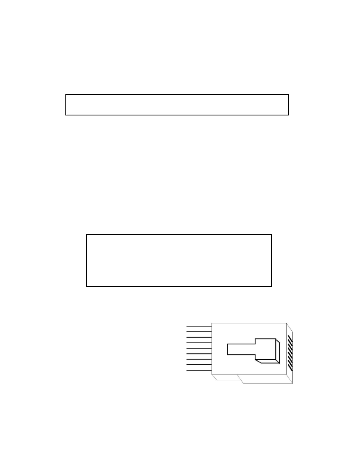
To connect the amplifiers to your speakers, a removable plu with screws is provided for each
stereo channel output. Strip approximately 1/4 inch of insulation from the end of each wire
and carefully twist the strands of each conductor to ether. Be sure not to cut the individual
strands or twist them off. All strands must be used for optimal performance. Insert the wire
into the plu and screw the screws very ti ht. Inspect that no wire “hairs” that can short
circuit are not in the plu .
Correct polarity connections are important to maintain proper speaker phasin . When speaker
phasin is correct, all speakers move in and out at the same time preservin the ima in of
the pro ram material. Out-of-phase connections mean that some turn off, check your
speakers to verify that they are operatin properly. If all other potential sources of trouble
check out properly, contact Knoll for further assistance.
Run the cables to speaker locations. Do not coil any excess cable, as this may become an
inductor that creates frequency response variations in your system. Lastly, connect the wires
to the speakers, a ain bein aware of proper polarity. Remember to connect the ne ative, or
black wire, to the matchin terminal on the speaker. The positive, or red wire should be
connected to the matchin terminal on the speaker.
Note: While most speaker manufacturers follow industry convention of using red terminals for positive
connections and black terminals for negative, some manufacturers may vary from this configuration. To
ensure proper phase connections, and optimal performance, consult the identification plate on our speaker
terminals, or the speaker’s manual to verify polarity. Contact the speaker’s manufacturer if you do not
know the polarity of your speakers.
7
RS232 Connection
The RS232 connection is used to control the GSZ67 by an external controller or
computer and can work with our without keypads. The GSZ67 connects to the RS232
controller with a 9-pin db9 connector. The pro rammin reference follows.
RS232 Terminal Settings
To control the amplifier from a PC environment, connect a standard RS-232 cable
from to a PC or other device (which can run a terminal emulator) to the serial port
on the amplifier. Windows “Hyper Terminal” will be used for examples.
Settin Value
Baud 9600
Data Bits 8
Stop Bits 1
Parity none
Flow control none
Emulation auto detect
RS232 Command Summary
All commands consist of three alpha characters followed by request, all enclosed in
parentheses. The request can be in some cases a read request (followed by a “?”), or
a write request (followed by 0-3 ASCII di its). A read command will return the
current settin , and write command will chan e the settin .
A read request format: (nAA?) where:
( starts the command
n denotes amplifier channel
AA denotes the command
? denotes the read request
) ends the command
Example:
Function Command Response
Volume (1vl?) returns the volume on channel 1 (0-80)
A write request format (nAA###) where:
( starts the command
n denotes the amplifier channel
AA denotes the command
### denotes the value to be written if req’d (leadin zero’s ARE necessary)
) ends the command
Example
Function Command Response
On/Off (1on) turns on amplifier channel one
Select Input (1sl7) selects input channel 7 to amp channel 1
Set Volume (1vl60) selects volume on amplifier channel one to
be set at a value of 60
8
Some commands are read or write only – for example, mute all is a write only
command, whereas version is a read only command.
n = numerical ascii value, where needed (“all” commands do not require)
# = second numerical ascii value
[] = optional command, do not include square brackets in actual command
Function Command Ran e Read/Write
Version (vr?) none read only
Reset (rx) none write only
Channel On (non) n = 1-6 write only
Channel Off (nof) n = 1-6 write only
Mute (nmu) n = 1-6 write only
Unmute (num) n = 1-6 write only
Mute All (amu) none write only
Unmute All (aum) none write only
Vol (nvl [? Or ## ]) n = 1-6 read or write, note 1
## = 0-80
Vol All (avl##) ## = 0-80 write only
Input Select (nsl#) n = 1-6 write only
# = 1-7
Input Select All (asl#) # = 1-7 write only
Bass (nb#) n = 1-6
# = 0-F write only, hex
Treble (nt#) n = 1-6
# = 0-F write only, hex
Note 1: Read on Volume returns decimal value
RS232 Sample Command String
Audio out of Channel 1, Input source 7, Volume = 35, Bass Up, Treble Down, from
“off”.
(1on) turn on channel 1
(1um) unmute channel 1
(1sl7) select input 7 to channel one
(1vl35) set volume to 35
(1ba) turn bass to Hex value “A”, which is Decimal 10
(1t4) turn treble to Hex value “4”, which is also Decimal 4
9
Keypad Connection
The GSZ67 outputs can be controlled by the MR164 keypad and/or an external
controller or computer (usin the RS232 port), so keypads may not be needed.
More than one or two eypads can be used in a zone and nine (9) is the
maximum number of MR164 eypads per GSZ67 allowed.
Note: MR164 keypads are not desi ned for outdoor use, hi h humidity,
hi h temperatures or any extremes.
The MR164 contains an almost all brand infrared repeater and most functions can be
controlled by the Knoll RB12 remote control. RB12 commands can easily be stored in
a learnin remote.
The MR164 is connected to the GSZ67 with CAT5 or CATe wire. Each keypad can
have a home run or be daisy chained on one wire. If you daisy chain one zone
and another zone on one wire you may lose some infrared functionality.
Each room or zone has a unique IR pass-thru port as indicated on the rear of the
GSZ67. In addition there is an all room IR pass-thru port. If you combine two or
more rooms or zones on 1 CAT5 wire the ability to individually split infrared si nals
will be lost. Each keypad has two RJ45 connectors that are both inputs and outputs
for daisy chainin keypads to ether. Five of the ei ht CAT5 wire conductors are
used.
Note: It is very important to use a top quality
RJ45 8/8 crimper tool. We strongly suggest
using a cat 5 / RJ45 electronic tester to verify
the wire conductors.
We recommend the T568A wirin method, which is shown below.
The functions of each wire connection are also shown.
future use brown
future use white/brown
Infrared orange
ground white/blue
+12 vdc blue
future use white/orange
SDA green
SCL white/green
10
Run CAT5 wire from the keypad location to the GSZ67 location for each keypad or
run it from keypad to keypad location. Ideally home runs are used as they leave the
installation more “future proof” and reliable. Leave an extra 1 m or 3 feet on each
side to make it easier to work on. Add a RJ45 connector of the ri ht type for the
CAT5 wire you have selected (not all CAT5 wires are the same) and crimp the
connector to the wire on each side. Plu the RJ45’s into the MR164 and correct
GSZ67 ports.
Note: MR164 eypad installer programming, see MR164
programming near the end of this manual.
Infrared connections
On the rear of the GSZ67 there are seven infrared pass thou h ports. Each of the 1
throu h 6 corresponds to the keypad port next to them. For example IR port #3 is
the infrared output for keypads connected to KEYPAD #3. The infrared ALL is the
combination of all of the 6-keypad ports.
Usin this method of infrared routin you can have six sources the same (like 6
identical AM/FM tuners) one for each zone and they can be controlled individually in
each room. Each port can control up to 8 devices usin 4 of our optional IR34a
emitters and one IR55 connection block.
Each infrared port is a standard 3.5mm mono jack.
DATA IN and DATA OUT connections
On the rear of the GSZ67 amplifier there are two 3.5mm stereo jacks labeled DATA
IN and DATA OUT. These ports connect two or more GSZ67’s to ether so they can
share infrared commands and ALL commands (such as All Off)
When connectin two GSZ67’s to ether in one system you will need:
1. Up to fourteen (one for each active source) RCA patch cords
2. A 3.5mm stereo patch cord.
We do not recommend usin “Y” adaptors in this case. Normally the two GSZ67’s are
near each other. If they are far apart then balancin baluns may be required to
eliminate stray noise on the lines.
The procedure to connect the two controller amplifiers is:
1. Connect the “Data Out” jack on GSZ67 #1 to the “Data In” jack on GSZ67
#2.usin the 3.5mm stereo patch cord.
2. Connect all of the up to seven sources usin short as possible ood quality
RCA patch cords to GSZ67 #1 source inputs.
3. Connect GSZ67 #1 source outputs to GSZ67 #2 source inputs usin ood
quality, short as possible RCA patch cords.
Page Inputs
On the rear of the GSZ67 there is a sin le pa e input on a stereo 3.5mm jack. This
is for connection of external pa in equipment like our DC111 door chime enerator.
The DC111 enerates door chime sounds that are unique for the front, side and rear
doors. These pa in sounds can be heard via the GSZ67 throu hout the home even
if the GSZ67 is switched off or playin some other content.