1. Antes de ensamblar el tubo manija (6), compruebe que la abrazadera (10) se coloque con el agujero para el tubo hacia el motor (Ver fig. C).
2. Deslice el tubo (6) a través de la abrazadera (10), sostenga el yugo (16) en posición vertical e inserte el tubo sobre el yugo (Ver Fig. C)
3. Gire el tubo manija para que el inserto “Clean Freak Industrial” quede hacia el motor, alinée los agujeros del tubo con los del yugo e inserte los dos
tornillos (11) con las cabezas hacia las ruedas (Ver fig. C)
4. Ponga las tuercas de seguridad (12) en los tornillos con la cara plana hacia el tornillo, gírelas manualmente hasta que se pongan duras, luego
sostenga la cabeza con una llave y apriete las tuercas con la otra fuertemente hasta el tope. (Ver Fig. C)
5. Para liberar o fijar la manija solo tiene que girar la perilla de ajuste (8) (ver fig. D)
6. Incline la manija a la altura adecuada para su uso y fije el tubo girando la perilla (8) para apretar.
7. Pruebe la fijación de la manija tirando de ella para inclinar la máquina sobre sus ruedas traseras. Si la abrazadera (10) se desliza sobre el tubo (6)
gire la perilla de ajuste un poco más hasta que la abrazadera no se deslice sobre el tubo al inclinar la máquina. (ver fig. D)
8. Conecte los cables motor (9) asegurándose que los conectores entren completamente uno dentro del otro.
COMO ENSAMBLAR EL TUBO MANIJA
Siempre desconecte la máquina del tomacorriente antes de colocar los cepillos.
1. Desconecte el cable de alimentación, fije el tubo manija en posición vertical y voltee la máquina girándola sobre sus ruedas, hasta que quede
horizontal y con el fondo accesible.
2. Antes de voltear el aparato, coloque un paño o material suave y limpio para recargar la caja manija.
3. Instalar o cambiar el pad. El cojinete debe cambiarse sí el grueso del mismo es menor a 3/8” o menos.
4. Retire el cojinete viejo y coloque uno nuevo centrado sobre el frente con agarre presionando hasta que el pad ya no se caiga.
5. Regrese la máquina a la posición vertical.
6. No opere la máquina sin un cojinete en posición.
7. Siempre deje un cojinete en la máquina para protejer el frente con agarre de cualquier daño.
1. Conecte el cable de alimentación en una toma de corriente aterrizada.
2. Ajuste el tubo manija a una posición cómoda para el usuario y afloje la perilla de ajuste la palanca leva y aprietela a la altura deseada.
3. Oprima el seguro de encendido y al mismo tiempo, oprima la palanca de encendido y entonces encenderá el motor. PRECAUCIÓN: El chasis debe
estar paralelo al piso en el momento de arrancar; si éste se encuentra inclinado, la máquina se desplazará hacia a un lado. Se recomienda que los
primeros intentos se realicen en un área grande en lo que adquiere la experiencia requerida.
4. Si desea apagar la máquina simplemente deje de oprimir la palanca de encendido sin soltar el maneral.
COMO ENCENDER SU PULIDORA
COMO INSTALAR EL COJINETE
Esta unidad funciona con 4 amortiguadores que reducen la vibración de la máquina durante la operación.
Si la unidad vibra o hace más ruido de lo normal, entonces es necesario sustituir amortiguadores.
Para reemplazarlos, siga estas instrucciones:
1. Desenchufe siempre la máquina antes de cambiar cualquier parte.
2. Siga las instrucciones 1 y 2 sobre cómo instalar el cojinete.
3. Quite la parte central de la malla retén, jalándola del porta cojinete.
4. Retire el tornillo central en la parte inferior del portacojinete con una llave española de 3/4 (Fig 1).
Note: Para aflojar el tornillo central, se puede utilizar un destornillador para bloquear el ventilador en la parte superior del motor (Fig. 2) esto
impedirá que el tornillo gire.
5. Retire los 4 tornillos que sujetan con el chasis. (Fig. 3)
6. Destornille los 4 amortiguadores y sustitúyalos con nuevos (Fig. 4)
7. Siga las mismas instrucciones en sentido inverso para volver a montar la unidad.
COMO CAMBIAR LOS AMORTIGUADORES
Fig. 4
1
2
3
4
6Fig. 1
Fig. 2 Fig. 3
Fig. B
Fig. A
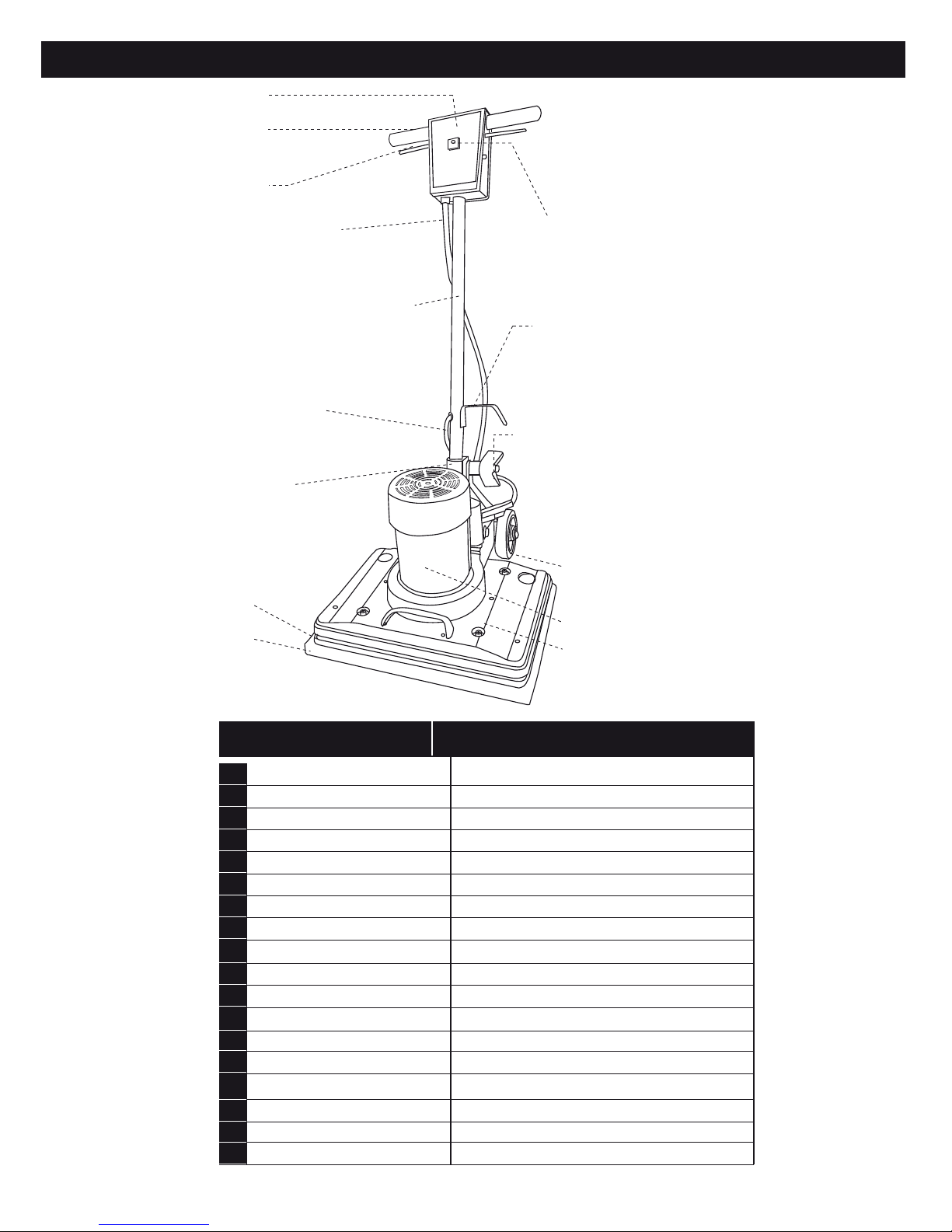
(11) Tornillo
(12) Tuerca
(6) Tubo manija
(10) Abrazadera
(16) Yugo
(8) Perilla de ajuste
aflojar apretar