4C35-VAV 5C35-VAV
1. Introduction
Thank you for purchasing a KOER product. KOER is a brand dedicated to the development and
production of the next generation of hardware and software solutions for HVAC management
and building automation systems. Our vision is to continuously develop and produce quality
products for the building automation industry which will have a positive impact on user
environments, quality of life and, health and safety. With this in mind, we value any insights or
feedback you may have regarding our products. (Email: info@koer.com)
1.1. Use
This device (C35-VAV…) can be used for temperature, air quality and humidity control of
individual zones as part of a Demand Controlled Ventilation system, HVAC system or as a
standalone controller.
C35-VAV… can be used in HVAC systems for:
• Heating
• Cooling
• Ventilation
• Dehumidification
C35-VAV… can control of the following operational elements:
• Damper actuators
• Heat exchange actuators
• Radiator/Floor heating actuator
• Modulating electric heaters
• EC motor fan
1.2. Hardware features
Main hardware features include:
• Resistive Color TFT touchscreen display
• Built-in sensors:
- Temperature
- CO2 (optional)
- Relative Humidity (optional)
• Three analog 0…10 V DC outputs
• One analog 0…10 V DC input
• One analog resistive input
• One binary input
• RS-485 transceiver (optional)
• Galvanic isolated RS-485 transceiver (optional)
• Real Time Clock
• Easy wall mounting
• Power supply 24 V AC/DC
1.3. Software features
• PID control based on temperature, air quality and humidity parameters
• Weekly scheduler, four preset modes, up to eight scheduler timers per day
• Occupied mode function
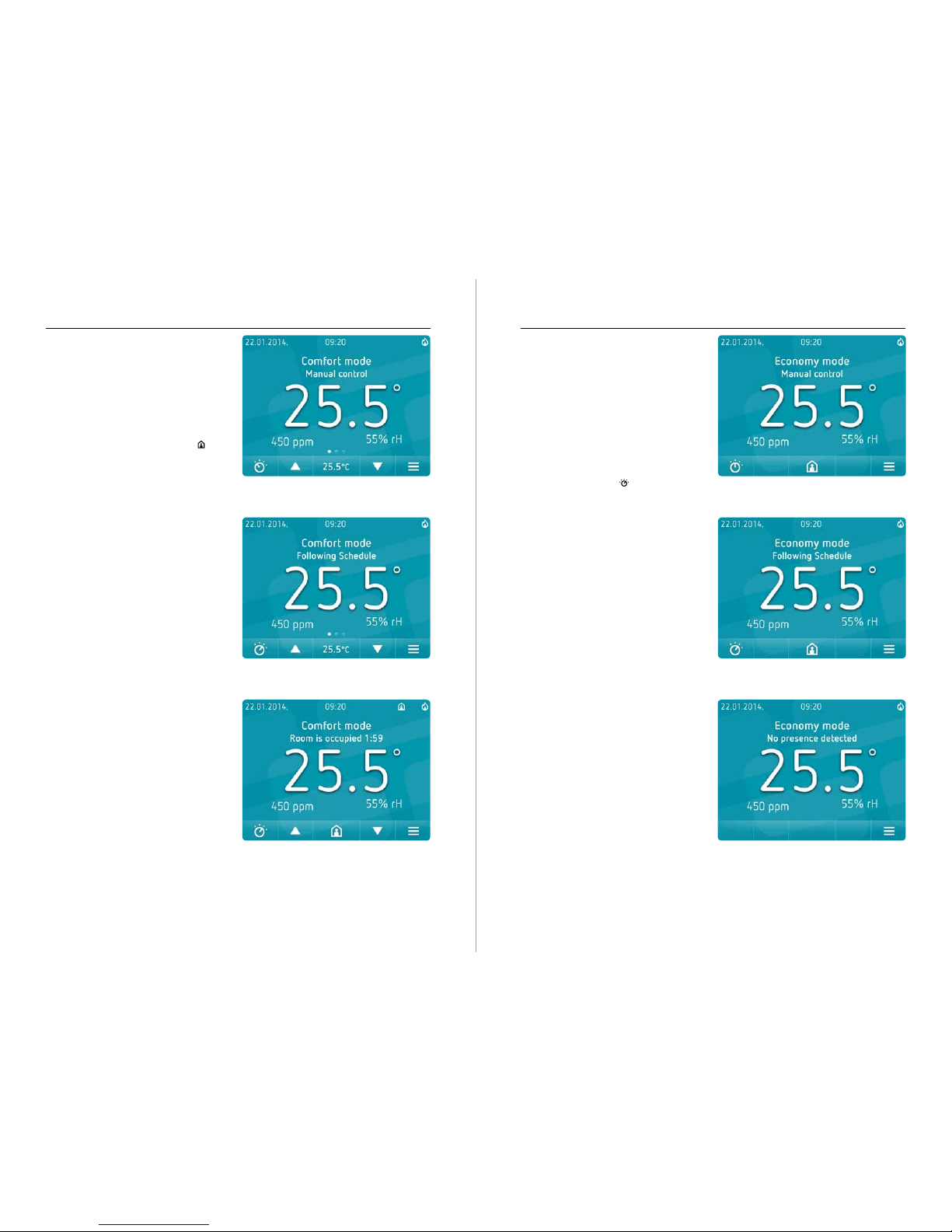
• Three operating modes: Comfort, Economy, Standby
• Protection functionality in Standby mode
• Password protected menu and advanced menu
• Window contact or presence sensor input
• Automatic or manual changeover
• Standby, Dim and Night Mode display brightness
• Easily configurable commissioning and working parameters
• Setpoint limitations for users
• BACnet MS/TP communication protocol (optional)
• Internal Temperature Compensation Algorithm
• Factory Reset function
1.4. Applications
The C35-VAV… was designed for the following VAV applications:
• Single duct
• Single duct with electric heater
• Single duct and radiator
• Single duct with heating and/or cooling coil
Pressure independent VAV applications:
• Single duct with serial fan
• Single duct with parallel fan
• Single duct with serial fan and heating or cooling coil
• Single duct with parallel fan and heating or cooling coil
1.5. Type Summary & Ordering Info
Product
Summary
Inputs Outputs Built in Sensors Protocol Network Interface Enclosure color
0-10V Pt1000 Binary 3x0-10V Temp. Humidity CO2BACnet RS485 Isolated
rs-485
White Black
Option
Codes
-H -C -B /RS /RS-G -BLK
C35-VAV √ √ √ √ √ O O O O O √ O
√ - Available
O - Option
Ordering Code E.g. C35-VAV-C-B/RS-G
Naming
Convention
1) Device 2) Application 3) Options 4) Network Interface 5) Enclosure color
C35 VAV C = CO2 sensor Isolated RS485 White
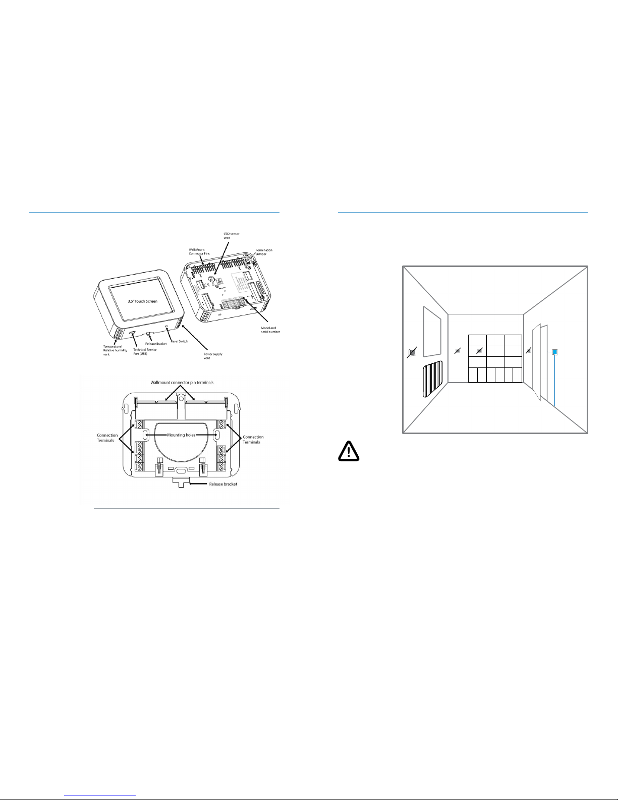
2. Before use or installation
It is strongly recommended that installation is performed by a qualified professional and
that this user manual is read carefully prior to installation. Incorrect installation may result
in malfunction, damaging the device or incorrect configuration. Please ensure you have the
correct user manual for the firmware version as shown on the ‘About’ screen (see page 20).
This manual was specifically written for Firmware Version C35-VAV 1.0.