KOJA HiFEK 18 Technical Document


Roof Extractor HiFEK EC 18-36
Instructions for Transport, Storage,
Installation, Operation and
Maintenance
23.1.2015
Instructions for Roof Extractor HiFEK EC 18-36
Keep this manual near to the Roof Extractor HiFEK for the future need!
Read the manual carefully before taking actions.
Follow the given instructions, especially the safety instructions!
See the separate instructions for electricity, too.
Packing
Roof Extractor HiFEK 18-36 is packed in plastic for transport, storage and relocations on the installation site.
The pack is fastened with binding bands on a wooden pallet. The roof extractor has to be protected from
dust, rain and sunshine at the installation site. Roof extractors must not be piled one on another. The packs
have to be lifted and hauled one by one.
2

Roof Extractor HiFEK EC 18-36
Instructions for Transport, Storage,
Installation, Operation and
Maintenance
23.1.2015
Transport and lifting operations
Follow the instructions for transport and lifting, see the pictures.
Lifting belts and hooks must not be fastened inside the roof extractor.
Be careful not to cause damage to the components when handling the unit.
Lift and move the roof extractor in upright position.
Weights are marked on the packs.
Transport with forklift
Lifting of roof extractor on pallet
Make sure that the lifting forks are as long as
the width of the unit!
Use lifting supports (not included in delivery)
Lift along with pallet!
3

Roof Extractor HiFEK EC 18-36
Instructions for Transport, Storage,
Installation, Operation and
Maintenance
23.1.2015
Lifting lugs (2 pcs)
Use all lifting lugs in lifting.
Instructions for hauling
Roof extractor can be moved by hauling when special caution is observed and provided that
•the side support is ensured to prevent tilting.
•the hauling route is clear and wide enough. The hauling opening and level shall to be wider than the
unit to be hauled.
•the inclination of the hauling route must not cause a change in the centre of gravity and therefore
cause a risk of tilting. Note specially when hauling narrow and high parts.
•the roof extractor is hauled in transport position.
•the carrying capacity of haulage levels is sufficient.
•the roof extractor is lifted with a hauling apparatus.
Safety device and accessories of unit
Safety switch serves also as an emergency stop (accessory).
Guards and stickers fixed at the factory in the unit must not be removed!
CE-marking
Declaration of Conformity of the safety of the unit as well as other documents concerning the operational
safety of the unit is attached to the delivery of the unit.
Fire
In case of fire in the unit, use e.g. powder extinguisher, do not use water. The unit is mainly made of
incombustible materials such as steel and mineral wool.
Lifting lug
Lifting lug
45o
4

Roof Extractor HiFEK EC 18-36
Instructions for Transport, Storage,
Installation, Operation and
Maintenance
23.1.2015
Installation
The roof extractor HiFEK is designed to be mounted outside on the roof of a building, on top of a stack.
Air to be transferred has to be clean and the temperature must not exceed +40°C.
Install the roof extractor to the stack according to the instructions below.
1. The roof extractor is lifted in place by using all lifting lugs. Do not lift the extractor by the outlet
grating or electric cables.
2. Check before mounting that the mounting surface of the mounting stack is straight. Mount the roof
extractor to the stack or existing duct according to the figure below.
3. Install raising rubbers (4 pcs) between the roof extractor and the stack under the every corner
according to the figure so that water gets out of the extractor.
4. The access hatches are opened with a plastic handle attached to delivery or with a hexagon head
wrench or sleeve of 16 mm.
5. Fastening screws (4 pcs) are fixed to the stack from inside when the access hatches have been
removed. Fastening distances: 710mm x 710mm HiFEK 18 and 910mm x 910mm HiFEK 24/36.
5

Roof Extractor HiFEK EC 18-36
Instructions for Transport, Storage,
Installation, Operation and
Maintenance
23.1.2015
Mounting on stack HiFEP
Mounting on wooden duct
Mounting on brick or concrete duct
Hexagon screw M8x55 8.8 FeZn DIN931
Washer 8.4 DIN 9021 FeZn
Rubber cone plug D25/10
Raisin rubber s=10
Seal 15x30
Coach screw M8x80 FeZn DIN571
Washer 8.4 DIN 9021 FeZn
Rubber cone plug D25/10
Raising rubber s=10
Seal 15x30
Coach screw M8x80 FeZn DIN571
Washer 8.4 DIN 9021 FeZn
Rubber cone plug D25/10
Raising rubber s=10
Plastic plug M8
(not included in delivery)
Seal 15x30
6

Roof Extractor HiFEK EC 18-36
Instructions for Transport, Storage,
Installation, Operation and
Maintenance
23.1.2015
Electrical connection
Link box and safety switch are installed on the fixed casing panel.
Connection cables have been marked with colours/numbers. The stack HiFEP is equipped with a cable duct.
Electrical connections, HiFEK 18...36
Carry out the electrical connections according to the instruction.
Roof extractors HiFEK 18-36 are equipped with 3-phase motors. Further information on the connection and
electrical features is found in the separate manual. The standard model always includes a supply cable (W1)
and control cable (W2). The link box is connected at the end of control cable. The supply cable hangs free
and the end has been opened. The connection of the supply cable W1 in 3-phase motors is shown in the
figure below.
The connection of the cable W2 is shown in the figure below. The link box is always included in the delivery.
HIFEK 18-36
Link box
Enable device
7

Roof Extractor HiFEK EC 18-36
Instructions for Transport, Storage,
Installation, Operation and
Maintenance
23.1.2015
Connection marks of motor are as follows:
L1, L2, L3, N: Network access, phase sequency free, (check the voltage in rating plate)
PE: Protective earth
11 and 14: Running indication (n > 200 rpm)
E1: Analog guideline value for rotation speed (0...10 V or PWM)
D1: Digital input, enable device
GND: Voltage reference
10 V: DC output, max. 10 mA
24 V: DC output, max. 70 mA
Ru = Brown
Si = Blue
KeVi = Yellow/Green
Va = White
Mu = Black
Ke = Yellow
Vi = Green
Pu = Red
The motor needs a rotation speed set point for running. It can be formed of the 10V output of the motor. In
cold surroundings the heating of electronics is activated when the inside temperature is -19˚C. That is why it
is very important that the motor supply is never switched off. The motor can be stopped by means of control
or by disconnecting the enable device. To prevent the impeller and motor from freeze-up, it is advisable to
let the motor always run at least at the minimum speed (1.0V control).
If the motor rotates freely e.g. in air flow, it may generate a voltage of more than 50V to connectors.
Rotation of impeller has to be prevented and dead state has to be checked always before service works.
Electornics of motor includes big condencers which may be dangerously live even after switching off the
voltages. Wait at least three minutes after the disconnection of voltage before you start service or repair
works.
Mains voltage must absolutely be the same as given in the rating plate. Motors have integrated overload
protection. Maximum value of fuse for all models is 10A.
Maximum leakage current of the unit is 3.5 mA in mains conforming to the standard DIN EN 60990.
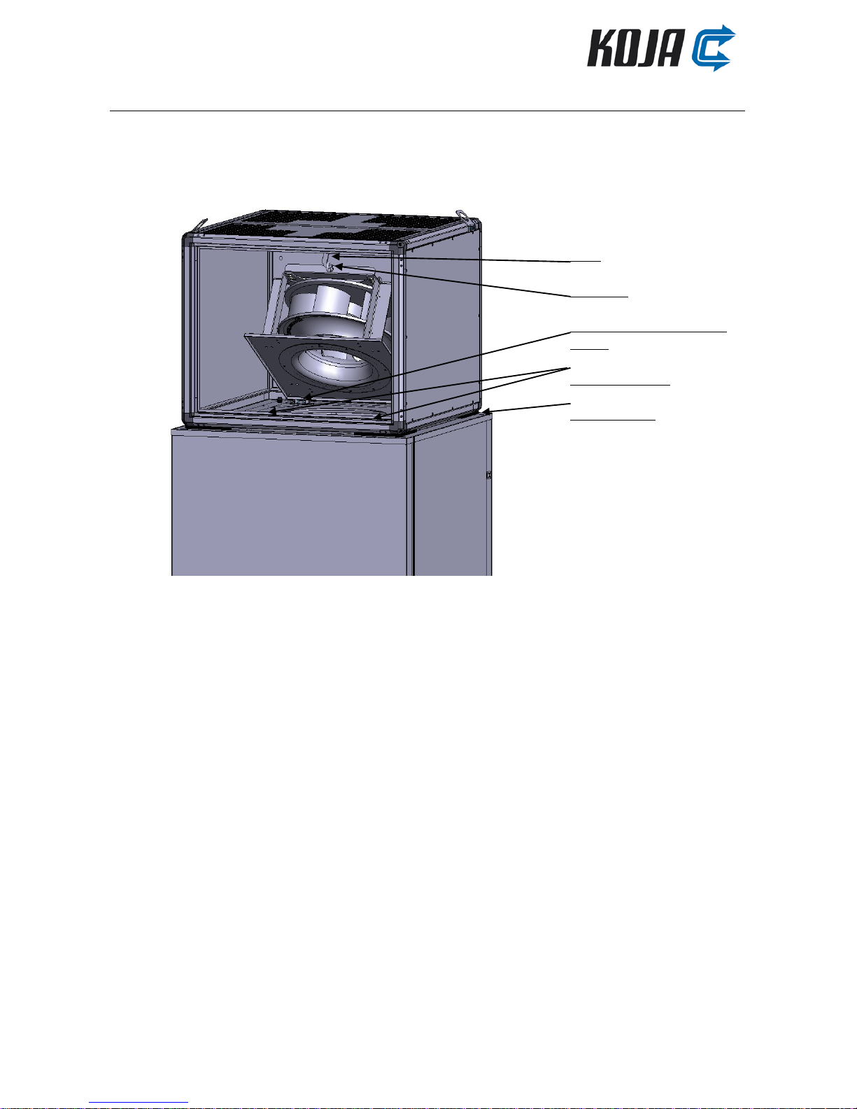
Commissioning and operation
Make sure that the roof extractor has been installed according to the instructions, and that there are no
foreign objects loose inside.
Also check that the electrical connection has been made according to the instructions enclosed in the
delivery.
Make sure that the fastening screws are tight enough in the stack and there is a raising rubber in every corner.
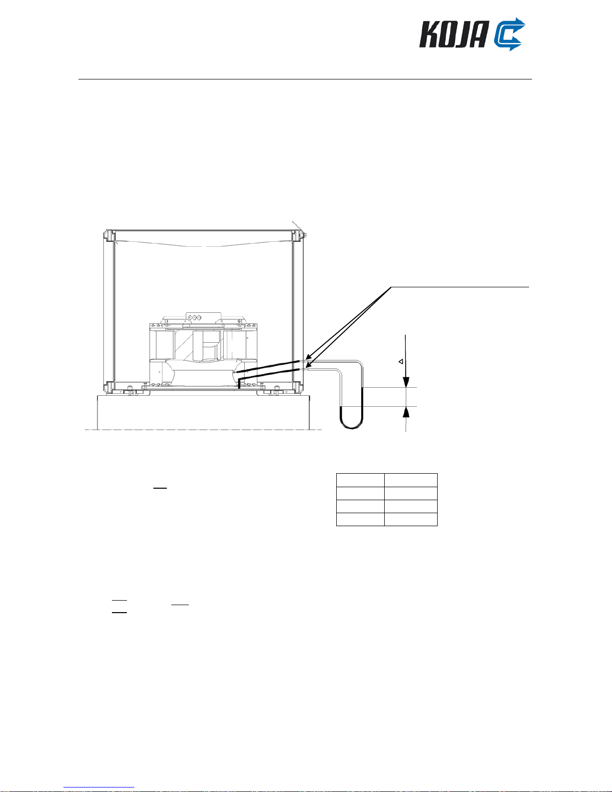
Start the extractor and make sure the impeller rotates in the direction indicated by the arrow marked on the
mounting plate.
Make sure that the base plate is tightly fixed on the mounting surface of the mounting stack.
8

Roof Extractor HiFEK EC 18-36
Instructions for Transport, Storage,
Installation, Operation and
Maintenance
23.1.2015
Maintenance
Turning position of fan
The roof extractor must be inspected and cleaned 1 - 2 times a year.
Before maintenance, use the service switch to make sure that the extractor cannot be started during the
work.
Wait at least three minutes after the disconnection of voltage before you start service or repair works.
Turn the fan for maintenance: Remove two fastening screws of fan, lift the fan and set the hook in the lifting
lug. Make sure that the hook is firmly in the lug.
Have the extractor serviced at the beginning and at the end of the heating season (in autumn and in
spring).
The extractor can be cleaned by the plant’s own service personnel, but services and repairs on the impeller
and motor require special expertise.
Before maintenance of impeller, use the service switch to make sure that the extractor cannot be started
during the work.
Wait until the impeller has totally stopped before starting maintenance works.
Turn the fan for maintenance and cleaning position, see the figure 1. The impeller is cleaned underneath e.g.
with a brush.
Be careful to clean every blade to avoid imbalance in impeller.
Hook
Lifting lug
Fastening screws for hinge
(2 pcs)
Fastening screws
Raising rubber
Figure 1
9

Roof Extractor HiFEK EC 18-36
Instructions for Transport, Storage,
Installation, Operation and
Maintenance
23.1.2015
The motor of roof extractor is prelubricated, no relubrication is needed. In case of bearing malfunction the
entire fan is replaced (available as spare part). The fan is replaced by removing two fastening screws in front
of fan and six hinge screws behind, the fan can then be lifted off.
Weight of roof extractors: HiFEK 18 32kg
HiFEK 24 59kg
HiFEK 36 69kg
Measuring of air flow
Calculation of air flow volume:
HiFek
k-factor
18 EC
0.0547
24 EC
0.0856
36 EC
0.1058
qv[m3/s] = k *
where Δp is pressure difference of measuring
connections [Pa]
If operating temperature differs from +20⁰C, following formula is applied:
qv=
*
*
where
is air density in operating temperature and
= 1,20 /
Measuring connection of air flow
P
10

Roof Extractor HiFEK EC 18-36
Instructions for Transport, Storage,
Installation, Operation and
Maintenance
23.1.2015
Check list in case of malfunction
Switch off the roof extractor before checking, open the access hatches and lift off. Wait at least three
minutes after the disconnection of voltage before you start service or repair works. The roof extractor may
be turned aside on the clasp if it is needed to check the stack. Sequence codes of motor LED and state signal
are in the separate electricity manual.
1. The roof extractor vibrates: Check,
•that there are no ice or impurities in the impeller causing imbalance.
•that there is no obstacle in the ducts or on the unit restricting the air flow.
•that the dampers of the stack are operating properly.
•that the fastening screw of the impeller is fixed and tightened.
•that the blades of impeller are undamaged.
•that there are no loose balancing pieces.
2. The unit operates but the rates do not correspond those given in the data sheet: Check,
•that the impeller rotates in the right direction (arrow in the motor mounting plate).
•that the valves are open.
•that all air terminal devices have been installed.
•that the dampers are open.
•that the pressure loss of the ductwork is not bigger than estimated.
3. The extractor does not start: Check,
•that the fuses (and eventual thermal relays) are undamaged and correctly dimensioned (max. 10A).
•that there is voltage in the motor and that voltage is in all phases (shall absolutely be same as in
rating plate!).
•that control voltage is above the starting limit (1V).
•that the enable device has been connected (control connection of motor D1).
•that the connection is correct (see chapter "Electrical connection").
•that the impeller rotates freely. (Ice or some mechanical object may restrain the rotation.)
4. There is a strange noise in the extractor: Check,
•that the impeller rotates freely. (Ice or some mechanical object may restrain the rotation.)
If the roof extractor does not operate properly in spite of these acts, write down
•the unit code: e.g. T41400348WL
•the order number: e.g. 901371 / 1001 / 10
shown in the type plate and
contact Koja: Contact information www.koja.fi
NB. We check all products returned. If the return is unfounded, we shall charge the price of the substitute
product we sent.
Liability for faults and defects according to the general conditions of Koja Ltd, see www.koja.fi/
Air handling/Price list.
11
This manual suits for next models
2
Table of contents