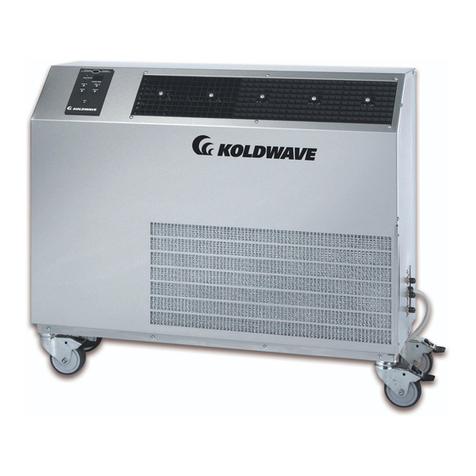
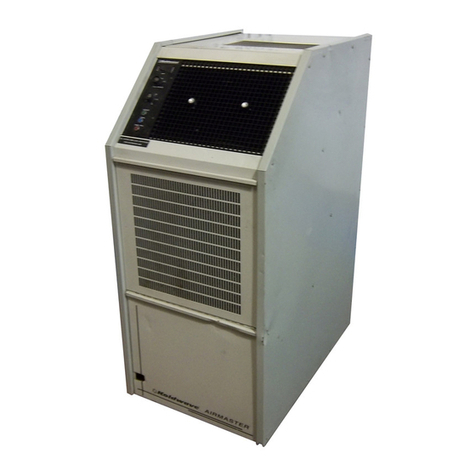
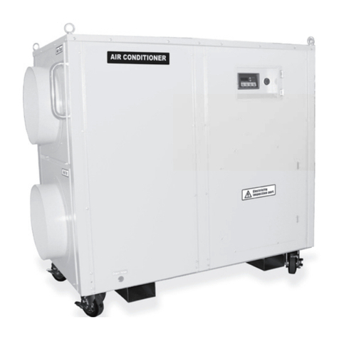
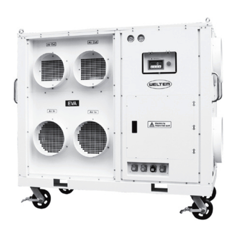
Koldwave KWV-20 Manual instruction

KWV-20G*ATA**
REV — 02/26/20
Portable Air Conditioners
Model KWV–20
SETUP, OPERATION, AND MAINTENANCE MANUAL
20 TON PORTABLE VERTICAL AIR CONDITIONING UNIT
260 North Elm St. Westeld, MA 01085
Phone: 413-564-5520 Fax: 413-564-5815
www.koldwave.com

Subject to change without notice. 2KWV-20G*ATA**
REV — 02/26/20
IDENTIFICATION OF YOUR PORTABLE UNIT
The Data Tag contains important information
on how identify your Koldwave Unit.
See Figure 1 for more information on locating tag.
MODEL NO. HKW30G3ATA60-TR
SERIAL NUMBER 1610057
VOLTS 208/230 PHASE 3 CYCLE 60
COMP. LRA 351 EA QTY 2 RLA 53.6 EA
EVAP. MOTOR HP 15.0 FLA 35
COND. MOTOR HP 3.0 EA QTY 2 RLA 8.6 EA
ELEC. HEATER KW 60
MCA 240.8
MOP 250
FACTORY CHARGE R-410A 46 lb 0oz CKT1
46 lb 0oz CKT2
TEST PRESS. HISIDE 500 PSIG - LOSIDE 250 PSIG
COMPRESSOR MOTOR AND FAN ARE THERMALLY PROTECTED
USE COPPER CONDUCTORS ONLY.
EXT. STATIC PRESS - 0.1 TO 1.0 IN. WC.
MAX OUTPUT AIR TEMP. 200 DEG. F OR LESS
MIN. CLEARANCE TO COMBUSTIBLE SURFACES - 0 IN
9CA-6242
UNITED COOLAIR CORPORATION
YORK, PA
Sample
Koldwave

Subject to change without notice. 3KWV-20G*ATA**
REV — 02/26/20
WARNING: HIGH VOLTAGE – DISCONNECT POWER BEFORE SERVICING
DISCONNECT POWER
Failure to disconnect power before
servicing could lead to severe
personal injury or death.
RE-CONNECT ALL GROUNDS
All parts of this product capable of conducting electrical current
are grounded. If grounding wires, screws, straps, clips, nuts,
or washers used to complete a path to ground are removed for
servicing, they must be reconnected at their original location.
TABLE of CONTENTS
IDENTIFICATION OF YOUR PORTABLE UNIT.................................................2
SPECIFICATIONS........................................................................4
INSPECTION OF EQUIPMENT .............................................................5
MOUNTING THE EQUIPMENT .............................................................5
INSTALLATION OF UNITS.................................................................5
OPERATING INSTRUCTIONS ..............................................................5
CONTROLS ............................................................................6
UNIT COMPONENTS .....................................................................7
MAINTENANCE .........................................................................7
REFRIGERATION SYSTEM COMPONENTS ..................................................8
ROUTINE MAINTENANCE.................................................................9
TROUBLESHOOTING GUIDE .............................................................11
DRAWINGS AND SCHEMATICS
Wiring Diagram: CA6176P11*
Product Drawing: CA3127 (H)*

Subject to change without notice. 4KWV-20G*ATA**
REV — 02/26/20
SPECIFICATIONS
COOLING MODE
Entering Air Dry Bulb ............................................................................................................................................................................80°F
Entering Air Wet Bulb ............................................................................................................................................................................67°F
Outdoor Ambient....................................................................................................................................................................................95°F
Total ......................................................................................................................................................................................... 250, 840 Btuh
Sensible .................................................................................................................................................................................. 170, 620 Btuh
Operating range........................................................................................................................................................................ 65°F – 115°F
POWER REQUIREMENTS
Voltage / Phasing / Frequency.................................................................................................................................................208/230-3-60
Minimum Circuit Ampacity .........................................................(Amps) ............................................................................................ 106.4
Maximum Overcurrent Protective Device................................................................................................................................................ 125
COMPRESSOR
Quantity / Type .................................................................................... 2............................................................................................. Scroll
Voltage / Phasing / Frequency.................................................................................................................................................208/230-3-60
RLA ............................................................................................(Amps).............................................................................................. 35.2
LRA ............................................................................................(Amps) ............................................................................................... 250
CONDENSER BLOWER MOTOR
(Quantity) / Horsepower ........................................................Quantity 2............................................................................................... 5 hp
Voltage / Phasing / Frequency .......................................................................................................................................................208-3-60
FLA ............................................................................................(Amps)............................................................................................. 13.6A
Design Condenser Air Flow ..................................................................................................................................................... 12,400 CFM
EVAPORATOR BLOWER MOTOR
Horsepower ......................................................................................................................................................................................... 5 hp
Voltage / Phasing / Frequency........................................................................................................................................................208-2-60
FLA.............................................................................................(Amps)............................................................................................. 13.6A
Evaporator Design Air Flow ....................................................................................................................................................... 8,000 CFM
REFRIGERANT
Compressor 1 .......................................................................... R-410a ............................................................................................25 lbs.
Compressor 2 .......................................................................... R-410a ...........................................................................................25 lbs.
Low Pressure ...............................................................75 PSIG Cutout ................................................................................... Auto Reset
High Pressure.............................................................650 PSIG Cutout................................................................................ Manual Reset
Suction Operating Pressure ...........................................25 PSIG Low 1............................................................................... 45 PSIG High1
Discharge Operating Pressure ........................................90 PSIG Low1............................................................................. 300 PSIG High1
Superheat ................................................... @ approx. 80 °F ambient ............................................................................................. 15°F1
Subcooling ................................................... @ approx. 80 °F ambient ............................................................................................. 10°F1
DIMENSIONS AND WEIGHT
Height/Width/Length......................................Refer to Product Drawing................................................................................ See Appendix
Weight .............................................................................................................................................................................................2250 lbs.
*Readings are dependent upon ambient conditions; numbers listed are approximate

Subject to change without notice. 5KWV-20G*ATA**
REV — 02/26/20
INSPECTION OF EQUIPMENT
Upon receipt of unit, inspect for visible or
concealed damage. Report any damage to the
carrier and le a damage claim.
MOUNTING THE EQUIPMENT
The unit is a self-contained air cooled system. It
should be mounted on a level surface.
INSTALLATION OF UNITS
The standard conguration of the portable vertical
unit is shown in Figure 1 - Standard Portable.
1. The unit shall be shipped as a single pack-
aged unit.
2. The unit is fully charged with R410A when
shipped.
3. The unit is provided with forklift pockets at the
bottom for moving the unit to the desired loca-
tion for installation.
4. Connect the condensate drain line for the unit.
A “kazoo” tube is shipped loose with the unit.
Run hose from the condensate drain connec-
tion to the desired condensate disposal loca-
tion and attach the “kazoo” tube to the end of
the hose.
NOTE: The “kazoo” tube acts as a condensate
trap and is required.
5. Refer to the unit data plate for main power re-
quirements. Electrical wiring and grounding
must be installed in accordance with the latest
revision of the AS/NZS 3000 standard. Route
the incoming power to the unit’s main power
connection. Make sure the power supplied
to the unit matches the unit power require-
ments for this unit.
Figure 1 – Standard Portable
6. Install the tent material under the tent clamps
on each side of the cabinet. A 7/16“ wrench is
required to loosen the bolts securing the tent
clamps.
NOTE: Do not over- torque tent clamp bolts.
OPERATING INSTRUCTIONS
Before electrical power is applied to the unit, make
sure the unit is connected to an earth ground. The
circuit breaker should be in the “OFF” position.
Electrical power is supplied to the unit from a
power source (shore power or generator) via a
connecting cable, which terminates in the factory
supplied power connection. Connect the main
power wires to the power connectors. See Figure
2 – Power Input Location. This supplies power to
the entire unit. Make sure that the power that will
be supplied to the unit matches the electrical data
label provided in the unit.

Subject to change without notice. 6KWV-20G*ATA**
REV — 02/26/20
Figure 2 – Power Block Location
Internal wiring connects the incoming power to
a circuit breaker, which also serves as a service
disconnect switch. Switching the breaker to the
“ON” position supplies power to the unit.
Once the power is turned “ON”, proper sequencing
of the three phase power input will be indicated by
the lighting of the Phase Indicator Lamp (PIL). If
the lamp is lit, change any two of the conductors
(excluding the ground wire) at the power source.
Do not change wiring internal to the unit! This unit
will not run unless the phasing is correct.
CONTROLS
Toggle Switch TS1 – Blower Control:
When Toggle Switch TS1 is set to the ON position,
the Supply Air Blower will operate continuously.
At this point the system must be controlled using
either manual control or by the use of a thermostat.
Selector Switch 1 (SS1)
(Selection for Manual Control of Heat or Cool
Modes)
The Selector Switch 1 (SS1) is used to select
the desired manual control mode for the unit.
Set the selection to Thermostat Control when
the Thermostat shall be used to control the
conditioning of the air. Select Manual Cool when
1 to 2 stages of Manual Cooling is/are desired.
Select Manual Heat when 1 to 2 stages of Manual
Heating is/are desired. If Manual Cool or Manual
Heat is selected, the appropriate switch must then
be used to control the desired number of Heating
or Cooling Stages desired.
NOTE: A time delay is built into the system to
prevent Stage 1 and Stage 2 compressors
from energizing simultaneously if two
stages are desired to operate at the same
time. This time delay is set to 5 minutes.
Figure 3 - Thermostat
Thermostat Operation – Unit Mounted:
1. Set Selector Switch SS1 to the desired mode
of operation (COOL or HEAT).
2. Set the thermostat settings on the Penn A28
thermostat (see Figure 3 – Thermostat) to the
desired temperature setting. Turn the Tem-
perature dial to the desired temperature set-
ting.
3. Stage 1 and Stage 2 cooling or heating will op-
erate based upon the thermostat setting and
the mode selected in Step 1.
When the space temperature rises approximately
1° F above the setting the system will turn “ON”.
The differential between stages is approximately
2° F. The equipment will not cycle more than 6
times per hour in the cooling mode.
Mode
Switch
208-3-60
Phase
Reversal
MCA 78.8
Optional
Hour Meter
Thermostat

Subject to change without notice. 7KWV-20G*ATA**
REV — 02/26/20
UNIT COMPONENTS
Optional Deection Registers
The supply grilles are divided into 2 rows of
manually adjustable louvers.
The horizontal louvers are in the front row. These
are individually adjusted by hand.
The vertical louvers are the second or back row.
Each section has a louver adjustment tab. The
tab will adjust the vertical louvers as a section and
can be moved with your nger.
Optional Hour Meter
The unit may be equipped with an optional
hour meter. This meter indicates the cumulative
operating time of the system.
Sight Glass
Each refrigerant circuit has a sight glass to
determine that a liquid seal of refrigerant exists
going to the expansion valve.
The sight glass also has a moisture indicator to
detect the presence of moisture in the refrigerant.
The indicator is yellow if moisture is present and
green in color if there is no moisture.
If bubbles appear in the sight glass, the system is
either undercharged with refrigerant or there may
be a restriction in the liquid line upstream of the
sight glass.
NOTE: Bubbles will occur for a minute or two
when the compressor system starts.
Bubbles will also be present during low
ambient operation or on the 20-ton unit
circuit 1 when the hot gas bypass is
activated. Do not add charge to overcome
bubbles for these reasons.
Access Fittings
Each refrigerant circuit is provided with Schrader
type access ttings. These can be used to adjust
the refrigerant charge if necessary.
Air Flow
The units are provided with an air proving switch.
If air ow is not detected, the unit will not allow
the cooling circuit to function. This protects in the
case of a motor or belt failure.
Pressure Switches
Each refrigerant circuit is provided with a High
and a Low pressure switch. These are automatic
reset type.
These units contain lockout relays that activate
when the pressure switch(s) open the circuit. The
main power to the unit must be switched Off and
then On to reset the lock out relays
CAUTION: Unit power should be turned off
when doing any work on the unit
when one or both of the pres-
sure switches has been opened.
Unit may start when the pressure
switches automatically reset, thus
causing a hazard to the service
personnel.
Hot Gas Bypass
20-ton units have a Hot Gas Bypass valve on
System 1. This valve helps keep the system
running when the space load drops. It functions
by articially loading the evaporator with some hot
discharge gas from the compressor into the inlet
of the evaporator.
MAINTENANCE
Bearings
Motor and Blower bearings are permanently
lubricated and require no maintenance.
Belts
The condenser and evaporator blowers are belt
driven and are provided with adjustable sheaves
to change the speed. The drive belts should be
examined periodically for wear and for correct
tension. If the belts are too tight it can cause

Subject to change without notice. 8KWV-20G*ATA**
REV — 02/26/20
bearing wear and a loose belt can cause slippage.
If the two legs of the belt are pressed in, midway
between the pulley and the sheave, and results
in 1” to 1-1/2” of movement, the belt is tensioned
properly. Belt tension can be adjusted by means
of the adjusting bolt, which requires loosening a
nut to move the motor to change belt position.
Filter Maintenance
If the unit has disposable lters, inspect at least
once a month and change as required. Access to
the disposable lter is gained through the return
air grille.
The unit may also contain optional cleanable
lter(s) installed in the evaporator return air
section. The return air grille must be removed to
gain access to the lters. Check lters every few
weeks to verify that the lters are clean.
After a period of use, dirt, lint, and the original water
soluble adhesive coating are easily removed by
simply ushing the lter in a stream of water.
Apply a new coating of adhesive, such as RP Super
Filter Coat, to restore the lter characteristics.
FRESH AIR DAMPER - OPTIONAL
This unit is supplied with an optional fresh air slide
damper. The fresh air is introduced AFTER the
DX coil, and is not conditioned.
refrigerant pressures. If the refrigerant pressure
falls below 70 PSIG, the switch will open causing
the compressor to shut off. As the pressure starts
to rise above 100 PSIG, the switch will reset and
allow the compressor to restart.
Thermostat
The unit has a digital thermostat for one stage
of cooling refer to the appendix at the end of the
manual for operating instructions.
Time Delay (TD) – Compressor Short Cycling
Single Phase units have a time delay relay that
delays the start of the compressor for 5 minutes
when there is a call for cooling. Each single phase
unit must have a time delay relay for compressor
short cycling to prevent immediate restart after a
brief operating period. If the compressor tries to
restart due to constant space loading, mechanical
loading due to un-equalized refrigerant system
pressure would prevent the compressor from
operating and over a period of time, could cause
premature failure of the compressor. When the
compressor becomes mechanically bound due to
un-equalized pressures, the motor windings heat
up which cause the compressor to trip on thermal
overload.
REFRIGERATION SYSTEM COMPONENTS
Compressor
The compressor is scroll hermetic type. The
function of the compressor is to create a
differential in refrigerant pressure. It converts
low pressure, low temperature refrigerant vapor
entering the suction side of the compressor into
a high pressure, high temperature gas at the
discharge side of the compressor. The function
of the compressor also pumps the refrigerant
through the piping and components within the
refrigeration system.
Condenser Coil
The condenser receives the high-pressure high-
temperature gas from the compressor after it
passes through the vibration eliminator. As the
condenser blower draws the ambient air across
the ns and tubes of the condenser coil and
the high-pressure high-temperature gas enters
the condenser coil, the gas starts to condense
back into liquid state. At the outlet piping of the
condenser coil, the gas has been turned back into
liquid refrigerant and ows toward the receiver.
Evaporator Coil
As the liquid refrigerant passes through the
expansion valve, the liquid refrigerant’s pressure
is regulated downward. This signicant change
Subject to change without notice. 9KWV-20G*ATA**
REV — 02/26/20
in pressure causes a drop in temperature of
the refrigerant. When the warmer ambient air
is drawn over the cooler evaporator coil, the
warmer or latent heat is exchanged. As the heat
is being exchanged, the exchange of heat energy
causes the liquid refrigerant to boil into a vapor
and greatly reducing the temperature of the air on
the outlet side of the coil. The liquid refrigerant
is converted into the lower temperature, lower
pressure refrigerant causing it to changing into a
vapor state.
Filter Drier
The lter drier, lters loose particles, moisture and
possible brazing residue from the system. If the
unit starts tripping on low pressure cutout and the
refrigerant line is frosted up to the outlet of the
lter drier, check the refrigerant pressure drop
across the lter drier and replace the lter drier if
necessary.
Sight Glass
A liquid sight glass is located before the liquid
line solenoid valve. During the cooling mode of
operation, pure liquid should ow through the
liquid sight glass. The liquid refrigerant will appear
clear enough to see the back of the inside of the
sight glass. Flashing (bubbles) will appear in
the sight glass during the rst minute or two of
operation until the expansion valve fully adjusts.
If ashing is constant during the cooling mode, it
may be an indication the unit is short of refrigerant.
There may also be some ashing during hot gas
bypass operation. See the Troubleshooting Chart
for further details.
Thermostatic Expansion Valve
The expansion valve regulates the amount of
liquid refrigerant entering into the evaporator. As
the liquid enters into the expansion valve, the
valve will start to change the state by changing
the pressure of the liquid refrigerant as it passes
through and starts to enter the evaporator coil.
When the environments load conditions start
to change, the bulb recognizes a change in
temperature at the outlet piping of the evaporator
to the suction side of the compressor and
automatically adjusts the valve to maintain the
correct ow into the evaporator coil.
ROUTINE MAINTENANCE
To keep the Portable Air Conditioner unit
operating safely and efciently, it is recommended
that a qualied service technician check the
entire system at least once a year. Check the
system more frequently depending on use and
surrounding conditions.
Filters
It is very important to keep the air lters clean.
Be sure to inspect them at least once each month
when the system is in constant operation. The
PAC4 unit typically has a cleanable air lter.
Remove the lter and use a brush to brush caked
on dust from the lter. Next, use a stream of warm
water to rinse remaining dust from the lter then
reinstall.
If the unit is equipped with disposable type air
lters, replace them with the same type and size.
NOTE: Do not attempt to clean disposable air
lters.
Condenser Coil
Inspect the condenser coil. If the condenser coil
is dirty, clean with a stream of cold water, and
pressurized air not exceeding 50 psig, or vacuum
cleaner. Do not use hot water or steam, which can
cause excessive high pressure in the refrigerant
system. Clean the condenser coil in the opposite
direction of the airow.
Blower and Motor Drive Components
The Evaporator and Condenser Blower Bearings
are pre-greased and sealed and require no
maintenance. The evaporator and condenser
fan motors may require oil on both bearing ends

Subject to change without notice. 10 KWV-20G*ATA**
REV — 02/26/20
however; the motors may also be sealed from
servicing so if they are, then the bearings are
permanently lubricated. Check for oil plugs at the
top of the motor on each end of the motor over
the bearing area. If there are oil plugs, the motor
requires oiling. Each motor requires ten (10)
droplets of SAE 5W 30 oil after every 2-3 years of
normal operation.
CAUTION: Over lubricating will cause the
bearing to overheat and could
cause the bearing seal to blow
out.
Belt Tensioning
Excessive belt tension is the number one cause
for blower and motor bearing failure. Proper
belt tension and pulley alignment are essential
for trouble free operation. Insufcient deection
indicates that the belt tension is entirely too
tight, and if not loosened somewhat, noise
due to excessive vibration, premature bearing
failure, shortened belt life, and a reduction in fan
performance may result. Deection is the amount
the belt gives when force is applied, usually by
nger, to the belt at the approximate center point
to the belt span. Tight belts may also overload the
motor and cause the efciency drop considerably
or even premature motor failure as well. Belt
Span is the distance in inches between the drive
shaft center point and the fan shaft center point.
Refer to Figure 7 – Belt Tensioning below.
Figure 7 – Belt Tensioning
Excessive deection is an indication that the belt
is not tight enough. If not corrected, slippage may
occur causing loss of blower speed and belt failure.
The belts will glaze then crack or even break due
to increased temperatures caused by slippage.
Belts may slip during start-up, but slipping should
stop as soon as the fan reaches full speed. For
proper tensioning, an excellent method to use is
listed in the equation below. Belt span is in inches.
Deection = Belt Span
64
Check the sheave alignment to make sure that
the sheave faces are in the same plane. Check
this by placing a straight edge across the face
of the sheaves. Any gap between the edge and
sheave faces indicates misalignment.
CAUTION: This method is only valid when
the width of the surfaces between
the belt edges is the same for
both sheaves. When they are not
equal or when using adjustable
pitch pulleys, adjust so that the
belts have approximately equal
tension. Both shafts should be
at right angles to the belt. Check
the setscrew and/or bushing bolt
tightness.
Belts tend to stretch somewhat after installation.
Recheck belt tension after several hours of
operation.

Subject to change without notice. 11 KWV-20G*ATA**
REV — 02/26/20
TROUBLESHOOTING GUIDE
WARNING: BE AWARE OF HIGH POWER SITUATIONS WHILE TROUBLESHOOTING. THERE ARE
ALSO MOVING BELTS, BLOWERS, AND MOTORS WHILE POWER IS CONNECTED
TO THE UNIT. WHEN REACHING INTO ANY OF THE UNIT SECTIONS TO MAKE
ADJUSTMENTS TO THE UNIT. PLEASE DISCONNECT POWER FROM THE UNIT.
PROBLEM CAUSE DESCRIPTION
Power Lamp
(PL) OFF
1. No voltage to unit. 1. Check voltage at power supply and check for broken
power wires.
Power Lamp
(PL) ON
1. No cooling or no blower. 1. Check and/or replace defective selector switch.
2. Check phase indicator light for correct phasing.
3. Check for defective phase monitor.
Unit Locked in Cooling Mode
1. Thermostat incorrectly set.
2. Defective thermostat.
3. Defective compressor contactor CCR.
1. Check thermostat setting and selector switch mode.
2. Replace thermostat.
3. Replace compressor contactor CCR.
No Cooling
1. Dirty air lter.
2. Check thermostat setting and mode selector
switch.
3. Defective power wiring to compressor.
4. Defective compressor contactor CCR.
5. Defective compressor motor
6. Compressor won’t start.
7. Compression pressures almost equalized.
8. Condenser motor tripped on overload may
have also caused high pressure trip.
1. Clean or replace air lters in front of evaporator coil.
2. Reset thermostat setting or mode selector switch.
3. Check continuity of power wiring.
4. Replace compressor contactor CCR.
5. Check motor windings for shorts or opens and/or
replace compressor if necessary.
6. Internal overload opened up. Wait one hour to see if
it resets and starts.
7. Defective compressor valves. Replace compressor.
8. Reset the overload and also check and reset the
high pressure switch if required.
High Pressure Trips
1. Condenser air inlet and/or outlets are restricted.
2. High-pressure switch open but doesn’t reset.
3. Defective condenser blower motor.
4. Defective condenser blower motor contactor
CCR.
5. System is over-charged or has non-
condensibles.
6. Condenser blower v-belts loose, slipping, or
broken.
1. Re-locate unit to a place with unobstructed airow.
2. Replace high-pressure switch.
3. Replace condenser blower motor.
4. Replace defective condenser blower motor contactor
CCR.
5. Remove some refrigerant. If the high side pressure
doesn’t start to drop, recover the refrigerant and re-
charge with fresh R-410a to correct system charge.
6. Re-tighten or replace v-belts.
Low Pressure Trips
1. Supply and return air grills in space are
restricted.
2. Dirty return air lter.
3. Low-pressure switch open and does not reset.
4. Defective evaporator blower motor
5. Defective evaporator blower motor contactor
CEM.
6. System might be under charged check sight
glass and perform leak checks.
7. Expansion valve is sticking or binding.
8. Filter drier is dirty or plugged.
9. Evaporator blower v-belts loose, slipping, or
broken.
1. Re-locate objects in front of air grills or re-locate
supply and return air grills in space.
2. Clean or replace air lter.
3. Replace low-pressure switch.
4. Replace evaporator blower motor.
5. Replace defective evaporator blower motor
contactor CEM.
6. Recover refrigerant, repair leaks, re-leak check,
evacuate and re-charge to system operating charge
7. Replace expansion valve.
8. Replace lter drier.
9. Re-tighten or replace v-belts.

Table of contents
Other Koldwave Air Conditioner manuals

Koldwave
Koldwave 6KK21BGA2AA00 User manual

Koldwave
Koldwave 5KK14BEA2AA00 User manual

Koldwave
Koldwave 6SS12BEA2ACA0 User manual

Koldwave
Koldwave AIRMASTER 3AK User manual

Koldwave
Koldwave Kompac 4WK07 User manual

Koldwave
Koldwave AIRMASTER 2AK1011 User manual

Koldwave
Koldwave K6CC10BEA2AA00 User manual

Koldwave
Koldwave 5AK39BFA Instruction manual

Koldwave
Koldwave 5WK Series User manual

Koldwave
Koldwave 6CC10BEA2AA00 User manual