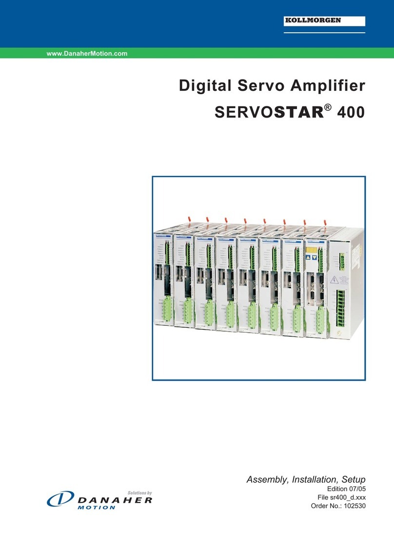
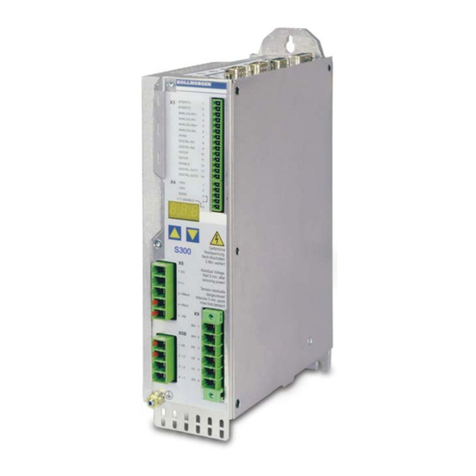
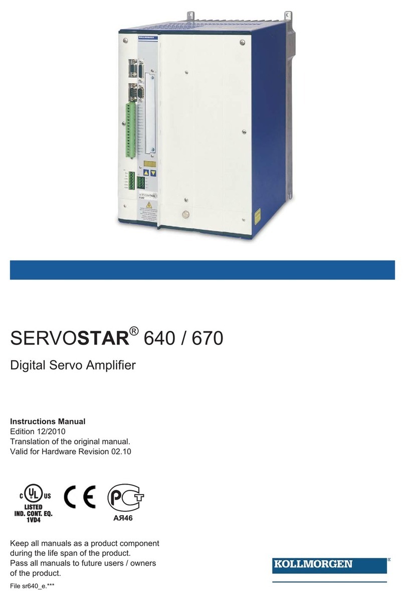
Kollmorgen SERVOSTAR SBD Series User manual

Danaher Motion
SERVOSTAR®SBD Series
Installation Manual
KOLLMORGEN
giving our customers freedom of design
M-ST-009-2031
StockCheck.com

Record of Manual Revisions
ISSUE NO. DATE BRIEF DESCRIPTION OF REVISION
1 08/11/2000 Initial Release
2 11/23/2000 Revised Power Supply Information for PS Series
3 11/05/2001 Revised Hardware Specifications
Copyright Information
Copyright 2000 Kollmorgen - All rights reserved.
Printed in the United States of America.
Kollmorgen GOLDLINE, SILVERLINE, MOTIONEERING, PLATINUM, and SERVOSTAR® are
registered trademarks of Kollmorgen Corporation, a Danaher Motion Company
NOTICE:
Not for use or disclosure outside of Kollmorgen except under written agreement. All rights are reserved.
No part of this book shall be reproduced, stored in retrieval form, or transmitted by any means, electronic,
mechanical, photocopying, recording, or otherwise without the written permission from the publisher.
While every precaution has been taken in the preparation of the book, the publisher assumes no
responsibility for errors or omissions. Neither is any liability assumed for damages resulting from the use
of the information contained herein.
This document is proprietary information of Kollmorgen that is furnished for customer use ONLY. No
other uses are authorized without written permission of Kollmorgen. Information in this document is
subject to change without notice and does not represent a commitment on the part the Kollmorgen
Corporation. Therefore, information contained in this manual may be updated from time-to-time due to
product improvements, etc., and may not conform in every respect to former issues.
StockCheck.com

Table of Contents Danaher Motion
SERVOSTAR®SBD-Series ST/CT Product Family i
Table of Contents
GENERAL INFORMATION....................................................................................................................1
USE AS DIRECTED ......................................................................................................................................1
WARRANTY INFORMATION .......................................................................................................................1
ABBREVIATIONS........................................................................................................................................2
SYSTEM DESCRIPTION .........................................................................................................................3
PRODUCT FEATURES .................................................................................................................................3
Fault and Safety Detection................................................................................................................................................... 3
General ................................................................................................................................................................................ 3
PART NUMBER DESCRIPTION ....................................................................................................................4
CT ELECTRICAL SPECIFICATIONS .............................................................................................................5
CT Regen Information ...........................................................................................................................6
ST ELECTRICAL SPECIFICATIONS..............................................................................................................6
CONTROL SPECIFICATIONS........................................................................................................................7
FEEDBACK DEVICES..................................................................................................................................7
POWER SUPPLIES ...................................................................................................................................9
FEATURES.................................................................................................................................................. 9
PART NUMBER DESCRIPTION ..................................................................................................................10
SIMPLIFIED SCHEMATIC ..........................................................................................................................11
BUS ELECTRICAL SPECIFICATIONS......................................................................................................... 12
BUS MODULE REGEN INFORMATION ......................................................................................................13
Kit Parts and Models...........................................................................................................................13
HARDWARE INSTALLATION.............................................................................................................15
UNPACKING AND INSPECTION ................................................................................................................. 15
MOUNTING ..............................................................................................................................................15
SERVOSTAR CT Hardware Specifications .........................................................................................16
SERVOSTAR ST Hardware Specifications..........................................................................................17
BUS Module Hardware Specifications................................................................................................18
OUTLINE DIMENSIONS.............................................................................................................................19
ST and PS Units...................................................................................................................................19
CT Units...............................................................................................................................................20
PA-LM Units........................................................................................................................................20
INSTALLATION PRACTICES......................................................................................................................21
Enclosure.............................................................................................................................................21
Wiring Practices..................................................................................................................................21
Grounding............................................................................................................................................21
Bonding................................................................................................................................................22
Non-insulated Cable Clamp............................................................................................................................................... 22
Alternative Bonding Methods............................................................................................................................................ 23
SYSTEM INTERCONNECT ..........................................................................................................................24
Views....................................................................................................................................................24
System Phasing Information................................................................................................................18
ST Wiring Diagram with PS 08, 20, or 40...........................................................................................25
ST System Wiring Diagram Notes .................................................................................................................................... 26
CT Wiring Diagram.............................................................................................................................27
CT Wiring Diagram Notes................................................................................................................................................. 28
OPERATION INFORMATION..............................................................................................................29
SYSTEM I/O .............................................................................................................................................29
StockCheck.com

Danaher Motion Table of Contents
ii SERVOSTAR®SBD-Series ST/CT Product Family
Tachometer Input (C2 Pins 1 and 3) ...................................................................................................29
Current Monitor (C2 Pin 5).................................................................................................................29

Tachometer Monitor (C2 pin 6)...........................................................................................................29
CW and CCW Limit Inputs (C2 pins 8 and 9) .....................................................................................29
Remote Enable Input (C2 Pin 10)........................................................................................................30
External Current Limit (C2 pin 11).....................................................................................................30
Torque Hold Input (C2 pin 12)............................................................................................................30
Analog Input (C2 pins 13 and 14).......................................................................................................30
CONTROL LOOPS......................................................................................................................................31
Current Loop .......................................................................................................................................31
Velocity Loop.................................................................................................................................................................... 32
Current Clamps ...................................................................................................................................34
Torque Limit Pot ............................................................................................................................................................... 34
External Current Limit....................................................................................................................................................... 34
Horse Power Contour ........................................................................................................................................................ 35
POTENTIOMETER ADJUSTMENTS.............................................................................................................36
DC Gain – Scale..................................................................................................................................36
AC Gain – Stability..............................................................................................................................37
Balance – DC Offset............................................................................................................................37
Current Limit.......................................................................................................................................37
SYSTEM STARTUP ................................................................................................................................38
INITIAL STARTUP.....................................................................................................................................38
Power-Up Sequence.............................................................................................................................38
Enabling the System.............................................................................................................................38
Drive Tuning........................................................................................................................................38
ADJUSTMENTS .........................................................................................................................................39
SERVOSTAR HELP.................................................................................................................................40
FAULT MONITORING SYSTEM..................................................................................................................40
TROUBLESHOOTING LIST.........................................................................................................................41
SUPPORT...................................................................................ERROR! BOOKMARK NOT DEFINED.
CUSTOMER SUPPORT...............................................................................................................................42
StockCheck.com

General Information Danaher Motion
SERVOSTAR®SBD-Series ST/CT Product Family iii
Safety Instructions
Only qualified personnel are permitted to transport, assemble, install, and maintain this equipment.
Properly qualified personnel are persons who are familiar with the transport, assembly, installation,
commissioning and operation of motors, and who have the appropriate qualifications for their jobs. The
qualified personnel must know and observe the following standards and regulations:
IEC 364 resp. CENELEC HD 384 or DIN VDE 0100
IEC report 664 or DIN VDE 0110
National regulations for safety and accident prevention or VBG 4
Read all available documentation before assembly and installation. Incorrect handling of products in this
manual can result in injury and damage to persons and machinery. Strictly adhere to the technical
information on the installation requirements.
It is vital to ensure that all system components are connected to earth ground. Electrical safety is
impossible without a low-resistance earth connection.
The SERVOSTAR®product contains electrostatically sensitive components that can be damaged by
incorrect handling. Discharge yourself before touching the product. Avoid contact with high insulating
materials (artificial fabrics, plastic film, etc.). Place the product on a conductive surface.
During operation keep all covers and cabinet doors shut. Otherwise, there are deadly hazards that could
possibility cause severe damage to health or the product.
In operation, depending on the degree of enclosure protection, the product can have bare components that
are live or have hot surfaces. Control and power cables can carry a high voltage even when the motor is
not rotating.
Never pull out or plug in the product while the system is live. There is a danger of electric arcing and
danger to persons and contacts.
After powering down the product, wait at least 10 minutes before touching live sections of the equipment
or undoing connections (e.g. contacts, screwed connections). Capacitors can store dangerous voltages for
long periods of time after power has been switched off. To be safe, measure the contact points with a
meter before touching.
The safety-alert symbols contained in this manual are:
"Warning" alerts users to potential danger or harm. Failure to follow warning notices could
result in personal injury or death.
"Caution" directs attention to general precautions, which if not followed, could result in
personal injury and/or equipment damage.
"Note" highlights information critical to the users understanding or use of these products.
When these symbols are seen in this manual, be alert to the potential for personal injury. Follow the
recommended precautions and safe operating practices included with the alert symbols. Safety notices in
this manual provide important information. Read and be familiar with these instructions before attempting
installation, operation, or maintenance. The purpose of this section is to alert users to possible safety
hazards associated with this equipment and the precautions that need to be taken to reduce the risk of
personal injury and damage to the equipment. Failure to observe these precautions could result in serious
bodily injury, damage to the equipment, or operational difficulty.
StockCheck.com

Danaher Motion General Information
iv SERVOSTAR®SBD-Series ST/CT Product Family
Directives and Standards
The SERVOSTAR product series has been successfully tested and evaluated to meet UL/cUL 508C for
U. S. and Canadian markets. This standard outlines the minimum requirements for electrically operated
power conversion equipment (frequency converters and servo amplifiers), which are intended to eliminate
the risk of fire, electric shock, or injury to persons, being caused by such equipment.
Mark Conformance
Servo drives are incorporated in electrical plants and machines for industrial use. When the servo drives
are built into machines or plants, the operation of the drive is prohibited until the machine or plant meets
the requirements of the EC Directive on Machines 89/392/EEC and the EC Directive on EMC
(89/336/EEC). EN 60204 and EN 292 must also be met.
In connection with the Low Voltage Directive 73/23/EEC, the harmonized standards of the EN 50178
series are applied to the amplifiers, together with EN 60439-1, EN 60146 and EN 60204.
The manufacturer of the machine or plant is responsible for ensuring that they meet the limits; which are
required by the EMC regulations. Advice on the correct installation for EMC - such as shielding,
grounding, arrangement of filters, treatment of connectors and the lay out of cabling can be found in this
documentation.
Conformance with the EC Directive on EMC 89/336/EEC and the Low Voltage Directive 73/23/EEC is
mandatory for the supply of servo drives within the European Community.
The servo drives have been tested by an authorized testing laboratory in a defined configuration with the
system components; described in this documentation. Kollmorgen is not responsible for any divergence
from the configuration and installation described in this documentation and is not responsible for the
performance of new measurements or ensuring that regulatory requirements are met.
Kollmorgen’s SERVOSTAR products and systems have been successfully tested and evaluated to the
limits and requirements of the EC Directive on EMC (89/336/EEC) and the EC Directive on Low Voltage
(72/73/EEC). The product lines have been evaluated to EN50178 and EN60204 as a component of a
machine and other relevant standards.
The Electromagnetic Compatibility (EMC) of a system is identified in two parts: emissions and
immunity. Emissions are the generation of EMI (electromagnetic interference) and immunity is the
susceptibility levels of the equipment. Limits are derived from generic standards EN55081-2 and
EN55082-2 for heavy industrial environment. The SERVOSTAR series of drives and BUS modules have
been tested for radiated emissions, conducted emissions, EFT, ESD, surge, conducted immunity, and
radiated immunity. These tests have been in accordance with EN55011, EN61000-4-2, ENV50140, IEC
1000-4-4, EN61000-4-5, and ENV50141.
Installation of the equipment is critical in designing system and machine electro-magnetic
compatibility (EMC). The user must apply the installation recommendations in this manual. See
the installation section and CE Filtering Techniques information when mounting and installing
the drive system for CE conformance.
StockCheck.com

Danaher Motion General Information
SERVOSTAR®SBD-Series ST/CT Product Family 1
General Information
This manual is designed to lead you through the proper installation and setup of a SERVOSTAR®SBD
Series servo system. It was developed with the assumption that there is a fundamental understanding of
basic electronics, mechanics, and proper safety practices. However, you do not have to be an expert in
motion control to install and operate the drive system. It is recommended that you read the entire manual
completely before installation and operation is attempted.
USE AS DIRECTED
The following guidelines describe the restrictions for proper use of the SERVOSTAR SBD system:
• These amplifiers are components, which are built into electrical equipment or machines and can
only be commissioned as integral components of such equipment.
• The servo amplifiers are to be used only on earthed single or three-phase industrial mains supply
networks (TN-system, TT-system with earthed neutral point).
• The servo amplifiers must not be operated on power supply networks without an earth or with an
asymmetrical earth.
• If the servo amplifiers are used in residential areas, or in business or commercial premises, then
the user must implement additional filter measures.
• The servo amplifiers are only intended to drive specific brush-type servomotors from
Kollmorgen, with closed-loop control of torque and velocity. The rated voltage of the motors
must be at least as high as the DC-link voltage of the servo amplifier.
• The servo amplifiers may only be operated in a closed switch gear cabinet, taking into account
the ambient conditions defined in the environmental specifications.
WARRANTY INFORMATION
All products covered in this manual are warranted to be free of defects in material and workmanship and
to conform to the specifications stated either in this document or product catalog description. All
Kollmorgen brushless motors and electronics are warranty for a period of 24 months from the time of
installation or 30 months from time of shipment, which ever comes first. There are no other warranties,
expressed or implied (including the warranty of merchantability and fitness for a particular purpose,
which extends beyond this warranty. Kollmorgen warrants that the products covered in the manual are
free from patent infringement when used for normal purposes.
StockCheck.com

Danaher Motion General Information
2 SERVOSTAR®SBD-Series ST/CT Product Family
ABBREVIATIONS
AC Alternating Current
AppNote Application Note
CCW Counter Clockwise*
CMR Common Mode Rejection
CW Clockwise*
DC Direct Current
Diff Differential
EMF Electro-Motive Force
EMC Electromagnetic Compatibility
EMI Electromagnetic Interference
ESD Electrostatic Discharge
Ext External
Hz Hertz
I Current
Info Information
I/O Input / Output
KHz KiloHertz
KCSN Kollmorgen Customer Support Network
KW KiloWatts
LED Light Emitting Diode
Lim Limit
NEC National Electrical Code
PSP Product Support Package
P/N Part Number
PWM Pulse Width Modulation
Regen Regeneration
RMS Root Mean Square
Tach Tachometer
UL Underwriters Laboratories
* Clockwise and counterclockwise reference as viewing the motor output shaft.
StockCheck.com

Danaher Motion System Description
SERVOSTAR®SBD-Series ST/CT Product Family 3
System Description
The SERVOSTAR SBD-Series is a four-quadrant analog brush-type servo motor drive amplifier that
meets the needs of many servo applications such as machine tooling, packaging, electronic assembly, and
document handling. The SBD-Series of drives comes in standard packages of 3, 6, 10, 20, 30, 55, and 85
amps. A wide range complementary of Power Supply Modules are also available. A CT-series (Compact
Drive), that includes an integrated BUS module, is available in 3, 6 and 10 amp sizes. All are packaged in
a small frame size perfect for minimizing cabinet space. This product is a velocity controller commanded
through an industrial standard +/- 10V analog interface using a DC tachometer generator for velocity
feedback.
PRODUCT FEATURES
The SERVOSTAR SBD is a brush motor drive capable of controlling the motor’s velocity using a
tachometer generator mounted to the motor as the feedback device. The drive is designed as a modern
update to Kollmorgen’s SBD Series of brush drive amplifiers produced over the past 25 years. The drive
is fully analog and can receive the exact comp (compensation) card that was used in existing SBD2
application. The drive is built on Kollmorgen’s SERVOSTAR S-Series platform, which uses modern
technology and has a long life expectancy. The SERVOSTAR S-Series of brush drives is modular in
design meaning that it has a separate power supply module. The PS Series of power supply modules are
fully compatible to the SERVOSTAR SBD Series of products.
Fault and Safety Detection
Over Voltage protection
Over Current Protection (Short Circuit)
Under Voltage Lock-out (Can be disabled)
Motor Over Speed Protection
Over Temperature Protection (Drive’s internal temperature)
General
Industry Standard +/- 10 Volt command signal input
External Regeneration Capability
SBD2 Compensation-Compatible Drive
Wide Range of Power Capacity
Smaller units available with integral Power Supply
Units available with Modular Power Supply
StockCheck.com

Danaher Motion System Description
4 SERVOSTAR®SBD-Series ST/CT Product Family
PART NUMBER DESCRIPTION
Month
Mftd
A - January
B - February
:
:
L - December
S 9 8 A-5 8 9
CT03000-SBD2-4236AA2/160-03
Unit Manufactured
Year Manufactured
Hardware Variations:
000 – Standard Product
Rated Current
(A )
S-Series: 03, 06, 10, 20, 30, 55,
8
C-Series: 03, 06, 10
Feedback
T - Tachometer
Rl
SERVO
STAR®Amplifier Family:
S - S Series
C - C Series (Compact Drive) Intended Bus Voltage
Intended Drive
Rating
Tachometer Voltage:
Facility:
Blank - Radford
C - China
S - Israel
M - Spain
Z - Israel
SBD2 – Compatible Compensation
Motor Frame:
Motor Winding :
StockCheck.com

Danaher Motion System Description
SERVOSTAR®SBD-Series ST/CT Product Family 5
CT ELECTRICAL SPECIFICATIONS
Product Model CT03 CT06 CT10
Main Input Power Voltage (VACL-L) Nominal ±10% 63-230
Phases 1 / 3
Line Frequency 47-63
KVA @ 115 (1φ
φφ
φ)0.44 0.89
0.89
Continuous Current (amps) @ 115VAC 3.9 7.7 7.7
Peak Current (amps) for 500 mSec 115VAC 11.7 23.1 23.1
Peak Current (amps) for 2Sec 115VAC 7.8 15.4 15.4
KVA @ 230(1φ
φφ
φ)0.89 1.8
1.8
Continuous Current (amps) @ 230(1φ) 3.9 7.7
7.7
Peak Current (amps) for 500mSec @ 230(1φ) 11.7 23.1
23.1
Peak Current (amps) for 2Sec @ 230(1φ) 7.8 15.4
15.4
Line Fuses (FRN-R, LPN, or equivalent) 10 20 20
KVA @ 230(3φ
φφ
φ)1.4 2.8 4.6
Continuous Current (amps) @ 230(3φ) 3.5 7 12
Peak Current (amps) for 500mSec @ 230(3φ) 10.5 21 36
Peak Current (amps) for 2Sec @ 230(3φ) 7 14 24
Line Fuses (FRN-R, LPN, or equivalent) 10 20 25
Logic Input Power +24VDC Ext. Logic Voltage (volts) 22 - 27
+24VDC Ext. Logic Current (amps sink) 1.5
SoftStart Max. Surge Current (amps) 30
Max. Charge Time (sec) .25
Protection Functions Fault Contact Rating 1A
Fault Contact Closing Period (mSec) Close = 3mS, Open = 2mS
OverTemperature trip (°C) 80°C
Rated Main Output
(Ma, Mb, Mc) Continuous Power (KVA) @ 115VAC 1φLine
Input (45°Ambient) 0.35 0.7 0.7
Continuous Power (KVA) @ 230VAC 1φLine
Input (45°C Ambient) 0.7 1.4
1.4
Continuous Power (KVA) @ 230VAC 3φLine
Input(45°Ambient) 1.1 2.2 3.5
Continuous Current (Adc) 3 6 10
Peak Current (Adc) for 500mSec 9 18 20
Peak Current (Adc) for 2Sec 6 12 20
PWM Frequency (kHz) 10 10 10
PWM Motor Current Ripple (kHz) 20 20 20
Protective Functions UnderVoltage Trip (nominal) 90 VDC (Can be defeated)
OverVoltage Trip 430 VDC
OverTemperature Trip 80°C
Internal heat dissipation (watts – maximum)) 60 80 132
Environment Operation temperature (°C) 5 to 45°C
Storage temperature (°C) -0 to 70
Ambient humidity 10% to 90%
Atmosphere w/o no corrosive gasses or dust
Altitude Derate 5% per 1000ft (300m) above 3300ft (1000m)
Vibration 0.5 g
StockCheck.com

Danaher Motion System Description
6 SERVOSTAR®SBD-Series ST/CT Product Family
CT Regen Information
Product Model CT03 CT06 CT10
Internal Shunt Regulator Peak current (amps) N / A
Resistance (ohms)
Watts
Fuse Rating (amps)(internal)
External Shunt Regulator Peak current (amps) 20
Minimum resistance (ohms) 20
Watts 200
Application Information Capacitance (Farads) .00082 .00164
BUS Voltage (nominal) (VDC) 325
VHYS (Regen circuit turn-off) (VDC) 370
VMAX (Regen circuit turn-on) (VDC) 390
Internal Regen Resistance (Ω) N / A
Power Rating (Watts)
External Regen Kits ERH-26 aaa
*For guidance on application sizing of Regen Kits, see Application Note, SERVOSTAR S/C-Series
Regeneration Requirements on the PSP CD-ROM, or the Kollmorgen website (www.MotionVillage.com).
ST ELECTRICAL SPECIFICATIONS
Product Model ST03 ST06 ST10 ST20 ST30 ST55 ST85
BUS (VDC) to 360 to 360
Main Input Rated Power @ DC (kW) 0.63-1.4 1.26-2.79 1.96-4.34 8.68 13.33 24.45 37.20
Continuous Power (KVA) @ 115VAC 1φ
Line Input (45°Ambient) 0.55 1.1 1.6 n/a n/a n/a n/a
Continuous Power (KVA) @ 230VAC 1φ
Line Input (45°C Ambient) 1.1 2.2 3.2 3.2 n/a n/a n/a
Continuous Power (KVA) @ 230VAC 3φ
Line Input(45°Ambient) 1.1 2.2 3.6 7.3 11 20 30
Continuous Current (Adc) 3 6 10 20 30 55 85
Peak Current (Adc) for 500mSec 6 12 20 40 60 110 170
Peak Current (Adc) for 2Sec 6 12 20 40 60 110 170
PWM Frequency (kHz) 10 10
Rated Main Output
(MA, MB, MC)
PWM Motor Current Ripple (kHz) 20 20
+8VDC Supply Voltage 7.3-8.5
+8VDC Supply Current (amps) 0.5
±15VDC Supply Voltage 14.3-15.5
Control Input ±15VDC Supply Current (amps) .37 .38 .5 .47 .66 .87
UnderVoltage Trip (on power-up)
(Can be defeated) 90 VDC 255 VDC
UnderVoltage Trip (nominal)
(Can be defeated) 90 VDC 125 VDC
OverVoltage Trip 430 VDC
Protective
Functions
OverTemperature Trip 118°C 90°C
Internal heat dissipation in 45°ambient @
continuous current (Maximum Watts) 37 w 84 w 120 w 240 w 254 w 465 w 675 w
Operation temperature (°C) 0 to 45°
Storage temperature (°C) -20 to 70°
Humidity (non-condensing) 10% to 90%
Atmosphere w/o corrosive gasses or dust
Altitude Derate 5% per 1000ft above 3300ft
Environment
Vibration 0.5 g
StockCheck.com

Danaher Motion System Description
SERVOSTAR®SBD-Series ST/CT Product Family 7
CONTROL SPECIFICATIONS
I/O Connector (C3 by pinout)
Analog Input (2,3) Maximum Voltage 13 V differential
Fault Output Relay (5,6) Max Capacity 500mA @ 110VAC
User Controls (Enable,
CW/CCW Lim, Torque Hold,
Ext I Limit
Operation Tie to common to activate circuit.
DO NOT APPLY VOLTAGE.
FEEDBACK DEVICES
The SERVOSTAR SBD is designed for use with analog tachometer feedback only. The absolute
maximum voltage that the tachometer is allowed to generate and send to the control electronics is 100V.
StockCheck.com

Danaher Motion System Description
8 SERVOSTAR®SBD-Series ST/CT Product Family
StockCheck.com

Danaher Motion Power Supplies
SERVOSTAR®SBD-Series ST/CT Product Family 9
Power Supplies
The SERVOSTAR family includes a variety of BUS modules that convert a single-phase logic voltage
and a single or three-phase AC line into the drive’s DC logic power and main DC BUS.
Brush motor design makes them more sensitive to high voltage conditions than brushless motors. The PS
power supply family offers a number of voltage ratings designed to shunt-regulate regenerated power to
maintain safe operating voltage levels. Operating these power supplies with higher-than-designed input
voltages can cause regen circuit failure.
FEATURES
• Converts single or three-phase AC main lines (or transformer outputs) into a rectified DC BUS
(check BUS module Electrical Specifications table to verify specific BUS module operation). The
input consists of a 3φdiode bridge, soft-start circuitry, and BUS capacitors. These capacitors help
to minimize BUS ripple, and therefore BUS drooping, during the peak power demands of the
load.
• All units have soft-start capability to gradually develop the DC BUS allowing direct line
connection to minimizes the effect of “in-rush” current spikes inherent in a power-up cycle.
• An external Shunt Regulator option to dissipate regenerative energy while maintaining a safe
operating voltage for the motor.
• The logic BUS module on all units consists of a switching power supply to develop the required
±15V and +8V from either the main line (use LAand LB) or a separate AC logic input.
• Product features are:
Indicator PS10 PS20/40 PS50/75/85
1Green LED X X X
2Yellow LED n/a X X
3Red LED n/a n/a X
4Fault Relay n/a X X
5SoftStart X X X
6Regeneration n/a I/E E
1Indicates when voltage is on the caps.
2Indicates unit is operating in regen and may flash during aggressive accelerations.
3Indicates unit is still in SoftStart. This LED is also used to indicate when an
OverVoltage fault has occurred from too much power being pumped back into the
system during regen.
4The relay is a normally-open contact and closes after the unit is powered-up and out of
SoftStart. The contact will open if there is an improper BUS module voltage (dropping in
and out of SoftStart), an over-heated internal regen resistor, or the main heatsink
becomes too hot.
5Contains SoftStart capability
6E-external, I-internal
StockCheck.com

Danaher Motion Power Supplies
10 SERVOSTAR®SBD-Series ST/CT Product Family
• The PA-LM unit is a logic supply only and should be used in multi-axis applications where the
bus power supply already exists. This unit comes with three green LEDs that verify the presence
of the +15V, -15V, and 8V sources.
See BUS Electrical Specifications on page Error! Bookmark not defined. far
details on the features.
PART NUMBER DESCRIPTION
M
ont
h
M
anu
f
acture
d
A - January
B - February
:
:
L - December
9 8 A-5 8 9
P S 20 160
Unit Manufactured
Year Manufactured
Rated Current (Amps):
10,20,40, 60, 85, 100, LM
Output Voltage
90 – 90 Vdc
120 – 120 Vdc
160 – 160 Vdc
225 – 225 Vdc
325 – 325 Vdc
SERVOSTAR®BUS Module
StockCheck.com

Danaher Motion Power Supplies
SERVOSTAR®SBD-Series ST/CT Product Family 11
SIMPLIFIED SCHEMATIC
RED
YELLOW LED
REGEN FAULT
LED
REGEN
(NORMALLY CLOSED)
FAULT: TO DRIVE
3
POWER
INPUT
BUS-
C
R
BUS+
-
+
Regen
Circuit
I2T
Fault
JUMPER R-C FOR
INTERNAL REGEN
(PA 14/28 ONLY)
EXTERNALLY
ISOLATION
OPTICAL
SoftStart
Control POWER
BUSDC
UnderVolt
Monitor
OverVoltage
Monitor
OverCurrent
Monitor
OPTIONAL EXTERNAL
REGEN RESISTOR
StockCheck.com

Danaher Motion Power Supplies
12 SERVOSTAR®SBD-Series ST/CT Product Family
BUS ELECTRICAL SPECIFICATIONS
PSx0090 PSx0120 PSx0160 Px20225 Px20325
Voltage (VACL-L) Nominal
±10% 64
(1φ/3φ) 85
(1φ/3φ) 115
(1φ/3φ) 160
(1φ/3φ) 230
(1φ/3φ)
Line Frequency 47/63 47/63 47/63 47/63 47/63
PS20 Rated Continuous
Input Current (Amps/Phase) 14 14 14 14 14
PS40 Rated Continuous
Input Current (Amps/Phase) 28 28 28 28 28
Peak Current (amps) for
2sec / 50msec 28/42 28/42 28/42 28/42 28/42
Main Input
Power
Line Fuses (FRN, LPN, or
eqv) PS20/PS40 20 / 40 20/40 20/40 20/40 20/40
DC BUS Voltage (Nominal)
(VDC) 90 120 160 225 365
PS20 Bus Current
(Amps DC) (1φ/3φ) 20 20 20 20 20
PS40 Bus Current (Amps
DC) (3φOnly) 40 40 40 40 40
Main Output
Power
Max. # of Drives Sourced 2 2 2 2 2
Voltage
(VAC nominal +/- 10%) 115 (1φ) 115 (1φ) 115 (1φ) 115 (1φ) 115 (1φ)
Logic Input
Power Current
(Amps AC) 1 1 1 1 1
+8 V Supply
(Volt Range/Amps) 7.25-8.5 /
2.2 7.25-8.5 /
2.2 7.25-8.5 /
2.2 7.25-8.5 /
2.2 7.25-8.5 /
2.2
Analog Supplies
(Volt Range / Amps) +/- 14.25-
16 / 0.8 +/- 14.25-
16 / 0.8 +/- 14.25-
16 / 0.8 +/- 14.25-
16 / 0.8 +/- 14.25-
16 / 0.8
Logic Power
Output Internal Fusing
(8V/15V Amps) 1.5 / 3.5 1.5 / 3.5 1.5 / 3.5 1.5 / 3.5 1.5 / 3.5
Turn-Off Level
(on power-up)
VDC Bus
50 50 90 120 180
Turn-On Level (normal) 30 30 70 100 160
Soft Start
Max. Charge Time (sec) 0.75 0.75 0.75 0.75 0.75
Fault Contact Rating 1 Amp
115VAC 1 Amp
115VAC 1 Amp
115VAC 1 Amp
115VAC 1 Amp
115VAC
Fault Contact Closing
Period (mSec) 250 250 250 250 250
Protection
Over Temperature trip (°C) 90 90 90 90 90
Internal heat dissipation
(watts) (20/40) 70/125 70/125 70/125 70/125 70/125
Operation temperature (°C) 5 to 45 5 to 45 5 to 45 5 to 45 5 to 45
Storage temperature (°C) 0-70 0-70 0-70 0-70 0-70
Altitude (Ft)
Derate 5% per 1000 over
3300
3300 3300 3300 3300 3300
Vibration (g) 0.5 0.5 0.5 0.5 0.5
Environmental
Ambient humidity 10-90 10-90 10-90 10-90 10-90
StockCheck.com

Danaher Motion Power Supplies
SERVOSTAR®SBD-Series ST/CT Product Family 13
BUS MODULE REGEN INFORMATION
Product Model PS20 PS40
Peak current (amps) 30 32
Resistance (ohms) 7.5 12.5
Watts 40 40
Internal Shunt
Fuse Rating (amps)(internal) 7 8
Peak current (amps) 40 45
Minimum resistance (ohms) V Regen/40 V Regen / 45
External Shunt
Watts (max) 300 400
Application Info Capacitance (Farads) .00165 .00198
Resistance (Ω) 12.5
Internal Regen Power Rating (Watts) 40
*For guidance on application sizing of Regen Kits, see Application Note, SERVOSTAR S/C-Series
Regeneration Requirements on the PSP CD-ROM, or the Kollmorgen website (www.MotionVillage.com).
Kit Parts and Models
Kit Parts / Kit Models ERH-26 ERH-40
Resistance (Ω) 20 8.8
Power Rating (Watts) 200 100
Resistor
Kollmorgen Part No. P-97742-001
Relay Trip Setting (amps) n/a n/a
Kollmorgen Part No. n/a n/a
Overload Relay (Fast Trip)
Auto/Manual Setting n/a n/a
Thermostat Thermal Rating (°C) Internal to Box Internal to Box
Hookup Wire Gauge / Temp. Rating #8awg / 125°C
StockCheck.com

Danaher Motion Power Supplies
14 SERVOSTAR®SBD-Series ST/CT Product Family
StockCheck.com
This manual suits for next models
1
Table of contents
Other Kollmorgen Amplifier manuals

Kollmorgen
Kollmorgen S70601-SE User manual

Kollmorgen
Kollmorgen SERVOSTAR 300 User manual

Kollmorgen
Kollmorgen S700 Series User manual

Kollmorgen
Kollmorgen SERVOSTAR 300 User manual

Kollmorgen
Kollmorgen S772 User manual

Kollmorgen
Kollmorgen SERVOSTAR 614 User manual

Kollmorgen
Kollmorgen S700 Series User manual

Kollmorgen
Kollmorgen SERVOSTAR S300 Parts list manual

Kollmorgen
Kollmorgen SERVOSTAR 601 User manual

Kollmorgen
Kollmorgen SERVOSTAR 640 User manual