Komfovent MOU-24HN1-Q User manual
Installation manual
AIR CONDITIONER
OUTDOOR UNITS

2
Content
Safety considerations .......................... 3
Installation information .......................... 3
Installation place .......................... 4
Outdoor unit installation .......................... 5
Install the connecting pipe .......................... 6
Wiring ......................... 11
Piping diagrams ......................... 13
Outdoor unit connection to KOMPAKT and VERSO units ........................ 14
Test operation ......................... 17
Self - diagnosis and troubleshooting ......................... 17
Indoor Temp. and Pipe Temp. Sensor Resistance Value ......................... 20
Outdoor Units
3
Safety considerations
Installation and servicing of air conditioning equipment can be hazardous due to system pressure
andelectric components. Only trained and qualied service personnel should install, repair or service air
conditioning equipment.
Before performing service or maintenance operations on system, turn off main
power switch of the unit. Electrical shock could cause personal injury.
This unit shall be installed in accordance with national wiring regulations.
If the supply cord is damaged, it must be replaced by the manufacturer or
its service agent or similarly qualied person in order to avoid a hazard.
The means for disconnection from the supply having a contact separation
of at least 3 mm in all poles.
Caution
1. Wire the outdoor unit, then wire the indoor unit. You are not allow to connect the air conditioner
with the power source until wiring and piping the air conditioner is done.
2. For installation of the indoor unit, outdoor unit, and connection piping in between, follow the
instructions given in this manual as strictly as possible.
3. Installation in the following places may cause trouble. If it is unavoidable using in such places,
please consult with the dealer.
a) A place full of machine oil.
b) A saline place such as coast.
c) Hot-spring resort.
d) A place full of sulde gas.
e) A place where there are high frequency machines such as wireless installation, welding
machine, medical facilities.
f) A place of special environmental conditions.
4. Don’t install this unit in the laundry.
üNote
Remark per EMC Directive 89/336/EEC or to prevent icker impressions during the start of the
compressor (technical process) ,following installation conditions do apply.
1. The power connection for the air conditioner has to be done at the main power distribution. The distribution
has to be of a low impedance, normally the required impedance reaches at a 32 A fusing point.
2. No other equipment has to be connected with this power line.
3. For detailed installation acceptance please refer to your contract with the power supplier, if restrictions do
apply for products like washing machines, air conditioners or electrical ovens.
4. For power details of the air conditioner refer to the rating plate of the product.
5. For any question contact your local dealer.
Installation information
• To install properly, please read this “installation manual” at rst.
• The air conditioner must be installed by qualied persons.
• When installing the indoor unit or its tubing, please follow this manual as strictly as possible.
• When all the installation work is nished, please turn on the power only after a thorough check.
• Regret for no further announcement if there is any change of this manual caused by product improvement.
Outdoor Units

4
Installation order
1. Select the location;
2. Install the indoor unit;
3. Install the outdoor unit;
4. Install the connecting pipe;
5. Connect the drain pipe;
6. Wiring;
7. Test operation.
Outdoor Units
Installation place
Cautions
Location in the following places may cause malfunction of the machine.(If unavoidable, please
consult your local dealer)
a. There is petrolatum existing.
b. There is salty air surrounding (near the coast).
c. There is caustic gas (the sulde, for example) existing in the air (near a hot spring).
d. The Volt vibrates violently (in the factories).
e. In buses or cabinets.
f. In kitchen where it is full of oil gas.
g. There is strong electromagnetic wave existing.
h. There are inammable materials or gas.
i. There is acid or alkaline liquid evaporating.
j. Other special conditions.
Notices before installation
1. Select the correct carry-in path.
2. Move this unit as originally packaged as possible.
3. If the air conditioner is installed on a metal part of the building, it must be electrically insulated according
to the relevant standards to electrical appliances.
1. The outdoor unit
• There is enough room for installation and maintenance.
• The air outlet and the air inlet are not impeded, and can not be reached by strong wind.
• It must be a dry and well ventilating place.
• The support is at and horizontal and can stand the weight of the outdoor unit. And will no additional
noise or vibration.
• Your neighborhood will not feel uncomfortable with the noise or expelled air. There is no leakage of
combustible air.
• It is easy to install the connecting pipe or cables.
• Determine the air outlet direction where the discharged air is not blocked.
• A place free of a leakage of combustible gases. In the case that the installation place is exposed to
a strong wind such as a seaside or high position, secure the normal fan operation by putting the unit
lengthwise along the wall or using a duct or shield plates.
• If possible, do not install the unit where it is exposed to direct sunlight.
• If necessary, install a blind that does not interfere with the air ow.
• During the heating mode, the water drained off the outdoor unit ,The condensate should be well
drained away by the drain hole to an appropriate place, so as not to interfere other people or public.
• Select the position where it will not be subject to snow drifts, accumulation of leaves or other seasonal
debris. It is important that the air ow for the outdoor unit is not impeded as this will result in reduction
in heating or cooling performance.
5
Outdoor Units
Outdoor unit installation
Cautions
• Keep this unit away from direct radiation of the sun or other heaters.
• If unavoidable, please cover it with a shelter.
• In places near coast or with a high attitude where the wind is violent, please install the out-
door unit against the wall to ensure normal performance.
Use a bafe when necessary.
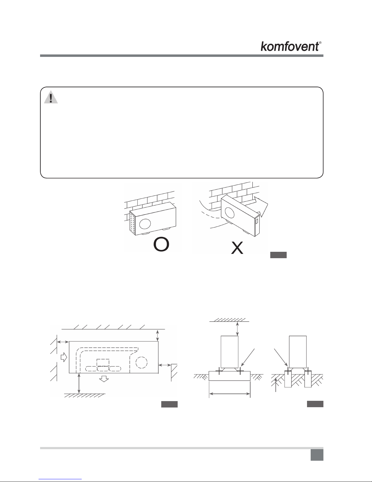
• In the case of extremely strong wind, please prevent the air from owing backwards into the
outdoor unit. ( Refer to chart 16)
• Locate the outdoor unit as close to the indoor unit as possible.
• The minimum distance between the outdoor unit and obstacles described in the installation
chart does not mean that the same is applicable to the situation of an airtight. Leave open
two of three directions A,B,C.
Necessary room for installation and maintenance
(Refer to chart 2, chart 3)
If possible, please remove the obstacles nearby to prevent the performance from being impeded by too little
of air circulation.
The minimum distance between the outdoor unit and obstacles described in the installation chart does not
mean that the same is applicable to the situation of an airtight room. Leave open two of the three directions
(A,B,C).
Chart 1
Strong wind
Wall or obstacle
Air inlet
Air inlet
>30 cm
>60 cm
C
Air outlet
>200 cm
A
>30 cm
Chart 2
Maintain channel
Chart 3
>60 cm
Necessary width
Fix with bolt
Deep foundation

6
Outdoor Units
600mm is necessary between 2 indoor units.
Chart 4
Moving and intalling
• Since the gravity center of this unit is not at its physical center, so please be careful when lifting it with a
sling.
• Never hold the air-in of the outdoor unit to prevent it from deforming.
Do not touch the fan with hands or other objects.
• Do not lean it more than 450, and do not lay it sidelong.
• Please fasten the feet of this unit with bolts rmly to prevent it from collapsing in case of earthquake
• or strong wind.
• Make concrete foundation of the size of 590*328.(Refer to chart 3)
Install the connecting pipe
Cautions
Check whether the height drop between the indoor unit and outdoor unit, the length of
refrigerant pipe, and the number of the bends meet the following requirements:
The max height drop 8, 15, 20, 25 m
If the height drop is more than 10m, you had better put the outdoor unit over above the
indoor unit.
The length of refrigerant pipe 15, 25, 30, 50 m
The number of bends less than15
* Look at specication (page 12.).
Cautions
• Do not let air, dust, or other impurities fall in the pipe system during the time of installation.
• The connecting pipe should not be installed until the indoor and outdoor units have been xed
already.
• Keep the connecting pipe dry, and do not let moisture in during installation.
Refrigerant pipe installation
Measure the necessary length of the connecting pipe, and make it by the following way.
1) Connect the indoor unit at rst, then the outdoor unit.
• Bend the tubing in proper way. Do not harm to them.

7
Chart 5
Use frozen oil
Chart 6
Bend the pipe with thumb
Min-radius - 100 mm
Chart 7
Make the
end straight
Cautions
• Daub the surfaces of the are pipe and the joint nuts with frozen oil, and wrench it for 3~4
rounds with hands before fasten the are nuts.(Refer to chart 5)
• Be sure to use two wrenches simultaneously when you connect or disconnect the pipes.
2) The stop value of the outdoor unit should be closed absolutely (as original state). Every time you connect
it, rst loosen the nuts at the part of stop value , then connect the are pipe immediately (in 5 minutes).
If the nuts have been loosened for a long time, dusts and other impurities may enter the pipe system
and may cause malfunction later. So please expel the air out of the pipe with refrigerant (R410a) before
connection.
3) Expel the air (refer to the “Expel The Air”) after connecting the refrigerant pipe with the indoor unit. Then
fasten the nuts at the repair-points.
üNotices For Bendable Pipe
• The bending angle should not exceed 900.
• Bending position is preferably in the middle of the bendable pipe. The larger the bending radius the better
it is.
• Do not bend the pipe more than three times.
Bend the connecting pipe of small wall thickness (9,5 mm)
• Cut out a desired concave at the bending part of the insulating pipe.
• Then expose the pipe (cover it with tapes after bending).
• To prevent collapsing or deforming, please bend the pipe at its biggest radius.
• Use bender to get a small radius pipes.
Use the market brass pipe
• Be sure to use the same insulating materials when you buy the brass pipe (more than 9mm thick).
Locate The Pipe
• Drill a hole in the wall (suitable just for the size of the wall conduit), then set on the ttings such as the wall conduit
and its cover.
• Bind the connecting pipe and the cables together tightly with binding tapes. Do not let air in, which will
cause water leakage by condensation.
• Pass the bound connecting pipe through the wall conduit from outside. Be careful of the pipe allocation to
do no damage to the tubing.
1. Connect the pipes.
2. So please expel the air out of the pipe with refrigerant (R410a) before connection.
3. Then, open the stem of stop values of the outdoor unit to make the refrigerant pipe connecting the indoor
unit with the outdoor unit in uent ow.
4. Be sure of no leakage by checking it with leak detector or soap water.
5. Cover the joint of the connecting pipe to the indoor unit with the soundproof / insulating heath (ttings), and
bind it well with the tapes to prevent leakage.
Outdoor Units

8
Outdoor Units
Fasten the nuts
• Put the connecting tubing at the proper position, wrench the nuts with hands, then fasten it with a wrench.
( Refer to Chart 10)
1. Cut a pipe with a pipe cutter.
2. Insert a are nut into a pipe and are the pipe.
Outside-diameter
(mm)
A (mm)
Min Max
6.4 8.3 8.7
9.5 12.0 12.4
12.7 15.4 15.8
15.9 18.6 19.1
19.1 22.9 23.3
Cautions
Too large torque will harm the bellmouthing and too small will cause leakage. Please
determine the torque according to Table.
Tubing Size Torque
6.4 15~16 Nm (153~163 kgf-cm)
9.5 25~26 Nm (255~265 kgf-cm)
12.7 35~36 Nm (357~367 kgf-cm)
15.9 45~47 Nm (459~480 kgf-cm)
19.1 65~67 Nm (663~684 kgf-cm)
450 + 20
900 + 40
900lean crude burr
Chart 8
Chart 10
Chart 9
A
450 + 20
900 + 40

9
Necessary Refrigerant Stow Capacity
Length (L) Capacity 18000-24000Btu/h 30000-48000Btu/h
Less than 8m (one-way) —— ——
Added Refrigerant When Over 8m(one-way) 65 x (L-8) m
• Please record and reserve well the refrigerant stow capacity of your air conditioner for later maintenance.
Expel the air with a vacuum pump
(please refer to its manual for the way of using manifold value)
Vacuum Dry: use vacuum pump to change the moisture (liquid) into steam (gas) in the pipe and discharge it out
of the pipe to make the pipe dry. Under one atmospheric pressure, the boiling point of water(steam temperature)
is 1000C. Use vacuum pump to make the pressure in the pipe near vacuum state, the boiling point of water falls
relatively. When it falls under outdoor temperature, the moisture in the pipe will be vaporized.
1. Loosen and remove the maintenance nuts of stop values A and B, and connect the charge hose of the
manifold value with the maintenance terminator of stop value A. (Be sure that stop values A and B are both
closed).
2. Connect the joint of the charge hose with the vacuum pump.
3. Open the Lo-lever (Lo) of the manifold value completely.
4. Turn on the vacuum pump. At the beginning of pumping, loosen the maintenance terminator nut of stop
value B a little to check whether the air comes in (the sound of the pump changes, and the indicator of
compound meter turns below zero). Then fasten the nut.
5. When the pumping has nished, close the Lo-lever of the manifold value completely and turn off the
vacuum pump.
• When you have pumped for over 15 minutes, please conrm that the indicator of multi-meter is on
1.0x10⁻⁵ Pa (-76cmHg).
6. Loosen and remove the quadrangle cover of stop values A and B to open stop value A and B completely,
then fasten them.
7. Disassemble the charge hose from the repair-mouth of stop value A, and fasten the nut.
If the pump can’t achieve below -755mmHg after pumping 2 hours, moisture or leakage point will still exist in
the pipe. At this time, it should be pumped 1 hour more.
Outdoor Units
Chart 11
Manifold valve
Multi-meter Pressure meter
-76 cmHg
Lo - lever Hi- lever
Charge hose
Charge hose
Vacuum pump
Lo- lever
Flare nut
Cap
Stopper
Valve body
Valve stern
Chart 12
10
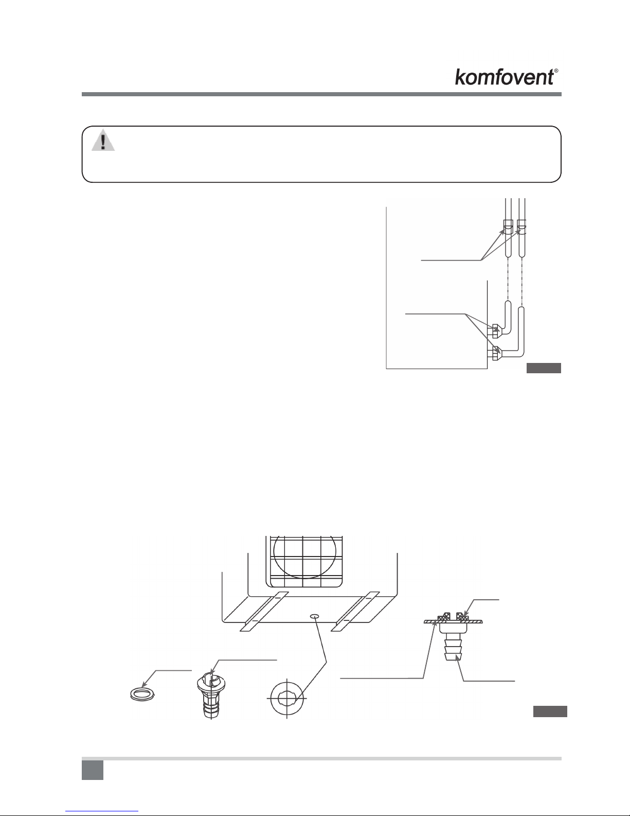
Cautions
All the stop values should be opened before test operation. Each air conditioner has two stop
values of different sizes on the side of the outdoor unit which operate as Lo-stop value and
Hi-stop value, respectively. (Refer to Chart 12)
Check the leakage CHECK THE LEAKAGE
Check all the joints with the leak detector or soap water.
(refer to Chart 13)
NOTE: in the chart 13:
A.......... Lostop value
B .......... Histop value
C, D ..... Joints of the connecting pipe to the indoor unit.
In order to ensure a perfect unit work on the back of low-pressure pipe should be tted with water lter!
Insulation
• Be sure to with insulating materials cover all the exposed parts of the are pipe joints and refrigerant pipe
on the liquid-side and the gas-side. Ensure that there is no gap between them.
• Incomplete insulation may cause water condensation.
Drain Elbow Installation
Fit the seal into the drain elbow, then insert the drain elbow into the base pan hole of outdoor, rotate 900to
securely assemble them. Connect the drain elbow with an extension drain hose (Locally purchased), in case of
the condensate draining off the outdoor unit during the heating mode.
Chart 13
Check-point of
outdoor unit
Check-point of
indoor unit
Outdoor Units
A
B
C
D
Seal
Drain elbow The base pan hole of
outdoor unit Drain elbow
Seal
Chart 14

11
Wiring
Caution!
1. The air conditioner should use separate power supply with rated voltage.
2. The external power supply to the air conditioner should have ground wiring, which is linked to
the ground wiring of the indoor and outdoor unit.
3. The wiring work should be done by qualied persons according to circuit drawing.
4. A disconnection device having an air gap contact separation in all active conductors should
incorporated in the xed wiring according to the National wiring regulation.
5. Be sure to locate the power wiring and the signal wring well to avoid cross-disturbance and
their contact with connecting pipe or stop value body.
6. The wiring attached to this air conditioner is 6m long. Be sure to prolong it with wiring of the
same type and proper length if necessary. Generally, do not twist two wiring together unless
the joint is soldered well and covered with insulator tape.
7. Do not turn on the power until you have checked carefully after wiring.
1. Nominal cooling capacities are based on the following conditions:
Indoor temp: 27°C, relative humidity 50%. Outdoor temp: 35°C; Equivalent ref. Piping: 8m(horizontal)
2. Nominal heating capacities are based on the following conditions:
Indoor temp: 20°C; Outdoor temp: 7°C, relative humidity 90%; Equivalent ref. Piping: 8m(horizontal)
3. Actual noise level may differ, depending on the room structure, etc, since these noise values are from an
anechoic room.
Remove the protection board
Disassemble the bolts from the maintenance board, and pull it in the direction of the arrow to remove
the protection board.
Notice: Do not scratch the surface during operation.
ATTENTION: Chart 15 is based on the standard model, which may look a little different from your
own outdoor unit.
Outdoor Units
Terminator
Protection board
Chart 15
12
Model MOU-12HN1 MOU-18HN1-Q MOU-24HN1-Q MOU-36HN1-R MOU-48HN1-R MOUA-60HN1-R
Power supply V-ph-Hz 230-1-50 230-1-50 230-1-50 400-3-50 400-3-50 400-3-50
Max. input consumption W 1500 2950 3450 4950 6300 7500
Max. input current A 7 15 18 10,0 10,5 12,8
Cooling / Heating capacity W 3520/3810 5280/5860 7030/7620 10550/11720 14100/15240 17600/19100
Compressor
Type ROTARY ROTARY ROTARY Scroll SCROLL SCROLL
Brand MIDEA-TOSHIBA MIDEA-TOSHIBA MIDEA-TOSHIBA SANYO SANYO SANYO
Capacity Btu/h 11567 18697 24498 33438 48109 55956,8
Oil ml ESTEL OIL
VG74, 480
ESTER OIL
VG74, 750
ESTER OIL
VG74/950 FV68S/1700 FV68S 1700 FV68S, 1700
Outdoor unit
Outdoor air ow m3/h 2100 2439 3200 5000 6800 6850
Outdoor noise level
(sound pressure) dB(A) 43 54 55 57 59 59,3
Dimension(W×H×D) mm 780×547×250 762×593×282 845×695×335 990×966×354 900×1167×340 900×1167×340
Packing (W×H×D) mm 910×575×335 887x645x355 965×755×395 1120×1100×435 1032×1307×443 1032×1307×443
Net/Gross weight kg 34/37 39/42 53/57 92/96 110/115 93/99
Refrigerant type R410A R410A R410A R410A R410A R410A
Refrigerant charged
volume g 1120 1400 1900 2900 3250 3200
Design pressure MPa 4.2/1.5 4.2/1.5 4.2/1.5 4.2/1.5 4.2/1.5 4.2/1.5
Refrigerant piping
Liquid side/ Gas side mm φ6.4/φ12.7 φ6.4/φ12.7 φ9.5/φ15.9 φ12.7/φ19 φ12.7/φ19 φ12.7/φ19
Liquid side - Gas side inch 1/4 - 1/2 1/4 - 1/2 3/8 - 5/8 1/2 - 3/4 1/2 - 3/4 1/2 - 3/4
Max. pipe length m 15 25 25 30 50 30
Max. difference in level m 8 15 15 20 25 20
Ambient temp. C cooling: 18~43;
heating: -7~24
Outdoor Units
1. Specication

13
Indoor unit Outdoor unit
Liquid side
3-way valve
Gas side
3-way valve
Heat exchange
(evaporator)
Check valve
(Heating Model only)
Capillary tube
Heat exchange
(Condenser)
Reversing valve
(Heating Model Only)
Cooling
Heating
Accumulator
Compressor
Chart 16
1. For MOU-18HN1 and MOU-24N1, accumulator is not included.
2. Check valve and auxiliary capillary is only for MOU-18HN1.
Outdoor Units
Piping Diagrams
14
Outdoor Units
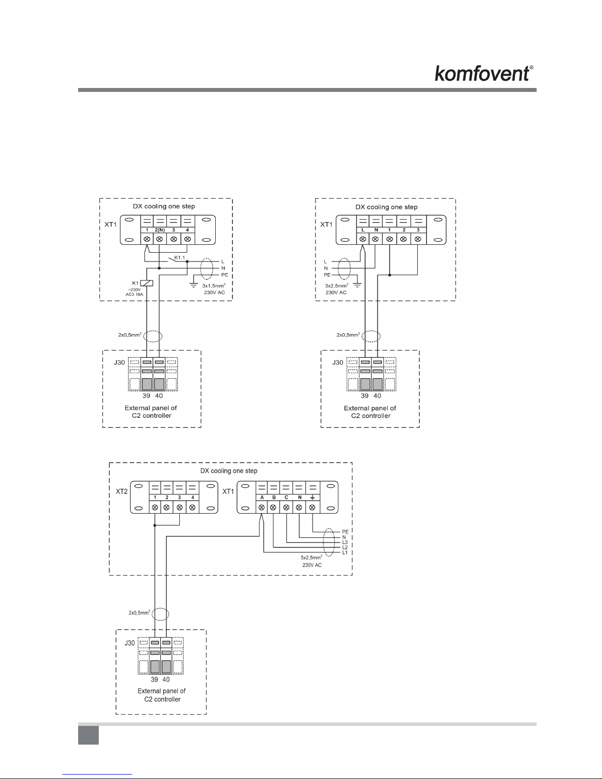
Outdoor unit connection to KOMPAKT and VERSO units
Outdoor unit connection to AHU with C2 controller.
MOU-12HN1 and MOU-18HN1-Q (1 phase) MOU-24HN1(1 phase)
MOU-36HN1, MOU-48HN1 and MOU-60HN1 (3 phases)

15
Outdoor Units
Outdoor unit connection to AHU with C3 controller with external panel C3-P1.
MOU-12HN1 and MOU-18HN1-Q (1 phase) MOU-24HN1(1 phase)
MOU-36HN1, MOU-48HN1 and MOU-60HN1 (3 phases)

16
Outdoor Units
Outdoor unit connection to AHU with C3 controller with external panel P3.
MOU-12HN1 and MOU-18HN1-Q (1 phase) MOU-24HN1(1 phase)
MOU-36HN1, MOU-48HN1 and MOU-60HN1 (3 phases)
17
Outdoor Units
Test operation
1. The test operation must be carried out after the entire installation has been completed.
2. Please conrm the following points before the test operation:
• The indoor unit and outdoor unit are installed properly.
• Tubing and wiring are correctly completed.
• The refrigerant pipe system is leakage-checked.
• The drainage is unimpeded.
• The heating insulation works well.
• The ground wiring is connected correctly.
• The length of the tubing and the added stow capacity of the refrigerant have been recorded.
• The power voltage ts the rated voltage of the air conditioner.
• There is no obstacle at the outlet and inlet of the outdoor and indoor units.
• The gas-side and liquid-side stop values are both opened.
• The air conditioner is pre-heated by turning on the power.
1) The outdoor unit
a. Whether there is vibration or abnormal noise during operation.
b. Whether the generated wind, noise, or condensed of by the air conditioner have inuenced your
neighborhood.
c. Whether any of the refrigerant is leaked.
Caution
A protection feature prevents the air conditioner from being activated for approximately 3
minutes when it is restarted immediately after shut off.
Self-diagnosis and troubleshooting
LEDs’ for the indication of outdoor trouble(3 phase type, 4~7HP)
Type Contents LED1 LED2 LED3
Trouble Phase sequence Flash Off Off
Trouble Lack of phase Flash Off Off
Trouble Protection of pressure Flash Flash Off
Trouble Overload of current Off Off Flash
Trouble Open-circuit and short-circuit trouble of T3 Off Flash Flash
Trouble Open-circuit and short-circuit trouble of T4 Off Flash Off
Trouble High temperature protection of condenser Flash Flash Flash

18
Lack of phase
Lack of phase
ä
Check the power supply, is it 3 phases, 400V?
ä
Check the connection between power supply
and terminal, is the voltage in outdoor
terminal 3 phases, 400V?
ä
Outdoor PCB is defective
Outdoor Units
Phase sequence error:
Change the order of two of the wires to power supply.
ä
Switch on the unit again.
ä
If the problem can not be solved, the outdoor
PCB is defective
Overload of current:
Overload of current
ä
Check the current, normally
The max. current for MOU-36HN1 is 10 A
The max. current for MOU-48HN1 is 10.5A
The max. current for MOU-60HN1 is 12.8A
Is the current in rated range?
ä
The outdoor PCB is defective Possible reason
1. Outdoor fan is defective
2. The compressor is defective
3. Refrigerant is over charged
4. Air entered the refrigerant system
5. Heat exchanger is too dirty
ä NO
YES

19
YES
Protection of pressure or temperature:
Protection of pressure or temperature
ä
Is it K1 or K2 open?
ä
Is temp. protection switch K1 open
ä
Possible reason
1. The wires is loose to K1
2. Air or other gas in the refrigerant.
3. Heat exchanger is dirty
4. Outdoor fan or fan blade is defective
5. Outdoor unit is bad ventilation
6. Refrigerant leaked
7. K1 switch is defective
YES
YES
ä
Is pressure protective switch K2 open?
ä
Possible reason
1. The wires is loose to K2
2. Air or other gas in the refrigerant.
3. Heat exchanger is dirty
4. Outdoor fan or fan blade is defective
5. Outdoor unit is bad ventilation
6. Refrigerant is excessive
7. K2 switch is defective
NO
YES
Outdoor Units
Open-circuit and short-circuit trouble of T3 or T4
Is connection to connector of temp. sensor good?
ä
Check the resistance of the temp. sensor
according to Annex 1
ä
Is it the resistance is normal?
ä
Indoor PCB is defective.
YES
YES
YES
ä
Repair connector
NO
ä
Replace the sensor
NO
20
Outdoor Units
High temperature protection of condenser:
High temperature protection of condenser
ä
Check the resistance of the temp. sensor
according to Annex 1, is it normal?
ä
Possible reason
• Air or other gas in the refrigerant.
• Heat exchanger is dirty
• Outdoor fan or fan blade is defective
• Outdoor unit is bad ventilation
• Refrigerant leaked
• Outdoor PCB is defective
ä
Replace the sensor
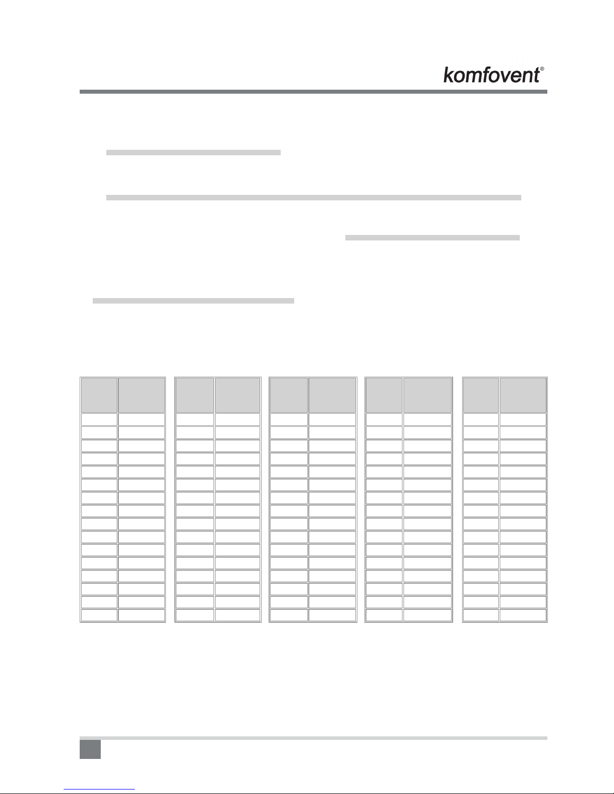
Indoor Temp. and Pipe Temp. Sensor Resistance Value
Appendix 1
Outdoor
Temp.
0C
Sensor
Resistance
kΩ
-20 115.266
-19 108.146
-18 101.517
-17 96.3423
-16 89.5865
-15 84.2190
-14 79.3110
-13 74.5360
-12 70.1698
-11 66.0898
-10 62.2756
-9 58.7079
-8 56.3694
-7 52.2438
-6 49.3161
-5 46.5725
Outdoor
Temp.
0C
Sensor
Resistance
kΩ
-4 44.0000
-3 41.5878
-2 39.8239
-1 37.1988
0 35.2024
1 33.3269
2 31.5635
3 29.9058
4 28.3459
5 26.8778
6 25.4954
7 24.1932
8 22.5662
9 21.8094
10 20.7184
11 19.6891
Outdoor
Temp.
0C
Sensor
Resistance
kΩ
12 18.7177
13 17.8005
14 16.9341
15 16.1156
16 15.3418
17 14.6181
18 13.9180
19 13.2631
20 12.6431
21 12.0561
22 11.5000
23 10.9731
24 10.4736
25 10.0000
26 9.55074
27 9.12445
Outdoor
Temp.
0C
Sensor
Resistance
kΩ
28 8.71983
29 8.33566
30 7.97078
31 7.62411
32 7.29464
33 6.98142
34 6.68355
35 6.40021
36 6.13059
37 5.87359
38 5.62961
39 5.39689
40 5.17519
41 4.96392
42 4.76253
43 4.57050
Outdoor
Temp.
0C
Sensor
Resistance
kΩ
44 4.38736
45 4.21263
46 4.04589
47 3.88673
48 3.73476
49 3.58962
50 3.45097
51 3.31847
52 3.19183
53 3.07075
54 2.95896
55 2.84421
56 2.73823
57 2.63682
58 2.53973
59 2.44677
This manual suits for next models
5
Table of contents
Other Komfovent Air Conditioner manuals


Popular Air Conditioner manuals by other brands

Fujitsu
Fujitsu ASYG 09 LLCA installation manual

York
York HVHC 07-12DS Installation & owner's manual

Carrier
Carrier Fan Coil 42B Installation, operation and maintenance manual

intensity
intensity IDUFCI60KC-3 installation manual

Frigidaire
Frigidaire FAC064K7A2 Factory parts catalog

Sanyo
Sanyo KS2432 instruction manual


Mitsubishi Electric
Mitsubishi Electric PUHZ-RP50VHA4 Service manual

Panasonic
Panasonic CS-S18HKQ Service manual

Panasonic
Panasonic CS-E15NKE3 operating instructions

Gree
Gree GWH18TC-K3DNA1B/I Service manual

Friedrich
Friedrich ZoneAire Compact P08SA owner's manual

Daikin
Daikin R32 Split Series installation manual