Komfovent MOU User manual

MOU
EN Installation Manual


UAB KOMFOVENT we reserve the right to make changes without prior notice.
MOU2-20-03 3
This symbol indicates that this product is not to be disposed of with your household waste, according to the
WEEE Directive (2002/96/EC) and your national law. This product should be handed over to a designated
collection point, or to an authorised collection site for recycling waste electrical and electronic equipment (EEE).
Improper handling of this type of waste could have a possible negative impact on the environment and human
health due to potentially hazardous substances that are generally associated with EEE. At the same time, your
cooperation in the correct disposal of this product will contribute to the eective usage of natural resources. For
more information about where you can drop o your waste equipment for recycling, please contact your local city
oce, waste authority, approved WEEE scheme or your household waste disposal service.
Content
1. SAFETY PRECAUTIONS ............................................................................................................................... 4
2. OUTDOOR UNIT INSTALLATION................................................................................................................. 5
2.1. Outdoor Unit Installation Instructions ......................................................................................................... 5
3. REFRIGERANT PIPING CONNECTION....................................................................................................... 8
3.1. Notes On Pipe Length and Elevation......................................................................................................... 8
3.2. Refrigerant Piping Connection Instructions................................................................................................ 8
4. PIPING DIAGRAMS.......................................................................................................................................11
5. WIRING .......................................................................................................................................................... 12
5.1. Outdoor Unit Wiring................................................................................................................................. 13
6. AIR EVACUATION......................................................................................................................................... 14
6.1. Evacuation Instructions............................................................................................................................ 14
6.2. Note On Adding Refrigerant..................................................................................................................... 15
7. OUTDOOR UNIT SPECIFICATIONS........................................................................................................... 16
8. AHU KIT SPECIFICATIONS KA8140/8141, KA8243/8245......................................................................... 17
8.1. Introduction .............................................................................................................................................. 17
8.2. Specication and packing list................................................................................................................... 17
8.3. System design.......................................................................................................................................... 18
8.4. Function and Setting ................................................................................................................................ 18
8.4.1. KA8140/KA8141........................................................................................................................... 18
8.4.2. KA8243/KA8245........................................................................................................................... 19
8.5. Control module connection to controller................................................................................................... 21
8.5.1. KA8140/KA8141 connection to C6............................................................................................... 21
8.5.2. KA8140/KA8141 connection to C6M............................................................................................ 21
8.5.3. KA8140/KA8141 connection to C5............................................................................................... 21
8.5.4. KA8140/KA8141 connection to C5 zone...................................................................................... 22
8.5.5. KA8243 KA8245 connection to C5............................................................................................... 22
8.5.6. KA8243/KA8245 connection to C5 zone...................................................................................... 22
8.6. Malfunction, Error Code and Solving steps.............................................................................................. 23
8.6.1. E1 solving step--communication error with outdoor unit .............................................................. 24
8.6.2. E2 – temp sensor malfunction...................................................................................................... 25
8.6.3. Ed – outdoor unit malfunction....................................................................................................... 25
8.7. Dimensions .............................................................................................................................................. 26
8.7.1. KA8140/KA814............................................................................................................................. 26
8.7.2. KA8243/KA8245........................................................................................................................... 26

EN
UAB KOMFOVENT we reserve the right to make changes without prior notice.
MOU2-20-03
4
1. SAFETY PRECAUTIONS
Read Safety Precautions Before Installation
Incorrect installation due to ignoring instructions can cause serious damage or injury. The seriousness of po-
tential damage or injuries is classied as either a WARNING.
Failure to observe a warning may result in death. The appliance must be
installed in accordance with national regulations. Failure to observe a
caution may result in injury or equipment damage.
• Carefully read the Safety Precautions before installation.
• Only trained and certied technicians should install, repair and ser-
vice this air conditioning unit. Improper installation may result in elec-
trical shock, short circuit, leaks, re or other damage to the equip-
ment and personal property.
• Strictly follow the installation instructions set forth in this manual. Im-
proper installation may result in electrical shock, short circuit, leaks,
re or other damage to the equipment.
• Before you install the unit, consider strong winds, typhoons and
earthquakes that might aect your unit and locate it accordingly.
Failure to do so could cause the equipment to fail.
• After installation, ensure there are no refrigerant leaks and that the
unit is operating properly. Refrigerant is both toxic and flammable
and poses a serious health and safety risk.
Note about Fluorinated Gasses
1. This unit contains fluorinated gasses. For specic information on the type of gas and the amount, please
refer to the relevant label on the unit itself.
2. Installation, service, maintenance and repair of this unit must be performed by a certied technician.
3. Product uninstallation and recycling must be performed by a certied technician.
4. If the system has a leak-detection system installed, it must be checked for leaks at least every 12 months.
5. When the unit is checked for leaks, proper record-keeping of all checks is strongly recommended.
UAB KOMFOVENT we reserve the right to make changes without prior notice.
MOU2-20-03 5
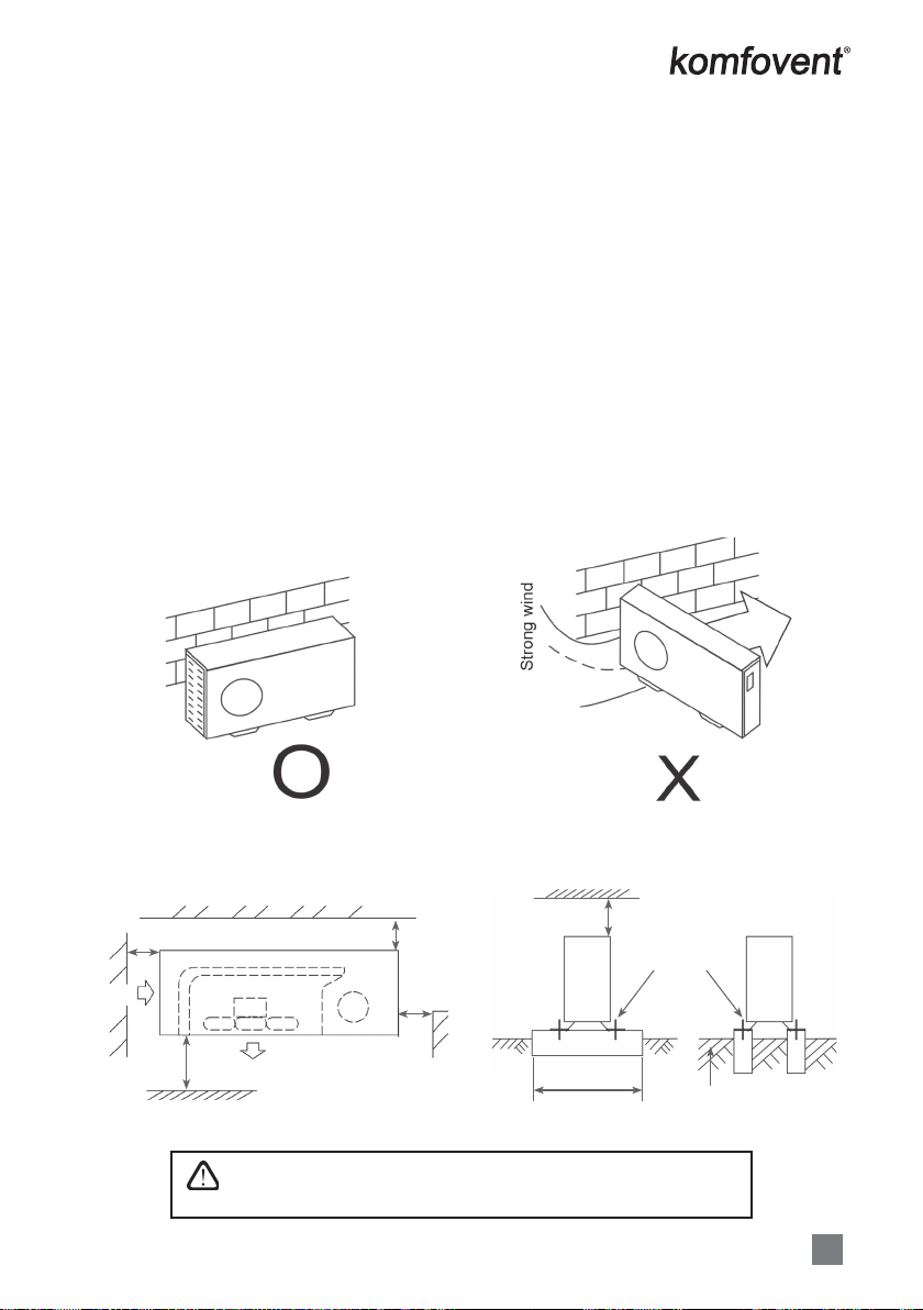
Fig. 2.1 Fig. 2.2
2. OUTDOOR UNIT INSTALLATION
2.1. Outdoor Unit Installation Instructions
Step 1: Select installation location.
The outdoor unit should be installed in the location that meets the following requirements:
• Place the outdoor unit as close to the indoor unit as possible.
• Ensure that there is enough room for installation and maintenance.
• The air inlet and outlet must not be obstructed or exposed to strong wind.
• Ensure the location of the unit will not be subject to snowdrifts, accumulation of leaves or other seasonal
debris. If possible, provide an awning for the unit. Ensure the awning does not obstruct airflow.
• The installation area must be dry and well ventilated.
• There must be enough room to install the connecting pipes and cables and to access them for maintenance.
• The area must be free of combustible gases and chemicals.
• The pipe length between the outdoor and indoor unit may not exceed the maximum allowable pipe length.
• If possible, DO NOT install the unit where it is exposed to direct sunlight.
• If possible, make sure the unit is located far away from your neighbors’ property so that the noise from the
unit will not disturb them.
• If the location is exposed to strong winds (for example: near a seaside), the unit must be placed against the
wall to shelter it from the wind. If necessary, use an awning. (See Fig. 2.1 & 2.2)
• Install the indoor and outdoor units, cables and wires at least 1 meter from televisions or radios to prevent
static or image distortion. Depending on the radio waves, a 1 meter distance may not be enough to eliminate
all interference.
Step 2: Install outdoor unit.
Fix the outdoor unit with anchor bolts (M10)
5
Outdoor Units
Outdoor unit installation
Cautions
.HHSWKLVXQLWDZD\IURPGLUHFWUDGLDWLRQRIWKHVXQRURWKHUKHDWHUV
,IXQDYRLGDEOHSOHDVHFRYHULWZLWKDVKHOWHU
,QSODFHVQHDUFRDVWRUZLWKDKLJKDWWLWXGHZKHUHWKHZLQGLVYLROHQWSOHDVHLQVWDOOWKHRXW-
GRRUXQLWDJDLQVWWKHZDOOWRHQVXUHQRUPDOSHUIRUPDQFH
8VHDEDIÀHZKHQQHFHVVDU\
,QWKHFDVHRIH[WUHPHO\VWURQJZLQGSOHDVHSUHYHQWWKHDLUIURPÀRZLQJEDFNZDUGVLQWRWKH
outdoor unit. ( Refer to chart 16)
Locate the outdoor unit as close to the indoor unit as possible.
7KHPLQLPXPGLVWDQFHEHWZHHQWKHRXWGRRUXQLWDQGREVWDFOHVGHVFULEHGLQWKHLQVWDOODWLRQ
chart does not mean that the same is applicable to the situation of an airtight. Leave open
WZRRIWKUHHGLUHFWLRQV$%&
Necessary room for installation and maintenance
5HIHUWRFKDUWFKDUW
,ISRVVLEOHSOHDVHUHPRYHWKHREVWDFOHVQHDUE\WRSUHYHQWWKHSHUIRUPDQFHIURPEHLQJLPSHGHGE\WRROLWWOH
of air circulation.
7KHPLQLPXPGLVWDQFH EHWZHHQWKHRXWGRRUXQLW DQGREVWDFOHVGHVFULEHGLQ WKHLQVWDOODWLRQFKDUWGRHVQRW
PHDQ WKDW WKH VDPH LV DSSOLFDEOH WR WKH VLWXDWLRQ RI DQ DLUWLJKW URRP /HDYH RSHQ WZR RI WKH WKUHH GLUHFWLRQV
$%&
Chart 1
6WURQJZLQG
Wall or obstacle
Air inlet
Air inlet
>30 cm
>60 cm
C
Air outlet
>200 cm
A
>30 cm
Chart 2
Maintain channel
Chart 3
>60 cm
1HFHVVDU\ZLGWK
)L[ZLWKEROW
Deep foundation
Fig. 2.3
• Be sure to remove any obstacles that may block air circulation.
• Make sure you refer to Length Specications to ensure there is
enough room for installation and maintenance.
This manual suits for next models
6
Table of contents
Other Komfovent Air Conditioner manuals


Popular Air Conditioner manuals by other brands

Fujitsu
Fujitsu ASYG 09 LLCA installation manual

York
York HVHC 07-12DS Installation & owner's manual

Carrier
Carrier Fan Coil 42B Installation, operation and maintenance manual

intensity
intensity IDUFCI60KC-3 installation manual

Frigidaire
Frigidaire FAC064K7A2 Factory parts catalog

Sanyo
Sanyo KS2432 instruction manual


Mitsubishi Electric
Mitsubishi Electric PUHZ-RP50VHA4 Service manual

Panasonic
Panasonic CS-S18HKQ Service manual

Panasonic
Panasonic CS-E15NKE3 operating instructions

Gree
Gree GWH18TC-K3DNA1B/I Service manual

Friedrich
Friedrich ZoneAire Compact P08SA owner's manual

Daikin
Daikin R32 Split Series installation manual