manuals.online logo
Brands
  1. Home
  2. •
  3. Brands
  4. •
  5. Komfovent
  6. •
  7. Air Handler
  8. •
  9. Komfovent DOMEKT C6M automation User manual

Komfovent DOMEKT C6M automation User manual

Other Komfovent Air Handler manuals

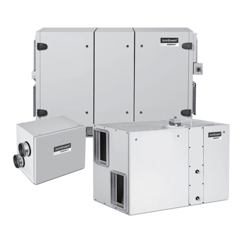
Komfovent RHP Standard User manual

Komfovent

Komfovent RHP Standard User manual

Komfovent KOMPAKT REGO User manual

Komfovent

Komfovent KOMPAKT REGO User manual

Komfovent DOMEKT series User manual

Komfovent

Komfovent DOMEKT series User manual

Komfovent DOMEKT C8 automation User manual

Komfovent

Komfovent DOMEKT C8 automation User manual

Komfovent RECU 300VE-B-AC User manual

Komfovent

Komfovent RECU 300VE-B-AC User manual

Komfovent RHP Pro2 User manual

Komfovent

Komfovent RHP Pro2 User manual

Komfovent DOMEKT R 200 VSO C8 User manual

Komfovent

Komfovent DOMEKT R 200 VSO C8 User manual

Komfovent Verso Pro 2 Series User manual

Komfovent

Komfovent Verso Pro 2 Series User manual

Komfovent Domekt REGO User manual

Komfovent

Komfovent Domekt REGO User manual

Komfovent DOMEKT RHP 400 U-2.8/2.4 User manual

Komfovent

Komfovent DOMEKT RHP 400 U-2.8/2.4 User manual

Komfovent KOMPAKT REGO Series User manual

Komfovent

Komfovent KOMPAKT REGO Series User manual

Komfovent KLASIK Series User manual

Komfovent

Komfovent KLASIK Series User manual

Komfovent KOMPAKT Recu User manual

Komfovent

Komfovent KOMPAKT Recu User manual

Komfovent DOMEKT series Manual

Komfovent

Komfovent DOMEKT series Manual

Komfovent RHP Pro User manual

Komfovent

Komfovent RHP Pro User manual

Komfovent Domekt S User manual

Komfovent

Komfovent Domekt S User manual

Komfovent RHP Pro2 User manual

Komfovent

Komfovent RHP Pro2 User manual

Komfovent VERSO Standard User manual

Komfovent

Komfovent VERSO Standard User manual

Komfovent RHP Series User manual

Komfovent

Komfovent RHP Series User manual

Komfovent VERSO Standard Manual

Komfovent

Komfovent VERSO Standard Manual

Komfovent MOU Series User manual

Komfovent

Komfovent MOU Series User manual

Popular Air Handler manuals by other brands

Vents VUT 270 V5B EC A14 user manual

Vents

Vents VUT 270 V5B EC A14 user manual

Armstrong Air BCE7S Series installation instructions

Armstrong Air

Armstrong Air BCE7S Series installation instructions

Klimor EVO-S Operation and maintenance manual

Klimor

Klimor EVO-S Operation and maintenance manual

Salda SMARTY XP MOUNTING AND INSTALLATION INSTRUCTION

Salda

Salda SMARTY XP MOUNTING AND INSTALLATION INSTRUCTION

BLAUBERG KOMFORT Roto EC S400 user manual

BLAUBERG

BLAUBERG KOMFORT Roto EC S400 user manual

Trenton TPLP Series installation instructions

Trenton

Trenton TPLP Series installation instructions

Daikin DV PTC 14 Series installation instructions

Daikin

Daikin DV PTC 14 Series installation instructions

Haier HB2400VA1M20 Installation & operation manual

Haier

Haier HB2400VA1M20 Installation & operation manual

Webasto BlueCool A-Series operating instructions

Webasto

Webasto BlueCool A-Series operating instructions

RDZ DA 701 Technical installation manual

RDZ

RDZ DA 701 Technical installation manual

Carrier 39T Installation, Start-Up and Service Instructions

Carrier

Carrier 39T Installation, Start-Up and Service Instructions

Armstrong Air BCE5V Series installation instructions

Armstrong Air

Armstrong Air BCE5V Series installation instructions

Carrier 40MBDAQ Service manual

Carrier

Carrier 40MBDAQ Service manual

TemperZone Econex Pro OPA 1410RLTM4FPQD Installation & maintenance

TemperZone

TemperZone Econex Pro OPA 1410RLTM4FPQD Installation & maintenance

RDZ WHR 200 Technical installation manual

RDZ

RDZ WHR 200 Technical installation manual

AAON H3 Series Installation operation & maintenance

AAON

AAON H3 Series Installation operation & maintenance

Lennox VEOA042N432U Installation & operation instructions

Lennox

Lennox VEOA042N432U Installation & operation instructions

Kemper CleanAirTower operating manual

Kemper

Kemper CleanAirTower operating manual

manuals.online logo
manuals.online logoBrands
  • About & Mission
  • Contact us
  • Privacy Policy
  • Terms and Conditions

Copyright 2025 Manuals.Online. All Rights Reserved.

EN
INSTALLATION
MANUAL
DOMEKT
C6M automation
EN
UAB KOMFOVENT we reserve the right to make changes without prior notice
DOMEKT_C6M_installation manual_23-022
CONTENT
1. INTRODUCTION ...........................................................................................................................................................................................................3
1.1. Safety requirements ............................................................................................................................................................................................3
1.2. Design of the units...............................................................................................................................................................................................4
1.3. Components...........................................................................................................................................................................................................6
1.3.1. Horizontal units.........................................................................................................................................................................................6
1.3.2. Vertical units...............................................................................................................................................................................................8
1.3.3. Flat units.......................................................................................................................................................................................................9
2. UNIT TRANSPORTATION AND STORAGE......................................................................................................................................................11
3. MECHANICAL INSTALLATION............................................................................................................................................................................12
3.1. List of parts in the package............................................................................................................................................................................12
3.2. Installation site requirements.......................................................................................................................................................................12
3.2.1. Maintenance area..................................................................................................................................................................................13
3.2.2. Humidity in the installation room ...................................................................................................................................................14
3.3. Unit dimensions.................................................................................................................................................................................................16
3.3.1. Vertical units............................................................................................................................................................................................16
3.3.2. Horizontal units......................................................................................................................................................................................17
3.3.3. Flat units....................................................................................................................................................................................................17
3.4. Location and dimensions of xture elements ........................................................................................................................................ 18
3.5. Duct system installation..................................................................................................................................................................................19
3.6. Connection of external heating/cooling units ....................................................................................................................................... 22
3.7. Connection of condensate drain................................................................................................................................................................. 23
4. ELECTRICAL INSTALLATION ............................................................................................................................................................................... 24
4.1. Electrical input requirements........................................................................................................................................................................ 24
4.2. Connecting electrical components ............................................................................................................................................................24
4.3. Control panel installation...............................................................................................................................................................................27
4.4. Connecting the unit to an internal computer network or the Internet.........................................................................................29
5. STARTING AND CHECKING THE UNIT............................................................................................................................................................ 31
5.1. Control panel C6.1.............................................................................................................................................................................................32
5.2. Control panel C6.2.............................................................................................................................................................................................33
5.3. Start-up of the unit using a computer....................................................................................................................................................... 33
5.4. Quick check .........................................................................................................................................................................................................35
UAB KOMFOVENT we reserve the right to make changes without prior notice
DOMEKT_C6M_installation manual_23-02 3
1. INTRODUCTION
This manual is intended for qualied technicians installing the DOMEKT air handling unit. Qualied professionals are per-
sons with sucient professional experience and knowledge of ventilation systems, their installation, knowledge of electrical
safety requirements and ability to work without risk to themselves or others.
1.1. Safety requirements
To avoid misunderstandings, read this manual carefully before installing the unit.
Air handling unit may only be installed by a qualied technician in accordance with the instructions given in this manual
and in accordance with applicable legal and safety requirements. The air handling unit is an electrical-mechanical device
that contains electrical and moving parts, therefore, ignoring the instructions in the manual not only shall invalidate the
manufacturer’s warranty but can also cause direct damage to property or human health.
• When performing any kind of work, make sure the unit is unplugged from electrical supply.
• Use caution when working near heaters inside or outside the unit, as their surfaces may be hot.
• Do not connect the unit to the power supply network before all the external assemblies are fully
installed.
• Do not connect the unit to the electrical supply, if there is visible damage that occurred during
transport.
• Do not leave objects or tools inside the unit.
• It is forbidden to operate the unit in the premises where there is a risk of release of explosive
substances.
• Use appropriate personal protective equipment (gloves, goggles) when installing or repairing the
unit.
This sign means that the product may not be disposed of together with your household waste as dened in Directive
(2002/96/EC) and national legislation on the management of WEEE. This product must be disposed of at an appropri-
ate collection point or recycling facility for waste electrical and electronic equipment (WEEE). Improper handling of
this type of waste due to hazardous substances inside electrical and electronic equipment can endanger the environ-
ment and human health. By helping to ensure proper disposal of this product, you will also contribute to the ecient
use of natural resources. For more information on how to dispose of such waste for further recycling, contact your city
authorities, waste management organisations, approved WEEE systems or your household waste management bodies
representatives.
EN
UAB KOMFOVENT we reserve the right to make changes without prior notice
DOMEKT_C6M_installation manual_23-024
1.2. Design of the units
Domekt CF is an air handling unit with a counter-ow recuperator (heat exchanger). Lamellas of the heat exchange come
in contact with dierent air ows. Exchange of heat or cold takes place between extracted indoor and fresh outdoor air. If no
recuperation is required, the air bypass damper is opened and the heat exchanger is closed. This way the outdoor air passes
around the recuperator and enters the premises directly.
Counter-ow heat
exchanger
Air ter
Air ter
Air bypass
Fan
Fan Heater or
cooler
OUTDOOR
ROOM
Rotary heat
exchanger
Fan Air ter
Fan Heater or
cooler
Air ter
OUTDOOR
ROOM
Domekt R – air handling units with a rotary recuperator (heat exchanger). The rotating drum of the rotary recuperator
absorbs heat or cold from the air of the premises, transferring it to the fresh outdoor air. If recuperation is not required, the
rotation of the rotary heat exchanger is stopped.
Counter-ow heat
exchanger
Air ter
Air ter
Air bypass
Fan
Fan Heater or
cooler
OUTDOOR
ROOM
Rotary heat
exchanger
Fan Air ter
Fan Heater or
cooler
Air ter
OUTDOOR
ROOM
If the capacity of the heat exchanger is not sucient to reach the temperature set by the user, heaters
or coolers may additionally be switched on1. Heat exchanger and heater (or cooler) are designed to com-
pensate for heating/cooling losses during the ventilation of the premises, thus AHU is not recommended
to be used as main heating/cooling source of the building. AHU may not reach the supply temperature
setpoint if the actual room temperature diers a lot from the desired value, since in that case heat ex-
changer capacity will be low.
1 Depends on the unit components.
UAB KOMFOVENT we reserve the right to make changes without prior notice
DOMEKT_C6M_installation manual_23-02 5

Depending on the installation and connection of the ducts, the air handling units are divided into:
• Vertical units – when all ducts are connected at the top.
• Horizontal units – when all ducts are connected on the sides.
• Flat units – thinner units are designed for mounting over suspended ceilings. All ducts are connected at the sides of the unit.
Horizontal unit Vertical unit Flat unit
Fig. 1. Classication of units by duct connection
Also, each unit may be left or right inspection side1. The inspection side indicates which side of the unit contains the air
supply duct to the premises.
Air duct to the
premises
Right inspection side Left inspection side Right inspection side Left inspection side
Air duct to the
premises
Vertical unit Horizontal or at unit
Fig. 2. Classication of units by inspection side
1 Depends on your order. The exact duct location is shown in the following paragraphs: «Components», «Unit dimensions».
EN
UAB KOMFOVENT we reserve the right to make changes without prior notice
DOMEKT_C6M_installation manual_23-026
1.3. Components
Below are the principal diagrams of air handling units, including the marking of assemblies of the unit.
1.3.1. Horizontal units
Domekt R 400 H
RIGHT
INSPECTION
SIDE
ETB
ETB
ODA
EHA
SUP
ETA
ODA
EHA
SUP
ETA
10 23 4
6 7
11 10
2 3
467 11
LEFT
INSPECTION
SIDE
Domekt R 600 H
RIGHT
INSPECTION
SIDE
10 23 4
6 7
11
ETB
ODA
EHA
SUP
ETA
ETB
ODA
EHA
SUP
ETA
10
2 3
46
711
LEFT
INSPECTION
SIDE
EHA
ODA
ETA
SUP
ETB
ETH
– outdoor air
– supply air
– extract air
– exhaust air
– by-pass extraction
without heat recovery
1– counter-ow heat exchanger
2– supply air fan
3– extract air fan
4– electric heater
5– electric pre-heater
6– outdoor air lter
7– extract air lter
8– condensate drainage
9– air bypass damper
10 – rotary heat exchanger
11 – C6M controller main board
UAB KOMFOVENT we reserve the right to make changes without prior notice
DOMEKT_C6M_installation manual_23-02 7
Domekt R 700 H
RIGHT
INSPECTION
SIDE
ETB
ODA
EHA
SUP
ETA
10 23 4
6 7
11 10
2 3
467 11
ETB
EHA
SUP
ETA
ODA
LEFT
INSPECTION
SIDE
Domekt CF 700 H
RIGHT
INSPECTION
SIDE
1 1 2
3 45
6 7
8 9 11 112 34 5 6
789
11
ODA
EHA
ETA
SUP
ODA
EHA
ETA
SUP
LEFT
INSPECTION
SIDE
EHA
ODA
ETA
SUP
ETB
ETH
– outdoor air
– supply air
– extract air
– exhaust air
– by-pass extraction
without heat recovery
1– counter-ow heat exchanger
2– supply air fan
3– extract air fan
4– electric heater
5– electric pre-heater
6– outdoor air lter
7– extract air lter
8– condensate drainage
9– air bypass damper
10 – rotary heat exchanger
11 – C6M controller main board
EN
UAB KOMFOVENT we reserve the right to make changes without prior notice
DOMEKT_C6M_installation manual_23-028
1.3.2. Vertical units
Domekt CF 200 V  CF 300 V Domekt R 400 V  R 450 V
EHA
ODA ETA
SUP
EHAODA SUPETA
EHA
ODA
ETA
SUP
EHA ODASUP ETA
89 6 8 96
1
4
5
3
7
11
2
ETA
SUP
EHA
ODA
ETB
SUP
ETA
ODA
EHA
ETB
SUP ETA
ETB
EHA ODA
SUP ETA
ETB
EHA ODA
3611
10 7243
6
11 10
7
2
4
RIGHT INSPECTION SIDE LEFT INSPECTION SIDE RIGHT INSPECTION SIDE LEFT INSPECTION SIDE
Domekt CF 400 V DOMEKT R 600 V  R 700 V  R 900 V
EHA SUP
ODA ETA
SUP EHA
ETA ODA
1
2
3
11
4
5
6
7
8
ODA EHA ETA SUP ETA SUP ODA EHA
2
3
4
6
7
11
10
ODA
EHA
ETB ETA
SUP
SUP
ODA ETAETB
EHA SUP ETA ETH ETB ODA
ODA
EHA
ETB
ETA
SUP
RIGHT INSPECTION SIDE LEFT INSPECTION SIDE RIGHT INSPECTION SIDE LEFT INSPECTION SIDE
Domekt CF 700 V
EHA
ODA
ETA
SUP
EHA ODA ETA
C6M C6M
SUP EHA
ODA
ETA
SUP
2
3
4
9
5
1
8
7
11
6
AHE
ADO
ATE
SUP
RIGHT INSPECTION SIDE LEFT INSPECTION SIDE
1– counter-ow heat exchanger
2– supply air fan
3– extract air fan
4– electric heater
5– electric pre-heater
6– outdoor air lter
7– extract air lter
8– condensate drainage
9– air bypass damper
10 – rotary heat exchanger
11 – C6M controller main board
EHA
ODA
ETA
SUP
ETB
ETH
– outdoor air
– supply air
– extract air
– exhaust air
– by-pass extraction without heat recovery
UAB KOMFOVENT we reserve the right to make changes without prior notice
DOMEKT_C6M_installation manual_23-02 9
1.3.3. Flat units
Domekt CF 150 F
RIGHT
INSPECTION
SIDE
SUP
ETA
EHA
ODA
12 547 68 9 3
11
SUP
ETA
EHA
ODA
125 4 76 8 9 11
3
LEFT
INSPECTION
SIDE
Domekt CF 500 F
RIGHT
INSPECTION
SIDE
M6C
M6C
1 1 7
6 2
3 4
11
9
58 1
1
762 34 11
9
5
8
ODA
EHA
ETA
SUP
ODA
EHA
ETA
SUP
LEFT
INSPECTION
SIDE
Domekt CF 700 F
RIGHT
INSPECTION
SIDE
1
3 45
678 9 2
11
ODA
EHA
ETA
SUP
M6C
1
3
456
7
8
9
211
ODA
EHA
ETA
SUP
M6C
LEFT
INSPECTION
SIDE
EHA
ODA
ETA
SUP
ETB
ETH
– outdoor air
– supply air
– extract air
– exhaust air
– by-pass extraction
without heat recovery
1– counter-ow heat exchanger
2– supply air fan
3– extract air fan
4– electric heater
5– electric pre-heater
6– outdoor air lter
7– extract air lter
8– condensate drainage
9– air bypass damper
10 – rotary heat exchanger
11 – C6M controller main board
EN
UAB KOMFOVENT we reserve the right to make changes without prior notice
DOMEKT_C6M_installation manual_23-0210
Domekt R 400 F
RIGHT
INSPECTION
SIDE
ODA
EHA
ETB
SUP
ETA
ETB
ODA
EHA
SUP
ETA
10 10 23 4
6 7
11 10 10
2 3
467 11
LEFT
INSPECTION
SIDE
Domekt R 700 F
RIGHT
INSPECTION
SIDE
10 23 4
6 7
11
10
ETB
EHA
SUP
ETA
10
2 3
467
ETB
ODA
EHA SUP
ETA
10 23 4
6 7
11
10 11 10
ODA
LEFT
INSPECTION
SIDE
EHA
ODA
ETA
SUP
ETB
ETH
– outdoor air
– supply air
– extract air
– exhaust air
– by-pass extraction
without heat recovery
1– counter-ow heat exchanger
2– supply air fan
3– extract air fan
4– electric heater
5– electric pre-heater
6– outdoor air lter
7– extract air lter
8– condensate drainage
9– air bypass damper
10 – rotary heat exchanger
11 – C6M controller main board