Konica Minolta IC-412 User manual

E-1
INSTALLATION MANUAL
A0YE-9550-01
VI-505/IC-412 Video Interface Kit/Image Controller
I. Accessory parts
Before starting to set up, check that the following are
included.
Only the parts required to install the image controller
appear in the package contents list.
Package contents of the image controller Fiery
IC-412
*1 This power cord is not used when installing the
image controller.
*2 This power cord cannot be used in Taiwan that
utilizes 110V power.
*3 The accessories are not used when installing
the image controller.
Package contents of the video interface kit
VI-505
* Using or not using the part depends on each
market.
No. Name Shape Q’ty
1. Image
controller
1
2. Power cord *1
1
3. Power cord *2
(for the wall
outlet) 1
4. Copier
LAN cable
(crossover
cable)
1
5. Image
transmission
cable 1
6. Ferrite Core
1
7. Other accesso-
ries *3 --
A0YEIXC001DA
A00HIXC019HA
A00HIXE034HA
A00HIXC018HA
A0YEIXC003DA
A0YEIXC054DA
No. Name Shape Q’ty
1. Relay circuit
board
1
2. Power cord *
(For connection
between copier
and IC) 1
3. Screw *
(4 × 8 mm) 1
4. Shoulder
screws for
mounting the
relay circuit
board
2
5. Shoulder
screws for the
relay circuit
board connec-
tor
2
6. Installation
manual
1 set
After unpacking, be sure to get rid of the
packaging materials and keep them out of
the reach of children.
Putting the head in the plastic bag
involves danger of suffocation.
A0YEIXC004DA
A0YEIXC002DA
4040IXC046DA
A0YEIXC005DB
A0YEIXC047DA
4980IXC019DA
Applied Machines: C652/C552/C452
COLOR MFP: 65 ppm/55 ppm/45 ppm
Product Code: A0P0/A0P1/A0P2

E-2
II. Part names
<Softswitch>
• Lights up when the image controller is running or
is ready to be used.
• When turned on, the image controller system
starts up.
• When turned off, the image controller system
safely shuts down.
Note:
• If the image controller malfunctions or cannot
be shut off with the softswitch, be sure to
unplug the power cord from the electrical outlet
or the machine’s power cord connector.
• Remove the seal from the connector of the
power cord.
<Port descriptions>
Port 1 (For the LAN)
Connect the network cable to the LAN.
Port 2 (For the COPIER)*
Use a crossover cable to connect to the LAN port of
the copier.
* This port is not used, depending on the connec-
tion method. Refer to page E-8.
III. Installation procedures
1. Turn off the machine and unplug the power cord
from the power outlet.
2. Remove the right side rear upper cover from the
copier (three screws).
3. If the fax kit has been installed, loosen the two
screws, and then remove the circuit board from
the copier.
A0YEIXC006DA
Ethernet 10Base-T/100Base-TX/1000Base-T
network port (Port 1)
Copier LAN cable port (Port 2)
Softswitch LED Image transmission
connector
Power
cord con-
nector
LAN COPIER
A00HIXC033HB
Port 1
Port 2
A0YEIXC008DB
A0YEIXC009DA

E-3
4. Remove the rear right cover (four screws).
5. Remove the internal bracket (11 screws).
6. Remove the interface connector cover for the
copier (one screw).
(Do not use the removed connector cover.)
7. Remove the two screws for the main circuit
board.
Note:
The two screws removed here will be used to
install the relay circuit board.
8. Attach the two supplied shoulder screws for
mounting the relay circuit board to the main cir-
cuit board.
9. Mount the supplied relay circuit board as shown
in the illustration.
A0YEIXC011DC
A0YEIXC012DB
A0YEIXC013DB
A0YEIXC014DA
A0YEIXC015DB
A0YEIXC016DA

E-4
10. While aligning the matchmarks on the relay cir-
cuit board and the main circuit board, connect
the connector coming from the back side of the
relay circuit board to the connector on the main
circuit board.
11. Using the two screws, secure the relay circuit
board.
Note:
Be sure to use the two screws removed in step 7.
12. Using the two supplied shoulder screws for the
relay circuit board connector, secure the connec-
tor of the relay circuit board.
13. Reinstall the internal bracket that has been
removed in step 5 (11 screws).
14. Reinstall the rear right cover that has been
removed in step 4 (four screws).
15. If the fax kit was removed in step 3, install it at
the location from where it was removed.
16. Remove the rear lower cover (six screws).
17. Remove the right side rear lower cover (two
screws).
18. Remove the center cover from the right side rear
lower cover removed in step 17 (two screws).
A0YEIXC041DA
A0YEIXC017DA
A0YEIXC018DA
A0YEIXC042DA
A0YEIXC046DA
A0YEIXC043DA

E-5
19. Remove the two brackets from the copier (two
screws each).
Note:
The four screws removed here will be used to
install the image controller.
<Attaching the image controller to C652 in all
regions and C552/C452 in regions that utilize 127 to
240V power>
* When attaching the image controller to C552/
C452 in regions that utilize 110 to 120V power,
follow the step 20 in page E-6 and later.
20. Remove the connector cover from the rear lower
side of the copier. The connector cover is shown
by the arrow in the illustration below.
21. Connect the supplied power cord (for connection
between copier and IC) to the connector.
22. Insert the harness into the wire saddle.
23. Fix the end of the ground wire included in the
power cord (for connection between copier and
IC) to the copier (screw furnished with the video
interface kit).
24. Install the image controller on the copier (four
screws).
Note:
Be sure to use the four screws removed in step
19.
A0YEIXC044DA
A0YEIXE036DA
A0YEIXE051DA
Power cord
A0YEIXE052DA
Wire saddle
A0YEIXE053DA
A0YEIXE038DB
Threaded hole

E-6
25. Connect the other end of the power cord to the
connector on the image controller.
Note:
No need to secure the connector of the power cord
with the clamp.
26. Connect the supplied image transmission cable
to the copier.
27. Attach the supplied ferrite core to the indicated
position on the image transmission cable.
28. Reinstall the right side rear upper cover removed
in step 2 (three screws).
29. Reinstall the right side rear lower cover removed
in step 17 (two screws).
30. Connect the other end of the image transmission
cable to the image controller.
31. Close the right side rear upper/lower covers.
32. Reinstall the rear lower cover that has been
removed in step 16 (six screws).
33. Plug the copier power cord into a power outlet.
<When attaching the image controller to C552/C452
in regions that utilize 110 to 120V power>
20. Install the image controller on the copier (four
screws).
Note:
Be sure to use the four screws removed in step
19.
A0YEIXE039DA
A0YEIXC026DA
A0YEIXC055DA
A0YEIXE040DA
A0YEIXC029DB
Threaded hole

E-7
21. Plug the supplied power cord (for the wall outlet)
into the power cord connector on the image con-
troller, and then secure the cord with the clamp.
Note:
• Be sure to use the supplied power cord (for the
wall outlet).
• Power cord for Taiwan that utilizes 110V power
is not supplied as an accessory part.
22. Connect the supplied image transmission cable
to the copier.
23. Attach the supplied ferrite core to the indicated
position on the image transmission cable.
24. Reinstall right side rear upper cover removed in
step 2 (three screws).
25. Reinstall the right side rear lower cover removed
in step 17 (two screws).
26. Connect the other end of the image transmission
cable to the image controller.
27. Close the right side rear upper/lower covers.
28. Remove the knockout plate from the cable pass-
through opening in the lower rear cover, and
then install the rear lower cover to the copier
(six screws).
29. Plug the copier and image controller power
cords into a power outlet.
IV. Specifying the copier settings
From the copier, specify the necessary settings for
using the image controller.
<Image Controller Settings>
1. Turn on the machine by using the auxiliary power
button and the main power switch.
2. Display the Service Mode screen.
(For details on displaying the screen, refer to the
Service Manual.)
3. Touch [System 2].
4. Touch [Image Controller Setting].
5. Touch [Controller 1].
6. Touch [END].
7. Touch [Exit].
8. Turn the copier off, then on again. (If the copier
has not been turned off, the setting changes are
not applied.)
A0YEIXC030DA
A0YEIXC026DA
A0YEIXC055DA
A0YEIXC031DB
A0YEIXC045DA

E-8
V. Connecting the copier and image con-
troller to a network
The network functions of the copier can be used
even when the image controller is installed.
There are two ways of connecting to a network from
this copier. When connection b is used, some func-
tions are limited.
Note:
Use a network cable (Category 5E or later recom-
mended) to connect to a computer.
a: Connecting the copier and image controller
with separate LAN cables
• With this connection method, the network func-
tions of the copier are not impaired, and the
image controller functions are added.
• The IP address settings for the copier and image
controller are specified separately.
• In order to use the network functions of the
copier, the network settings on the copier must be
specified according to the functions to be used.
1. Use a network cable to connect the LAN port of
the copier to the hub (LAN).
2. Use a network cable to connect port 1 of the
image controller to the hub (LAN).
Note:
Depending on the connection method, the image
controller TCP/IP settings are different. For details,
refer to step 11 in “VI. Specifying basic image con-
troller settings (IP address)”.
b: Connecting the copier and image controller
with the supplied copier LAN cable (cross-
over cable), and connecting the image con-
troller to a hub (LAN)
With this connection method, the following copier
function limitations are applied.
• AppleTalk and IPX/SPX protocols
• IPv6, IPsec, browsing for file transmissions
(SMB), and replies to broadcasts
• The 1000Base-T network speed cannot be used.
These functions can be used from the image con-
troller.
The function limitations are not applied to the image
controller.
1. Use the supplied copier LAN cable (crossover
cable) to connect the LAN port of the copier to
port 2 of the image controller.
2. Use a network cable to connect port 1 of the
image controller to the hub (LAN).
<Copier Network Settings>
Since the IP address of the copier can be set from
the image controller, it is not necessary to specify
the IP address from the copier. The IP address of
the copier appears at the end of the Configuration
Sheet for the image controller. However, the DHCP
settings must be specified from the copier in order
for the copier and image controller to communicate
internally through the crossover cable.
• Specifying the copier DHCP setting
Utility mode - “Administrator Settings” - “Network
Settings” - “TCP/IP Settings” - “IPv4 Settings” -
“Auto Input” - “DHCP Settings” - “ON”
• In order to use the network functions of the
copier, the network settings on the copier must be
specified according to the functions to be used.
A0YEIXC034DA
Port 1
Port 2
Port 1
Port 2
A0YEIXC035DA

E-9
Note:
• When manually specifying the IP address of the
image controller
Since the IP address of the copier is one num-
ber higher than the IP address of the image
controller, consecutively numbered IP
addresses must be available.
(Example: Image controller: 192.168.1.10;
Copier: 192.168.1.11)
However, “xxx.xxx.xxx.255” cannot be specified
for the IP address of the image controller if it is
set manually.
• When using DHCP to specify the IP address of
the image controller
Use the IP address assigned by the DHCP
server for the IP address of the image controller
and copier
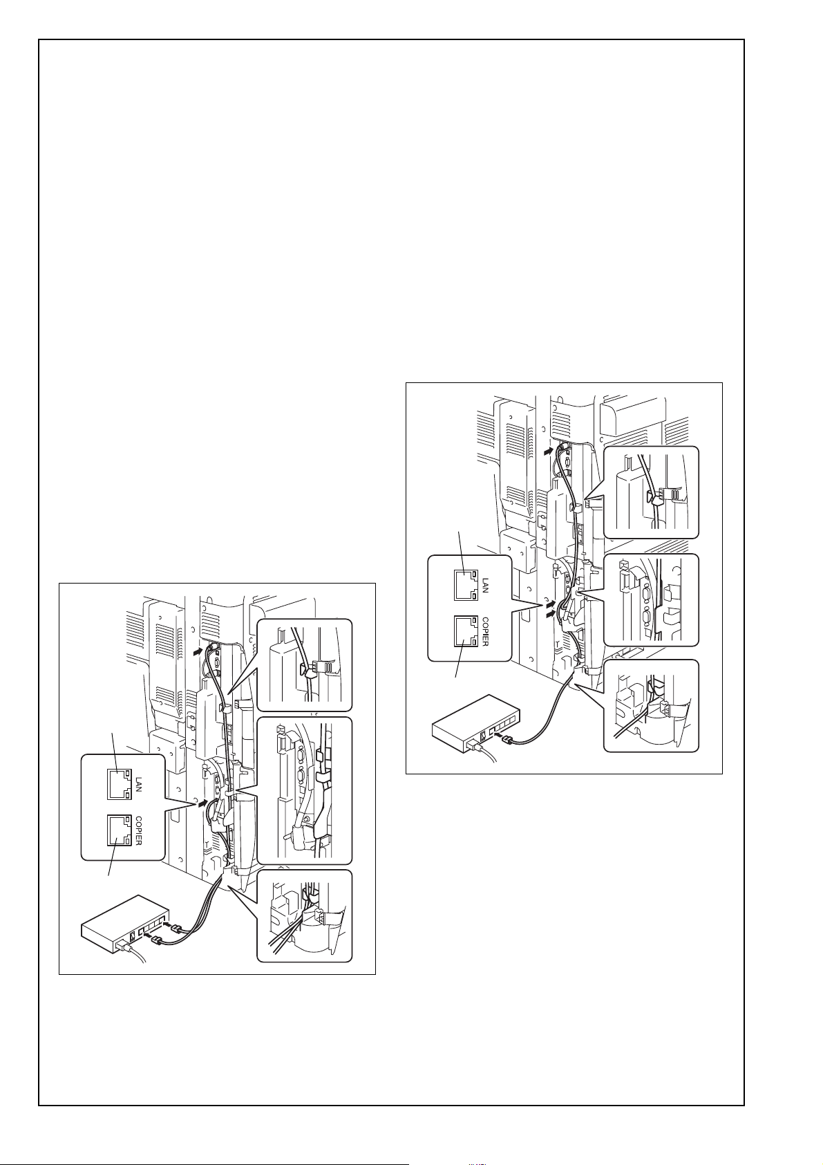
• Depending on the connection method, the
image controller TCP/IP settings are different.
For details, refer to step 11 in “VI. Specifying
basic image controller settings (IP address)”.
VI. Specifying basic image controller set-
tings (IP address)
Specify the default settings for the image controller.
1. Turn on the image controller.
2. Turn on the copier.
3. [Language Setup] appears in the lower center of
the screen in the copier’s touch panel.
4. Press the [Utility/Counter] key on the copier.
5. Touch [Controller Details].
Note:
If [Controller Details] does not appear, wait a short
while, and then repeat steps 3 and 4.
6. In the Language Setup screen, select the lan-
guage and market region.
After the settings have been specified, the con-
troller reboots.
7. When the password is entered, the Setup screen
appears. The default password is “Fiery.1”. (Be
sure to type in the password with the correct cap-
italization.)
8. Select “Server Setup” in the Controller Details
screen.
9. Without specifying any other settings, touch
[Exit]. When “Save Changes” appears, select
“Yes”, and then select “OK”.
10. In the same way, select “Network Setup”. After
selecting “Protocol Setup”, then “IPv4 Setup”,
select “Ethernet Setup”. Set “Enable AutoIP
Configuration” to “No”, and then select “OK”.
11. Specify settings for the following.
Note:
First check with your network administrator for the
settings that should be entered.
12. Touch [Menu] three times, select “Yes” when
“Save Changes” appears, and then select “OK”.
13. Touch [Printer Setup].
14. Touch [Menu], select “Yes” when “Save
Changes” appears, and then select “OK”.
15. When “Exit Setup” is selected, “Rebooting sys-
tem” appears and the image controller is
restarted.
16. After the image controller is ready to be used,
turn the copier off, then on again.
With this connection method, be careful of the tim-
ing for turning on the image controller and the
copier. For details on the timing, refer to the end of
this manual.
IP Address: Image controller IP address
Subnet Mask: Subnet mask for the con-
nected network
Gateway
Address:
IP address of the default
gateway
Obtain IP for
Engine:
Set whether to obtain the IP
address of the copier.
The setting is different
depending on the connec-
tion method used in
“V. Connecting the copier
and image controller to a
network”.
a: No
b: Yes
If “Yes” is selected, the IP
address of the copier
appears next to “Engine IP
Address” included in
“Device Information” on
Configuration Sheet.

E-10
VII. Checking the setup with a test print
After setting up the image controller, print the config-
uration sheet to check that the controller is operating
correctly.
<To print a test page>
1. Press the [Utility/Counter] key on the copier.
2. Touch [Controller Details].
3. Touch [Menu].
4. Select “Print Pages”.
The names of the pages that can be printed are
displayed.
5. Select “Configuration”.
Timing for turning on the copier with con-
nection method b from “V. Connecting the
copier and image controller to a network”
Turning on
Turn on the devices in the following order.
1. Turn on the softswitch on the image controller.
2. Check that the image controller is ready to be
used, and then turn on the copier.
Timing for turning on the copier
With connection b described in “V. Connecting the
copier and image controller to a network”, the copier
and image controller communicate internally through
a crossover cable.
If the DHCP function is enabled on the image con-
troller, the network interface card in the copier per-
forms a DHCP request when it is turned on in order
to acquire the IP address necessary for communi-
cating with the image controller.
Since a DHCP request is performed when the copier
is turned on, the IP address cannot be acquired if
the copier is turned on before the image controller is
ready to be used, preventing communications with
the image controller.
One of the following IP addresses can be assigned
to the copier.
172.17.249.2
10.249.249.2
If the copier is turned on too soon, a malfunction
may occur. For details, refer to the following infor-
mation.
This manual suits for next models
1
Table of contents
Other Konica Minolta Recording Equipment manuals