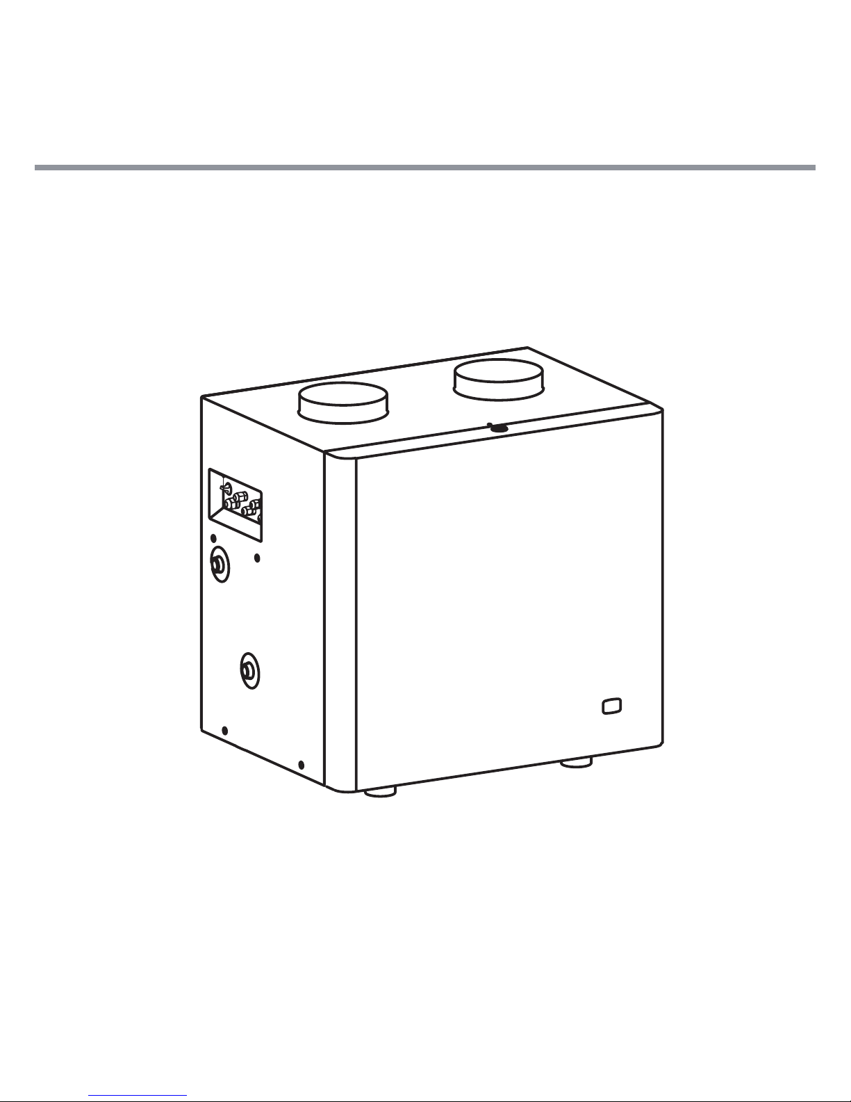
Kospel HPI-4 User manual

HEAT PUMP
HPI-4

2
Safety instructions
1. PleasereadandfollowtheInstallationandOperatingInstructionscarefully,to
ensurethelonglifeandreliableoperationofthisappliance.
2. Installationanduseofheatpumpinconsistentwiththisinstructionisnotpermit-
ted-maycausemalfunctionandwillvoidthewarranty.
3. Thedevicemustnotbeinstalledinunheatedrooms.
4. Theminimumairintaketemperature5°C.
5. Mountingandcommissioningoftheheatpumpandaccompanyinginstallation
shouldbeentrustedtoaspecialistservicecompany.
6. Theheatpumpshouldbeinstalledonlyinhorizontalpositiononaatsurface
withappropriateliftingcapacityoronasuitablesupportsonthewall.
7. The device must be installed in such a place and in a such a way that the
emergencyleakagefromconnectorswouldnotcauseoodingoftheroom.
8. Theroommusthaveapossibilitytodraincondensatetothesewer.
9. Aftersettingup,thedevicemustbeconnectedtothecylinderasdescribedin
containedmanual.Inconsistencewiththedescriptionoftheconnectioninvali-
datesthewarrantyandmaycausemalfunction.
10. The heat pump unit is designed to connect to installation with pressure not
exceeding0,6MPa.Ifthewaterpressureexceeds0,6MPa,installapressure
reducingvalveinfrontofthemachine.
11. Duringabreakinoperation,turnoffthedevicebyswitchingthepowerswitch
to„off”.Donotdisconnectthepowersupplyfromthedevice.
This appliance is not intended for use by persons (including children) with reduced physical,
sensory or mental capabilities or lack of experience and knowledge, unless they have been
given supervision or instruction concerning use of the appliance by a person responsible for
their safety. Children should be supervised to ensure that they do not play with the device.

3
GB-066B_f.
Description
The heat pump HPI-4 is used to heat sanitary water. The unit derives heat from
surroundingairandpassesthroughthewaterbyelectricallypoweredcompressor
refrigerantcircuit.
TheheatpumpHPI-4canbeusedtosupplywaterstoragetankswithacapacityof
100-400dm3.
[1] - air outlet
[2] - pipecross valve
[3] - air inlet
[4] - expansion valve
[5] - air lter
[6] - power button/power indication
[7] - water inlet G3/4”
[8] - pump
[9] - condenser
6
7
10 11
12
17
13 15
18
8
31
2
4
9
14
5
16
[10] - water outlet G3/4”
[11] - condensate outlet
[12] - compressor
[13] - pressure transducer
[14] - pressure switch
[15] - evaporator
[16] - vibro-isolator
[17] - heat pump driver
[18] - fan

4
Assembly
Theheatpumpshouldbeinstalledonlyinahorizontalpositiononaatsurfacewith
appropriateliftingcapacity.Thedevicecanalsobeboltedtobracketsmountedon
thewall.TofastenthedevicetothebracketsusescrewholesM10invibro-isolators.
Duringinstallation,ensureforgoodlevellingthedevicewhichwillallowforproper
drainageofcondensate.
414
100
380
min.200mm
min.400mm
min.400mm
Connection to the
hydraulic installation
Thedeviceisdesignedforco-operating
with hot water cylinder connected to
plumbing and protected against ex-
cessive pressure according to PN-76
/B-02440. The heat pump HPI-4 is a
pressuredeviceadaptedtoconnection
to plumbing pressure not exceeding
0,6MPa.At the inlet of water into the
device there should be installed a
strainer.
We recommend to connect
the device using hoses to eliminate
the transmission of vibrations to the
hydraulicsystem.
Inlet
Outlet
TZAS
hot
water
Cold
water
expansion vessel

5
GB-066B_f.
Air cables connection
Aircanbeextractedfromtheroomin
whichthedeviceismounted,another
roomorfromtheoutsideofthebuilding.
Inthesecondandthirdcase,thedevice
shouldresult in appropriate airducts.
Inthecasewheretheairintakeonthe
airoutletareononewallatadistance
oflessthan4meters,ontheairthere
mustbeamoulderdirectingairowin
adirectionoppositetotheairintake.At
theinletandairoutletthereareDN200
connectors.Theinstallationshouldbe
made of DN200 pipe using reducing
heatpumpttingsonaconnections.In
ordertoachieveoptimaldeviceparam-
eters,ensurethattheairowofat800
m3/h. To minimize losses associated
withairresistance,thecablemustbe
performedinastraightline.ForDN200
thetotallengthoftheinletandairoutlet
shouldnotexceed10m.Forwiringwith
thechangeofdirectionshouldbetaken
thattheresistanceofairowthrough
one knee correspond to the air ow
resistanceby2mpipe.Theseremarks
applytobendpipe.
Duringthewinter,wheretheairtemper-
atureoutsidecandropbelow0,thereis
ariskofwaterfreezinginthecirculation
pump and the hydraulic system. This
canleadtodamagesoftheelements
mentionedabove,inordertopreventit
ontheinletchannel-shut-offvalveof
airsupplyshouldbeinstalled.
air outlet
air inlet
Ø200
Ø200

6
Connecting of the
condensate hose
Duringnormaloperation,moistureintheaircondensesonthewallsofevaporator.
Condensatesowintothedriptraywhereareledtothetubenozzleontheoutside
ofthedevice.Duringtheoperationofthepump,fancreatesunderpressureinside,
toallowfreedrainageofcondensate,siphonshouldbeinstalledtothedrainpipe.
Air lter
1
2
3
Pullthepocketvigorouslyandmove
theltermaximumtotheright
Tilttheltertothebottomandpull
outofthehandle
Ontheinletofthedevicethereisanairltermounted,andatleastonceayearthe
cleannessshouldbecheckedandreplacedifnecessary.Designationoflter-pocket
lter287x287x200withltrationclassG3.

7
GB-066B_f.
Thedevicemustbeconnectedtotheelectricalsystemusingtheattachedcablesec-
tion3x1mm2endedwithaplug.
Theelectricalsystemshallbeequippedwitharesidualcurrentprotectivedevices.
Connection to the electric
installation
SG SW LED 485
KABA
TZAS
TS1 TS2 TP TD TG1 TG2 PS
+5 S G
NA
InordertoallowinteractionwithotherdevicesthedriverisequippedwithSGand
NAclamps.
SG(max.0,1A250V~)-relayoutputexcludingslavedevice;duringoperationofthe
heatpumpoutputcircuitconnectedtoSGisopen.
„NA”(inputvoltagefree)-inputofthemasterdevice;openingthecontactof„NA”
disablesstartingthedevice.Whileconnectingtotheclamps
„NA”the master device (eg. timeswitch or temperature regulator) switchpos. [6]
switchto„ON”,andinthecaseofconnectingtemperatureregulatortheN03setting
shouldbechangedto„OFF”positionandthenunplugTZASsensor.
ConnectingtheclampsSGandNAshouldbecarriedoutwith2x0,5mm2wire,leading
italongtheexistingelectricalwiringinsidetheunit.Connectionshouldbeperformed
byqualiedperson.
NA
Heat pump
NC
NO
COM
Temperature regulator
Before connecting the temperature controller remove the jumper on the input
NA of heat pump.

8
Start-up
Beforestartingtheunit,visuallychecktheconnectionofthedeviceandproperinstal-
lationinaccordancewiththediagrams.
Thetankmustbelledwithwater:
- openthevalveonthecoldwaterinlet,
- openthevalveonthehotwateroutletinstallation(fullowofthewaterstream,
withoutairbubblesindicatesthatthetankisfull,
- closethetaps.
Checkforleaksofthesanitaryhotwaterside.
Checktheoperationofthesafetyvalve(inaccordancewiththevalve’smanufacturer
instruction).
Checktheconnectionofairducts.
Checktheelectricalconnection.
Connecttheswitch[6]onthe“ON”position,theunitwillprocesswithfactorysettings.
The heat pump controller
The heat pump controller is located
underthecover.Toremovethecover
twistlocksontheupperandlowerpart
thereofasshownonthepicture.
Functions of the controller buttons:
a)
Selectionmodeofdisplayedinforma-
tion.
Indication markings:
B (ERRORS)-Errordisplaymode,
availableifthedevicediagnoses
thefault,
S (SERVICE)-servicemode,
N (SETTINGS)-settingmode
P (PREVIEW) - preview mode for
settings,
b) selectionoftheparameterorincreaseoftheparametervalue,
c) selectionoftheparameterordecreaseoftheparametervalue,
d) settingsmode,
e) display,
f) statusindicatorsofthedevice:

9
GB-066B_f.
ERR COM STAT
e
a
b
c
d
f
▲
▲
▲
B
S
N
P
P01 Temperatureofcylinder0°C,ifN03settingchosen-„off”displayedvalue„0”
P05 Intakeairtemperature°C
ERR error
COM communicationwiththemaster
device
STAT statusofthedevice
Change parameters of settings:
1. Select(a)settingmode(highlightedindicatorN),thensequentlyonthedisplay
willappearsettingnumberandsettingvalue.
2. Selectsettingusing(b)and(c).
3. Usingbutton(d)entersettingchangemode(indicatorNstartsashing).
4. Changesettingbyusing(b)and(c).
5. Usingbutton(d)exitchangesettingmode(indicatorNstopsashing).
N01 setpointtemperatureinthetank20-55°C-factorysetting50°C
N02
minimumtemperatureforthelowersource(air)5-15°C-factorysetting10°C
N03
deactivatingofthetemperaturesensorinthetank„on-off”factorysetting„on”
Modes B; S and P
areavailableforservicepurposes.

10
Technical data
Model HPI-4
Heatingpower(wgEN14511)
A20/W35
kW
3,7
A7/W35 3,0
A20/W45 3,4
A7/W45 2,7
COP(wgEN14511)
efciencyfactor
A20/W35
-
3,8
A7/W35 3,1
A20/W45 3,2
A7/W45 2,5
Powersupply ~V/Hz 230/50
Powerconsumption A 5,7
Numberofcompressors pcs. 1
Themaximumpressureoftherefrigerant
MPa 3,1
Refrigeranttype - R407C
Refrigerantvolume g 1250
Maximumwatertemperature °C 60
Ratedwaterpressure MPa 0,6
Waterowrate m3/h 0,6
Availablepumppressure kPa 15
Airow m3/h 800
Availablestaticpressure Pa 200
Surroundingtemperature °C 5÷40
Dimensions(HxWxD) mm 673x690x520
Weight kg 65
Noiselevel dB(A) 53

Thisproductmustnotbetreatedasacommunalwaste.Dismantledapplianceoughttobe
giventoanappropriaterecyclingpointforelectricalandelectronicwaste.Appropriatedisposal
oftheusedproductpreventspotentialnegativeinuenceontheenvironment,whichcould
occurincaseofanimproperwastedisposal.
Inordertoobtainmoredetailedinformationontherecyclingoftheproduct,contactyour
localauthority,refusedisposalservicesorthestore,wheretheproducthasbeenpurchased.

Table of contents
Other Kospel Heat Pump manuals
Popular Heat Pump manuals by other brands

Eko Warrior
Eko Warrior ks50-dc Installation and operating instructions

Mitsubishi Electric
Mitsubishi Electric PUHZ-SW160YKA-BS Service manual

ICP
ICP PH55 Series installation instructions

Vaillant
Vaillant VWL 57/5 IS Operating, installation and maintenance instructions

Toshiba
Toshiba Estia RUA-CP1701H Service manual

Daikin
Daikin Altherma 3 H HT EPRA14DAW1 Installer's reference guide