Kospel HPM.Z User manual

Heat pump
HPM.Z
Assembly and operating instructions

This appliance can be used by children aged from 3 years
and above and persons with reduced physical, sensory or
mental capabilities or lack of experience and knowledge if
they have been given supervision or instruction concerning
use of the appliance in a safe way and understand the
hazards involved. Children shall not play with the appliance.
Cleaning and user maintenance shall not be made by
children without supervision.
Heat pump HPM.Z is a device hermetically
sealed and contains uorinated greenhouse
gases.

3
EN-102B_f.1296
Description
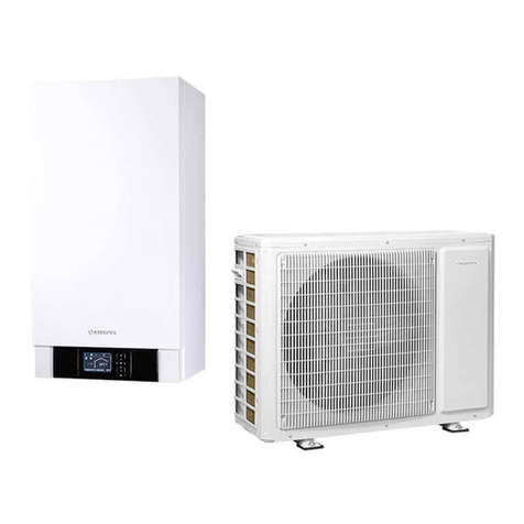
Heat pump HPM is a device used to heat/cool the building and heat the domestic hot
water.
Device is equipped with two units:
- outdoor unit HPMO, compressor heat pump.
Operation of the device is based on taking heat from the environment and forwarding
it to the heating circuit in the building. Low temperature air heat is transferred through
the evaporator into the heat pump system lled a refrigerant, which evaporated turns
to gas. The gas from the evaporator is sucked in by compressor, which raises its
temperature and transfers it when it is compressed to the condenser. In the condenser,
heat is transferred to the medium lling the central heating system, cooled liquid
ows through the expansion valve and goes back to the evaporator, whereupon the
whole process starts again. In the case of cooling, this cycle is reversed and heat is
extracted from the building and discharged outdoor.
- indoor HPMI unit with a built-in heating system controller.
The principle of operation of the device is based on the need-based regulation of
the capacity of the heat pump compressor with the switching of the electric heater
via the internal module controller. The indoor module control unit regulates the
rated power according to the set heating curve. If the heat pump is unable to cover
the building's heat demand on its own, the controller will automatically start the
additional electric heater which, together with the heat pump, produces the required
temperature of the heating medium.

4
Conditions for use and reliable operation of the device
1. Reading the contents of this instruction manual will enable proper installation and
operation of the device, ensuring its long-term and reliable operation.
2. The heat pump must be installed in accordance with the guidelines contained in
this user manual.
3. The HPM.P heat pump heating system consists of a set of optimally selected ele-
ments:
- HPMI indoor unit
- HPMO outdoor unit
- DHW cylinder SWPC
- SVK buffer tank
which guarantee the ecient and reliable operation of the HPM heat pump.
4. The manufacturer guarantees the correct operation and effective parameters of
the HPM heat pump only in cooperation with devices of the HPM.P.
5. The manufacturer is not responsible for the installation of the HPM heat pump with
other devices which may result in incorrect operation, lack of effective operating
parameters and increased operating costs of the heating system or a breakdown
of the HPM heat pump.
6. The manufacturer is not responsible for an incorrectly selected device to the heating
needs of the installation.

5
EN-102B_f.1296
1
1
2
2
3
3
4
4
5
5
6
6
7
7
8
8
9
9
10
10
12
12
14
14
15
15
16
16
17
17
18
18
11
11
13
13
[1] - ventilator
[2] - reversing valve
[3] - pressure switch
[4] - electromagnetic valve
[5] - compressor
[6] - liquid tank
[7] - service valve
[8] - heating medium inlet G1"
[9] - expansion valve
[10] - economizer
[11] - pressure transducer
[12] - heating medium outlet G1"
[13] - connection strip (PNL, modbus)
[14] - air vent socket (cork G1/2")
[15] - condenser
[16] - manometer
[17] - compressor controller
[18] - evaporator
Fig.1 Module HPMO

6
Fig. 2 Module HPMI
4
4
1
1
3
3
6
6
7
7
9
9
10
10
11
11
12
12
13
13
8
8
2
2
5
5
[1] - electrical connection
[2] - thermal cut-off
[3] - expansion vessel
[4] - automatic air vent
[5] - rated power
[6] - heating element
[7] - cooling circuit valve
[8] - safety valve
[9] - circulation pump
[10] - CH valve
[11] - DHW valve
[12] - control panel
[13] - device driver

7
EN-102B_f.1296
Heating and DHW mode with the heat pump switched off
When the outdoor temperature drops below the set shut-down temperature value,
the heat pump is automatically turned off and cannot produce heating water. In this
case, the heating and DHW mode is automatically performed by the additional electric
heater of the indoor unit.
Automatic defrost
Defrosting of the evaporator surface is done by reversing the refrigerant's circulation.
During the defrosting process the compressed gas is discharged from the compressor
to the evaporator, which melts the existing frost. The heating system cools down
slightly during this time. Duration the defrosting process depends on the degree of
frosting and the current external temperature. Active defrosting process is signaled
on the control panel by the icon .
Transport and storage
The HPMO heat pump should be transported and stored in a horizontal position.
Assembly
The heat pump is designed for outdoor installation and connection to indoor hydraulic
module with integrated additional electric heater. The device must be placed on a solid,
level base or foundation concrete. For fastening, use the attached vibration isolators.
To protect the device against snow and excessive moisture, base or the foundation
should protrude around 300mm above the ground level.
Prepare the ground under the foundation for free drainage of the condensate from
the drip tray. Drainage should be below the freezing zone. The layer thickness and
level must comply with local requirements and principles of construction technique.
The hole diameter should not be less than 100mm.
Condensate drain pipe should be thermally insulated. Thorough leveling the HPMO
outdoor unit will allow for free drainage of the condensate from the drip tray.
The heat pump should not be placed against the wall of rooms where noise could
interfere; e.g. by the bedroom wall. In order to maintain the high eciency of device it
is necessary to keep minimum distance against building's walls and other obstacles.
Restriction of the air ow can lead to the intake of cooled (heated in cooling mode)
air and lead to an increase in energy consumption of the compressor.
Connect the heating medium pipes to the heat pump and hydraulic module.

8
Noise
Sound pressure level for different distances from the device.
Power level
acoustic
Lw [dB (A)]
Directivity
factor
Q
Distance from the noise source r [m]
1 2 3 4 5 6 8 10 12 15
Sound pressure level Lp [dB (A)]
64
2 56 50 46 44 42 40 38 36 34 32
4 59 53 49 47 45 43 41 39 37 36
8 62 56 52 50 48 46 44 42 40 39
Q=2
Q=4
Q=8
Q = 2: freestanding heat pump on
the outside of the building.
Q = 4: heat pump on the building's wall.
Q = 8: heat pump on the building's wall
situated in the corner

9
EN-102B_f.1296
[1] - concrete foundation
[2] - gravel
[3] - the pipe for the condensate
[4] - gravel ground
[5] - base
[6] - vibration isolator
3
3
1
1
2
2
4
4
5
5
6
6
Fig.3 The assembly of outdoor unit HPMO
≥50cm
air inlet
air outlet
Proposed distance from right, left, top and behind wall - 50cm, front - 3m

10
Fig.4 The assembly of indoor unit HPMI
500 min.
300min.
300min.
47
47
34039
320
97
Ø50
49
418
751
617
7575 317
Ø35
Ø35
Ø35
4x dowel holes
expansion bolts
with a head
hexagonal
cable entry on
the left side
cover
cable entry
on the back
cover
480
50
location of the condensate drain socket
mounting screw spacing
649
330
12
354
874
36
1003
refrigerant manometer
heating medium
outlet G1"
air vent connection
electrical connection point
heating medium inlet G1"
109
603
65
709
Fig.4a The assembly of outdoor unit HPMO

11
EN-102B_f.1296
53
196
292
40
181
55.8 108 158.3 49
G3/4" drainage of
safety valve
CH buffer supplyG1" DHW supply
G1" outdoor unit
return (HPMO)
G1" circuit
cooling supply

12
Connection to the electric installation
Fig.5 Outdoor unit HPMO connection
Fig.6 Indoor unit HPMI connection
PCRK
PCRK
PO
PO
PG
PG
M
M
PM
ZM
ZM
TBCH
TBCH
TZM
TZM
TCRK
TCRK
TZAS
TZAS
TPOK
TPOK
TZEW
TZEW
RS485
RS485
RS485
RS485
FN2
FN2
FN1
FN1
C.MI2
C.MI2
HPMO
HPMO
L NA B
communication cable connection
power cord connection
PCRK - circulation pump DHW
PO - Circulation pump CH1 (radiator circuit)
PG - Glycol pump
PM - Mixing valve pump
ZM - Mixing valve
TBCH - Buffer temperature sensor
TZM - Temperature sensor behind mixing valve
TCRK - DHW circulation temperature sensor
TZAS - DHW cylinder temperature sensor
TPOK - Room temperature sensor
TZEW - outside temperature sensor
C.MI (Slave) - Internet module C.MI
HPMO (Master) - outdoor unit of heat pump
FN1 - outdoor heating blocked CH
FN2 - outdoor forcing the demand for cooling

13
EN-102B_f.1296
PE
PE
N
N
L1
L1
L2
L2
L3
L3
PE
PE
N
N
L3
L3
L2
L2
L1
L1
PE
PE
N
N
U
U
V
V
W
W
HPMO
L
L
N
N
PE
PE
PE
PE
PE
PE
N
N
N
N
U
U
U
U
V
V
W
W
L
L
N
N
L
L
N
N
PE
PE
HPMI
Fig.7 Diagram of connection the heat pump to three-phase installation
Fig.8 Diagram of connection the heat pump to one-phase installation
PE
PE
N
N
L
L
PE
PE
N
N
L
L
PE
PE
N
N
U
U
L
L
N
N
PE
PE
PE
PE
PE
PE
N
N
N
N
U
U
U
U
V
V
W
W
L
L
N
N
L
L
N
N
PE
PE
HPMO
HPMI
conguration of microswitches
device driver [13]
conguration of microswitches
device driver [13]

14
Connection of outdoor sensors and devices
Circulation temperature sensors (TCRK)
The assembly of sensor was shown on the diagram of hydraulic installation. The
connection cable of the temperature sensor should be as short as possible, it should
not be placed in close proximity to the power cords and twisted around other cords.
Attention, the connection of the sensor is optional, in case of its absence,
circulation pump works continuously according to circulation schedule. If the
sensor is connected, the circulation pump also works according to schedule,
however until the temperature in the circuit is stabilized. The circulation
temperature is checked at certain intervals, if there is a need to raise the water
temperature, then the pump is turned on.
In the absence of a sensor, the pump works continuously, but with connected sensor,
the pump works when the temperature in the circulation circuit drops. System control
automatically detects the presence of the sensor and accordingly adjusts circulation
pump's control algorithm.
Cooling buffer temperature sensor (TBCH)
The sensor mounting location is shown on the diagram of the hydraulic installation with
cooling fan coil. The connection cable of the temperature sensor should be as short as
possible, it should not be placed it in close proximity to the power cords and twisted
around other cords. The sensor is required if the device is congured for cooperation
with fan coil [SERVICE / CONFIGURATION -> Conguration -> Cooling -> Type: Fan coil].
Temperature sensor in the surface heating circuit (TZM)
The sensor mounting location is shown on the diagram of the hydraulic installation.
Sensor is required, if CH2 circuit is active [SERVICE / CONFIGURATION -> Conguration
-> CH2 circuit -> circuit: Yes].
Buffer temperature sensor (TZAS)
Buffer temperature sensor should be placed in the tank's socket.
Room temperature sensor (TPOK)
The connection cable of the temperature sensor should be as short as possible, it should
not be placed in close proximity to the power cords and twisted around other cords.
At a minimum height of 150 cm.

15
EN-102B_f.1296
Outside temperature sensor (TZEW)
The sensor should be mounted in a shaded place, on the north or north-west siede of the
building's facade, away from windows and vents. The connection cable of the temperature
sensor should be as short as possible, it should not be placed in close proximity to the
power cords and twisted around other cords.
Function input 1 (FN1 input)
Opening the input causes the device heating to be blocked. The input is active in winter
mode.
Function input (FN2 input)
Forcing the cooling demand externally. The input is active in summer mode. A short
circuit causes the unit to run in cooling mode as per set parameters.
In order to protect the hydraulic system against condensation, an HP.HS.24 humidity
sensor / switch can be connected to the circuit.

16
Connection to the hydraulic installation
The HPM heat pump can operate in a closed hydraulic installation system (minimum
pressure of the heating medium is 0.6 bar).
Hydraulic installation should be made in accordance with applicable standards. Wires
connecting the heat pump to the indoor module should have an inside diameter of min.
25mm. In order to protect against the transmission of vibrations to the system, exible
hoses must be used to connect the heat pump. Attach the hose to condensate drain.
The heating medium pipes and the drain pipe should be thermally insulated. The outlet
of the drain hose should be placed below depth exposed to freezing.
In case of minus temperatures, do not switch off the device. This will protect the outdoor
unit condenser from damage. If there is a risk of interruptions in the supply of electricity,
the circuit must be separated from hydraulic module by means of an additional heat
exchanger and the heat pump's heating circuit should be lled with glycol.
A prerequisite for maintaining the warranty is the installation of a dirt separator xed
at the inlet to the device.
The hydraulic installation must be made in such a way that the internal HPMI unit can
operate in the heating circuit without external HPMO unit (according to the following
installation diagrams). In case of a failure of the HPMO outdoor unit this will ensure the
functioning of the heating system.

17
EN-102B_f.1296
TI
TI
TI
TTTT
M
NW co
ZA EA NW cwu
ZB
ZN
ZCWU
TZM
PM
OG
TZEW
HPMO
TPOK
ZCO
PHP
PO
ZW
PI
HPMI
OP
ZCH
ZM
KO
SZ
PCRK
CWU
SWPC
SVK
TZAS
HP.HS.24
TCRK
Fig.9 An examplary diagram of an installation with a plane heating circuit / cooling circuit,
radiator circuit, heating buffer and storage tank domestic hot water. .
Fig.10 An examplary diagram of an installation with a plane heating circuit, radiator circuit,
heating buffer, storage tank domestic hot water and cooling circuit with fan coil.
TI
TI
TI
TTTT
M
ZW
PI
SZ
HP.HS.24
TBCH
ZA EA NW cwu
ZB
TZAS
SVK
NW co
ZN
PCRK
SWPC
TCRK
CWU
PM PO
ZM
TZM
OG TPOK
OP
FC
ZCWU ZCO
PHP
HPMI
ZCH
TZEW
HPMO
KO

18
HPMO - heat pump (10kW A7/W35)
HPMI - hydraulic module (4/6/8kW)
KO - venting connection
SZ - dirt separator
TZEW - outside temperature sensor
ZCWU - zone valve, loading the domestic hot water cylinder
ZCO - zone valve, loading the buffer tank CH
ZCH - zone valve, circuit cooling supply
PHP - circulation pump
OG - radiator heating
TPOK - room temperature sensor
OP - plane heating
PM - plane heating circulation pump
TZM - circuit plane heating temperature sensor
ZM - mixing valve
SWPC - DHW cylinder
SVK - heating/cooling water buffer tank
TZAS - temperature sensor in the DHW cylinder (WE-019/01)
PCRK - DHW circulation pump
FC - fan coil
HP.HS.24 - humidity switch for 1 cooling circuit
CWU - domestic hot water
ZW - cold water inlety
ZA - EA class anti-contamination valve
ZB - safery valve
NWcwu - DHW expansion vessel
NWco - CH expansion vessel
PO - circulation pump
ZN - relief valve
TBCH - factor temperature sensor in the buffer
TCRK - water temperature sensor in the circulation circuit
Filling and venting
The heating medium system must be lled with water to the required pressure and vented.
The indoor module has an automatic air vent. Fig. 2 pos. 4, while the heat exchanger in
the outdoor unit can be vented by loosening the nut of the venting socket Fig. 1, pos.
14. Filling and relling water the heating circuit should be clean, without visible deposits
and correspond to the quality of water intended for consumption and the requirements
contained in VDI 2035.

19
EN-102B_f.1296
Maintenance
Regularly clean the surface of the evaporator from leaves, dust and others. Switch off the
device before cleaning. In order to disable the device, select the Stand-by mode with the
knob and disconnect electric power supply. The evaporator ns are made of aluminium
strips. Do not use hard objects or detergents to clean the evaporator ns containing
chlorine, acids or abrasives; use generally available preparations for cleaning evaporators
and condensers in air-conditioning and cooling installations. After cleaning, check the
condensate drain. While plentiful snowfall, snow can accumulate on the evaporator
and on the top cover of the heat pump. Snow must be cleared to avoid ice formation.
Necessary steps including zero commissioning are:
1. Start-up of the HP heating system and checking its operation (proper setting of
operating parameters and matching them to the properties of the thermal insulation
of the building, installation).
2. Conguration and setting of basic operating parameters (programming room
temperature and DHW).
3. Assessment of the assembly in terms of leaks, disturbing noises (e.g. noise at poor
deaeration).
4. Initial user instruction in the use of the HP system
5. Record the relevant parameters in the Start-up chart form in the HPM.Z operating
instruction.
6. Zero Commissioning registration by the installation company in the Aura Kospel
system, https://aura.kospel.pl/commission/createFromShortcut? shortcut_id = 27.

20
Activities to be performed at the Zero Commissioning:
Electrical system condition control
• Measurement of the supply voltage of the HPMI indoor unit - _ _ _ V.
• Checking the correctness of the installed electric wires in the internal HPMI unit
(tightening the electric wires).
Assessment of tightness of the hydraulic system
• Reading the pressure of the heating medium on the control panel of the indoor
HPMI unit- _ _ _bar.
Cleaning the dirt separator
• Checking the pressure in the expansion vessel of the HPMI indoor unit - _ _ _bar.
• Reading the flow value in the heating circuit during operation - _ _ _ l min,
inlet _ _ _ °C, outlet _ _ _ °C.
Checking zone valves.
Cleaning the lters.
Checking the operation of zone valves.
HPMO outdoor unit refrigerant pressure check.
Evaluation of the technical condition and cleaning the evaporator.
Checking the drainage of the condensate.
Checking the correctness of the installed electric wires in the external HPMO unit
(tightening electric wires).
Assessment of the technical condition of the outdoor unit.
Table of contents
Other Kospel Heat Pump manuals
Popular Heat Pump manuals by other brands

American Standard
American Standard 4A6L5024N1000A Installer's guide

GE
GE AJHS08DCB Specifications

ICE AIR
ICE AIR CHPW installation manual

Metro Therm
Metro Therm METROAIR AQUA HPM manual

EAS Electric
EAS Electric EBP08WZR instruction manual

ThermoPlus Air
ThermoPlus Air KHPE Series Installation, operation and maintenance manual

Trianco
Trianco ActiveAir S1800 S User, installation, comissioning & servicing instructions

GE
GE Zoneline AZ85H18DAC datasheet

Smith
Smith HPW-60A user guide

Haier
Haier GE Connect Series Service manual

Daikin
Daikin VRV IV RXYLQ10T7Y1B Series Installation and operation manual

THERMAL ARK
THERMAL ARK ARK 270 Installation & operation