SolarEast BLN-006TB1 User manual

Service Manual
Heat Pump for Heating & Cooling & DHW
Service Manual
Model:
BLN-006TB1、BLN-006TD1
BLN-010TB1、BLN-010TB3
BLN-014TB1、BLN-014TB3
BLN-018TB1、BLN-018TB3
BLN-024TB3、BLN-024TD3
BLN-010TD1、BLN-010TD3
BLN-014TD1、BLN-014TD3
BLN-018TD1、BLN-018TD3
SolarEast Heat Pump Ltd.

SolarEast Heat Pump Ltd. 2212.A02
I
contents
1. Product introduction.....................................................................................................................1
1.1. Product model pictures......................................................................................................1
1.2. Parameter Table .................................................................................................................3
1.3. Dimension ..........................................................................................................................5
1.3.1. BLN-006TB1、BLN-010TB1、BLN-010TB3 .............................................................5
1.3.2. BLN-014TB1、BLN-014TB3.....................................................................................6
1.3.3. BLN-018TB1、BLN-018TB3、BLN-024TB3 .............................................................7
1.3.4. BLN-006TD1、BLN-010TD1、BLN-010TD3 ............................................................8
1.3.5. BLN-014TD1、BLN-014TD3 ....................................................................................9
1.3.6. BLN-018TB1、BLN-018TB3、BLN-024TB3 ...........................................................10
1.4. Exploded view ..................................................................................................................11
1.4.1. BLN-006TB1、BLN-010TB1、BLN-010TB3、BLN-014TB1、BLN-014TB3............11
1.4.2. BLN-006TD1、BLN-010TD1、BLN-010TD3、BLN-014TD1、BLN-014TD3 ..........12
1.4.3. BLN-018TB1、BLN-018TB3、BLN-024TB3 ...........................................................13
1.4.4. BLN-018TD1、BLN-018TD3、BLN-024TD3 ..........................................................14
1.5. System diagrams and performance curves ......................................................................15
1.5.1. Schematic diagram of the cooling system.............................................................15
1.5.2. How heat pumps work..........................................................................................16
1.5.3. Introduction to Heat Pump System Components .................................................17
1.5.4. Heating Performance Curve..................................................................................20
2. Product selection and installation...............................................................................................25
2.1. Product installation instructions and special precautions ...............................................25
2.1.1. Disclaimer..............................................................................................................25
2.1.2. warning..................................................................................................................26
2.1.3. Precautions............................................................................................................26
2.2. Installation........................................................................................................................27
2.2.1.Heat pump installation...........................................................................................27
2.2.2. Auxiliary pump installation....................................................................................28
2.3. Pipeline installation; water pressure commissioning; pipeline insulation requirements 29
2.3.1. Water distribution installation system diagram....................................................29
2.4. Precautions for electrical wiring.......................................................................................31
2.5. Room heat load calculation..............................................................................................34
2.5.1. basic requirements................................................................................................34
2.5.2. water system design..............................................................................................36
2.5.3. Distributor and water collector configuration principle........................................36
2.5.4. Selection of floor heating heat pump unit............................................................37
2.6. *Waterway antifreeze protection ....................................................................................47
3. Electrical operation .....................................................................................................................48
3.1. Control..............................................................................................................................48
3.1.1. out of service.........................................................................................................48
3.1.2. DC water pump control(PWM)........................................................................48
3.1.3. Start control ..........................................................................................................48

SolarEast Heat Pump Ltd. 2212.A02
II
3.1.4. High temperature sterilization ..............................................................................51
3.1.5. Silent mode .......................................................................................................51
3.1.6. Waterway emptying mode/forced open water pump ..........................................51
3.1.7. Forced defrost ................................................................................................51
3.1.8. Linkage control......................................................................................................52
3.1.9. Refrigerant recovery function ...............................................................................52
3.1.10. Expiry date password setting ..............................................................................52
3.1.11. Electric heating control EH1/gas control signal output.......................................52
3.1.12. Heating auxiliary electric heater EH2..................................................................53
3.1.13. Unit auxiliary pump P_c ......................................................................................54
3.1.14. Hot water three-way valve SV1...........................................................................54
3.1.15. Air conditioning three-way valve SV2 .................................................................54
3.1.16. Air conditioner secondary water pump P_b (secondary system) .......................55
3.1.17. Heat source hot water pump P_e .......................................................................55
3.1.18. Heat source heating water pump P_f .................................................................56
3.1.19. winter frost protection........................................................................................56
3.1.20. Host water flow switch protection......................................................................58
3.1.21. Protection against excessive temperature difference between inlet and outlet
pipes................................................................................................................................59
3.1.22. High voltage protection.......................................................................................59
3.1.23. Low voltage protection .......................................................................................59
3.1.24. Exhaust temperature too high protection...........................................................59
3.2. Display and operation of the wire controller ...................................................................60
3.2.1. Wire controller interface display and operation ...................................................60
3.2.2. Setting and operation of climate temperature curve............................................64
3.2.3. Setting and operation of unit tooling number ......................................................66
3.2.4. Network connection method and display of multiple units..................................67
.3.2.5. Operation method of unit status parameter query .............................................68
3.2.6. Factory parameter setting method .......................................................................70
3.2.7. Reset......................................................................................................................72
3.2.8. *Touch screen controller operation ......................................................................73
L parameter setting table................................................................................................88
P parameter setting table................................................................................................89
3.3. Setting method of pump flow range setting value...........................................................93
3.4. Outdoor unit electric control box layout..........................................................................94
3.4.1. BLN-006TB1/ BLN-010TB1/ BLN-014TB1/ BLN-018TB1........................................94
3.4.2. BLN-018TB1...........................................................................................................95
3.4.3. BLN-006TB1/ BLN-010TB1/ BLN-014TB1/ BLN-018TB1 ........................................95
3.4.4. BLN-010TB3/ BLN-014TB3.....................................................................................96
3.4.5. BLN-018TB3...........................................................................................................96
3.4.6. BLN-024TB3...........................................................................................................97
3.4.7. BLN-010TB3/ BLN-014TB3/ BLN-018TB3/ BLN-024TB3 ........................................97
3.5. Host unit port definition diagram ....................................................................................98

SolarEast Heat Pump Ltd. 2212.A02
III
3.5.1. Main control board port definition diagram (AP1) ...............................................98
3.5.2. Port Definition Diagram of Water Pump Expansion Board (AP3)..........................99
3.5.3. Port definition diagram of switching power supply (AP4)...................................101
3.5.4. DC fan board port definition diagram (AP5)........................................................101
3.5.5. Compressor driver board port definition diagram (AP4) ....................................101
3.6. Fault code and fault reason............................................................................................103
3.7. Waterway installation and wiring...................................................................................109
3.7.1. Comparison of system legends ...........................................................................109
3.7.2. Single floor heating mode water system installation diagram............................110
3.7.3. Heating or cooling mode water system installation diagram..............................110
3.7.4. Schematic diagram of wiring in floor heating, heating, and cooling modes.......111
3.7.5. Hot water + cooling or hot water + heating mode water system installation diagram
.......................................................................................................................................112
3.7.6. Hot water + floor heating mode water system installation diagram...................112
3.7.7. Water wiring diagram for hot water + cooling, hot water + heating, hot water +
floor heating modes......................................................................................................113
3.7.8. Mixed mode waterway system installation diagram...........................................114
3.7.9. Wiring diagram in hybrid mode ..........................................................................115
3.7.10. Cascade mode waterway installation schematic...............................................116
3.7.11. Cascading mode water circuit wiring diagram..................................................117
3.7.12. Floor heating + refrigeration + hot water + gas waterway installation schematic
.......................................................................................................................................118
3.7.13. Floor heating + refrigeration + hot water + gas water circuit wiring diagram...119
3.7.14. Three-way valve wiring method........................................................................120
3.8. Wiring diagram of each model.......................................................................................121
3.8.1. BLN-006TB1/ BLN-010TB1/ BLN-014TB1/ BLN-018TB1 electrical schematic
diagram .........................................................................................................................121
3.8.2. BLN-010TB3/ BLN-014TB3/ BLN-018TB3/ BLN-024TB3 electrical schematic
diagram .........................................................................................................................122
3.9. NCT Sensor Resistance Table..........................................................................................123
4. Error Diagnosis and Treatment .................................................................................................125
4.1. maintenance tools..........................................................................................................125
4.2. Model disassembly and parts ........................................................................................127
4.3. Troubleshooting and maintenance of common fault codes ..........................................143
Schedule........................................................................................................................................154
Schedule A: Unit Ground Heat Dissipation and Ground-to-Soil Heat Loss ...........................154
(1) Heat dissipation per unit ground area of PE-X pipe and heat loss when turning
downwards....................................................................................................................154
(2) Heat dissipation per unit ground area of PB pipe and heat loss when turning
downwards....................................................................................................................157
Schedule B: Coefficient of Expansion of Water.....................................................................160

SolarEast Heat Pump Ltd. 2212.A02
1
1. Product introduction
1.1. Product model pictures
Model
BLN-006TB1
BLN-010TB1、BLN-010TB3
BLN-014TB1、BLN-014TB3
BLN-006TB1
BLN-010TB1、BLN-010TB3
BLN-014TB1、BLN-014TB3
Picture
Model
BLN-018TB1、BLN-018TB3
BLN-024TB3
BLN-018TB1、BLN-018TB3
BLN-024TB3
Picture

SolarEast Heat Pump Ltd. 2212.A02
2
Model
BLN-006TD1
BLN-010TD1、BLN-010TD3
BLN-014TD1、BLN-014TD3
BLN-006TD1
BLN-010TD1、BLN-010TD3
BLN-014TD1、BLN-014TD3
Picture
Model
BLN-018TD1、BLN-018TD3
BLN-024TD3
Picture
Table 1-1
Note: TB and TD series are identical in unit capacity and electric control operation
except appearance. The following contents are as follows TB Series.

SolarEast Heat Pump Ltd. 2212.A02
3
1.2. Parameter Table
Model
BLN-006TB1
BLN-010TB1
BLN-010TB3
BLN-014TB1
BLN-014TB3
BLN-018TB1
BLN-018TB3
BLN-024TB3
Power Supply
220-240V
~/50Hz
220-240V
~/50Hz
380-
415V/3N~/50
Hz
220-240V
~/50Hz
380-
415V/3N~/50
Hz
220-240V
~/50Hz
380-
415V/3N~/50
Hz
380-
415V/3N~/50
Hz
Heating ¹
Capacity
KW
2.50-8.30
4.20-12.20
4.20-12.20
5.30-16.50
5.30-16.60
6.20-20.50
6.20-20.50
6.50-26.10
Input
Power
KW
0.57-1.92
0.86-2.88
0.86-2.88
1.15-4.15
1.15-4.15
1.36-5.28
1.36-5.28
1.78-6.45
Input
Current
A
2.53-8.52
3.82-12.77
1.46-4.89
5.10-18.41
1.86-6.70
6.10-23.67
2.31-8.96
2.87-10.35
Heating ²
Capacity
KW
2.30-7.62
3.85-11.20
3.85-11.20
4.90-15.10
4.90-15.10
6.30-19.90
6.30-19.90
6.90-26.10
Input
Power
KW
0.75-2.61
1.13-3.75
1.13-3.75
1.65-5.25
1.65-5.25
1.65-6.82
1.65-6.82
1.95-8.55
Input
Current
A
3.32-11.58
5.01-16.6
1.92-6.37
7.32-23.30
1.67-8.47
7.40-30.56
2.80-11.58
3.15-13.80
Cooling
Capacity
KW
1.80-7.10
2.60-10.30
2.60-10.30
4.50-13.50
4.50-13.50
5.50-17.50
5.50-17.50
5.20-21.30
Input
Power
KW
0.61-2.43
0.91-3.65
0.91-3.65
1.45-4.85
1.45-4.85
1.65-6.25
1.65-6.25
1.95-8.20
Input
Current
A
2.71-10.78
4.03-16.19
1.55-6.20
6.43-21.52
2.34-7.82
7.40-28.02
2.80-10.61
3.15-13.23
SCOP (Water Temp.
At 35℃)
5.14
4.55
4.55
4.58
4.62
4.61
4.64
4.58
SCOP (Water Temp.
At 55℃)
3.37
3.41
3.41
3.39
3.44
3.41
3.42
3.42
Rated Input Power
kW
2.71
3.83
3.83
6.2
6.2
7.5
7.5
10
Rated Input Current
A
12
17
6.5
27.5
10.50
35
13
17
Refrigerant
Type/Charge/GWP
...
/kg
R32/1.25/675
R32/1.8/675
R32/1.8/675
R32/2.8/675
R32/2.8/675
R32/3.5/675
R32/3.5/675
R32/3.5/675
CO₂ Equivalent
/
0.84t
1.21t
1.21t
1.89t
1.89t
2.36t
2.36t
2.36t
Operation
Pressure(Low Side)
MPa
1.5
1.5
1.5
1.5
1.5
1.5
1.5
1.5
Operation
Pressure(High Side)
MPa
4.4
4.4
4.4
4.4
4.4
4.4
4.4
4.4
Table 1-2
Rated Test Conditions:
Heating¹: Ambient Temp 7℃/6℃(DB/WB),Water-In/Out Temp 30℃/35℃
Heating²: Ambient Temp 7℃/6℃(DB/WB),Water-In/Out Temp 47℃/55℃
Cooling: Ambient Temp 35℃/24℃(DB/WB),Water-In/Out Temp 12℃/7℃

SolarEast Heat Pump Ltd. 2212.A02
4
Model
BLN-006TB1
BLN-010TB1
BLN-010TB3
BLN-014TB1
BLN-014TB3
BLN-018TB1
BLN-018TB3
BLN-024TB3
Maximum Allowable
Pressure
MPa
4.4
4.4
4.4
4.4
4.4
4.4
4.4
4.4
Electrical Shockproof
/
I
I
I
I
I
I
I
I
IP Class
/
IPX4
IPX4
IPX4
IPX4
IPX4
IPX4
IPX4
IPX4
Max. Outlet Water
Temp.
℃
60
60
60
60
60
60
60
60
Operating Ambient
Temperature
℃
-25~45
-25~45
-25~45
-25~45
-25~45
-25~45
-25~45
-25~45
Water Piping
Connections
inch
G1
G1
G1
G1-1/4
G1-1/4
G1-1/2
G1-1/2
G1-1/2
Rated Water Flow
m³/h
1.1
1.75
1.75
2.52
2.52
3.2
3.2
4.12
Water Pressure Drop
kPa
25
27
27
30
30
32
32
35
Min/Max water
pressure
MPa
0.1/0.3
0.1/0.3
0.1/0.3
0.1/0.3
0.1/0.3
0.1/0.3
0.1/0.3
0.1/0.3
Noise Level
dB(A)
50
51
51
55
55
56
56
58
Net Dimensions
( L×W×H )
mm
1100×445×850
1110×480×850
1110×445×1450
Pack Dimensions
( L×W×H )
mm
1160×530×1010
1160×565×1010
1170×530×1610
Net Weight
kg
102
107
107
124
124
151
151
160
Gross Weight
kg
114
119
119
136
136
168
168
177
Table 1-3
Note: Parameters are subject to change without prior notice. Please refer to the unit
nameplate.
SolarEast Heat Pump Ltd. 2212.A02
5
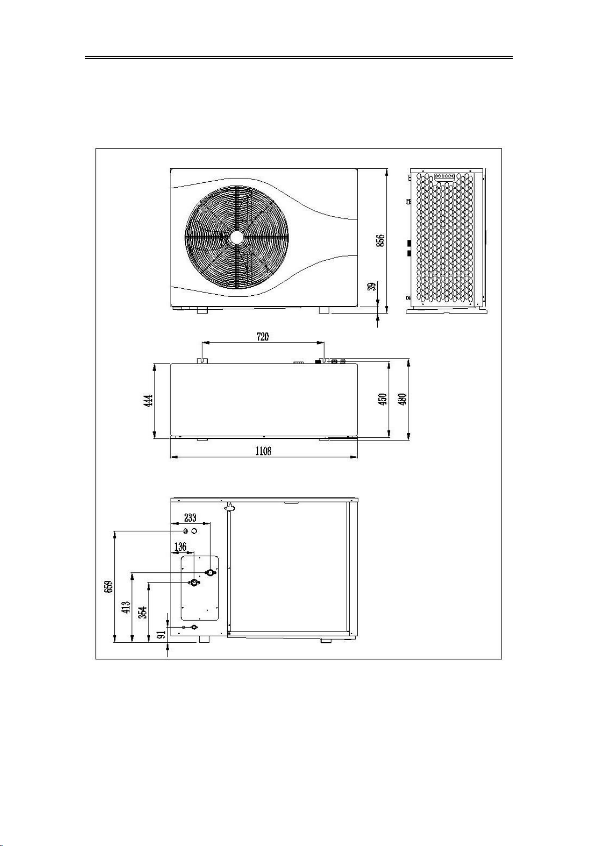
1.3. Dimension
1.3.1. BLN-006TB1、BLN-010TB1、BLN-010TB3
Figure 1-1

SolarEast Heat Pump Ltd. 2212.A02
6
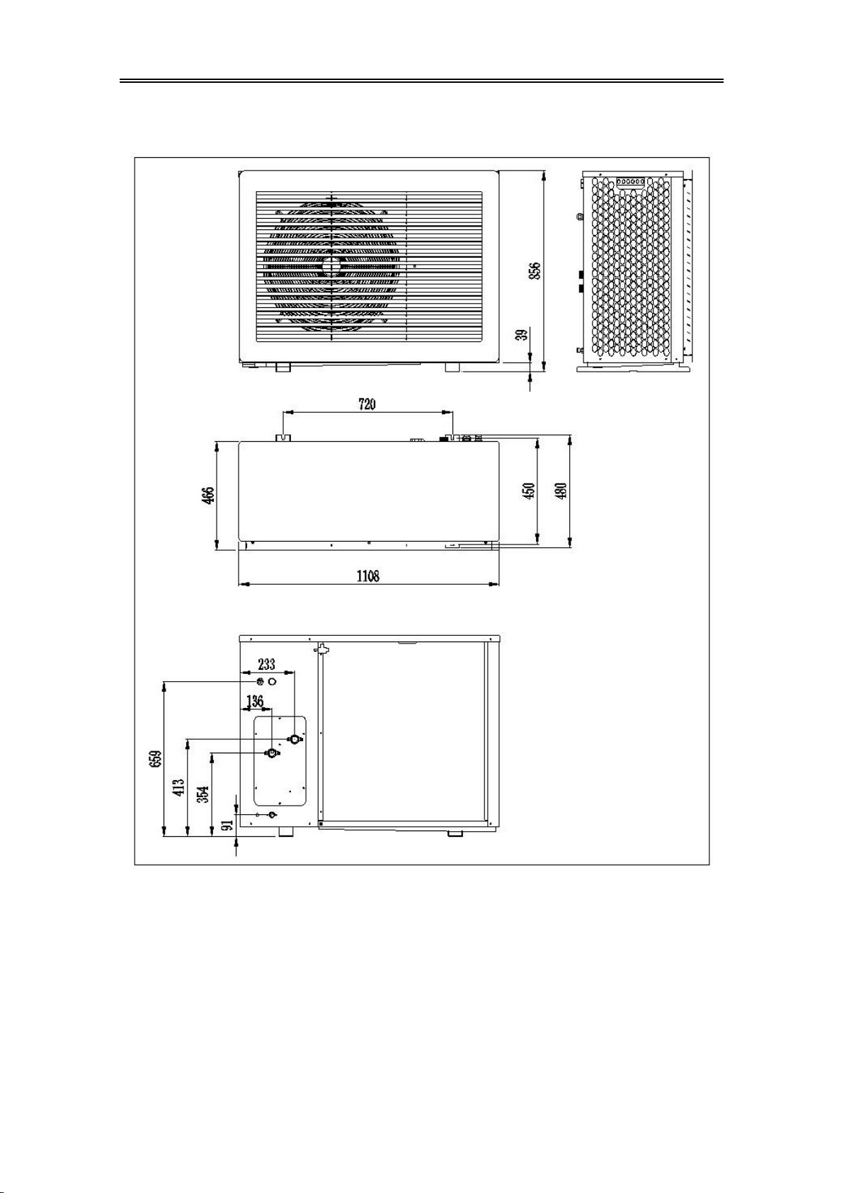
1.3.2. BLN-014TB1、BLN-014TB3
Figure 1-2

SolarEast Heat Pump Ltd. 2212.A02
7
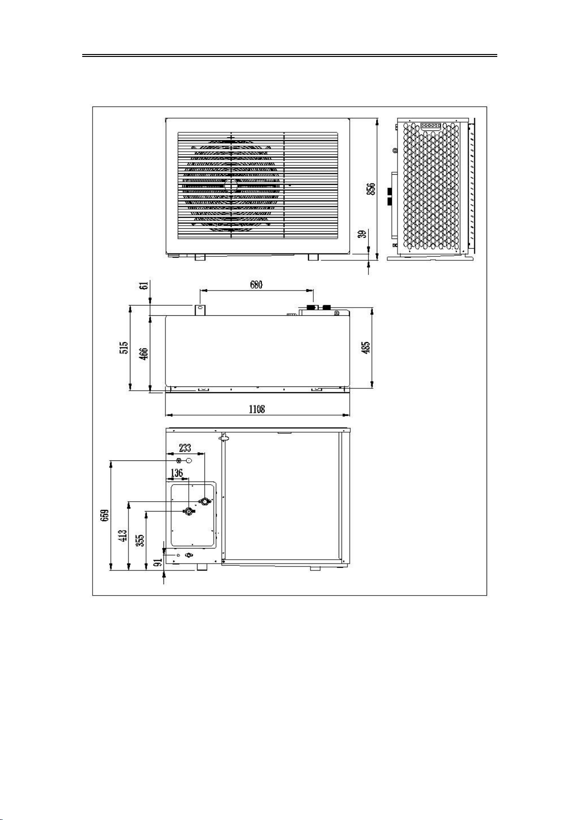
1.3.3. BLN-018TB1、BLN-018TB3、BLN-024TB3
Figure 1-3
SolarEast Heat Pump Ltd. 2212.A02
8
1.3.4. BLN-006TD1、BLN-010TD1、BLN-010TD3
Figure 1-4
SolarEast Heat Pump Ltd. 2212.A02
9
1.3.5. BLN-014TD1、BLN-014TD3
Figure 1-5

SolarEast Heat Pump Ltd. 2212.A02
10
1.3.6. BLN-018TB1、BLN-018TB3、BLN-024TB3
Figure 1-6

SolarEast Heat Pump Ltd. 2212.A02
11
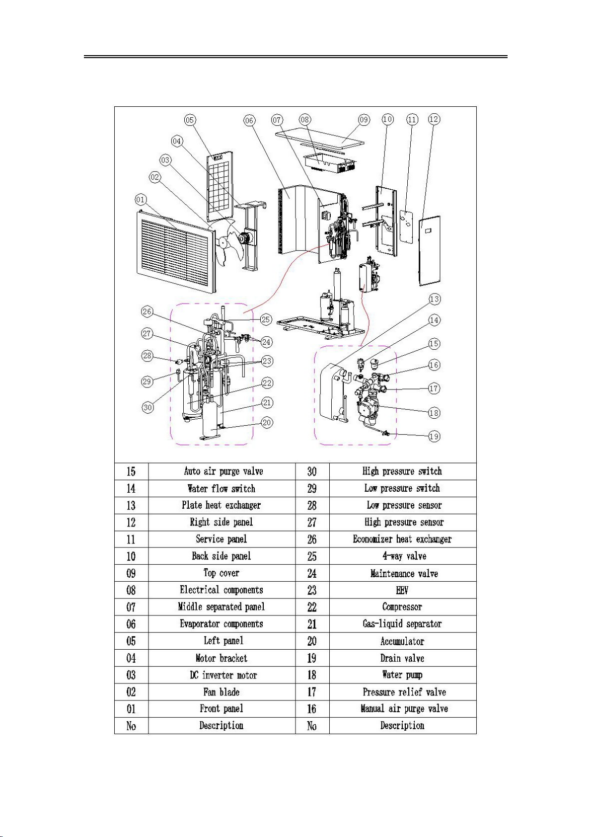
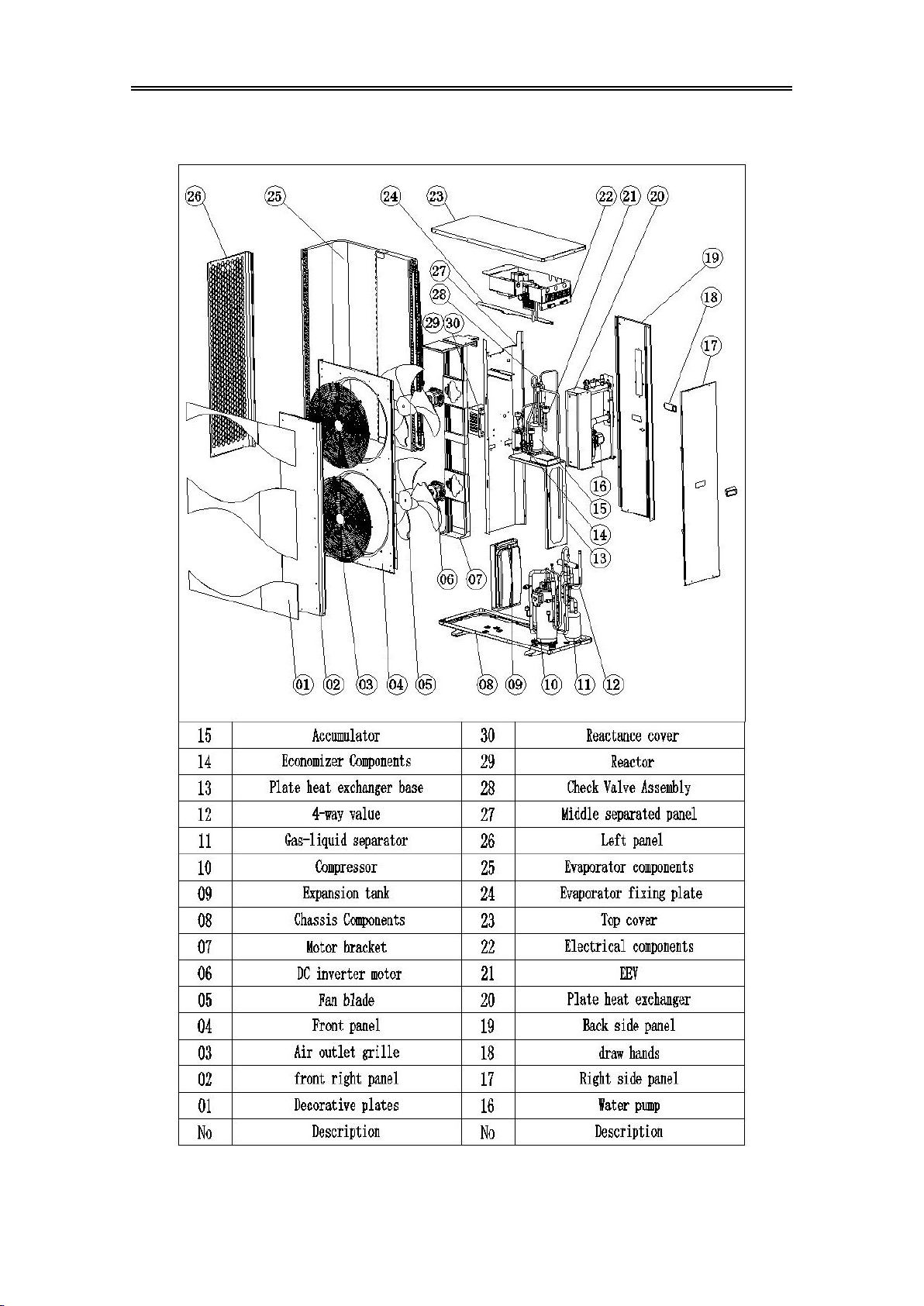
1.4. Exploded view
1.4.1. BLN-006TB1、BLN-010TB1、BLN-010TB3、BLN-014TB1、BLN-014TB3
Figure 1-7
SolarEast Heat Pump Ltd. 2212.A02
12
1.4.2. BLN-006TD1、BLN-010TD1、BLN-010TD3、BLN-014TD1、BLN-014TD3
Figure 1-8
SolarEast Heat Pump Ltd. 2212.A02
13
1.4.3. BLN-018TB1、BLN-018TB3、BLN-024TB3
Figure 1-9

SolarEast Heat Pump Ltd. 2212.A02
14
1.4.4. BLN-018TD1、BLN-018TD3、BLN-024TD3
Figure 1-10
SolarEast Heat Pump Ltd. 2212.A02
15
1.5. System diagrams and performance curves
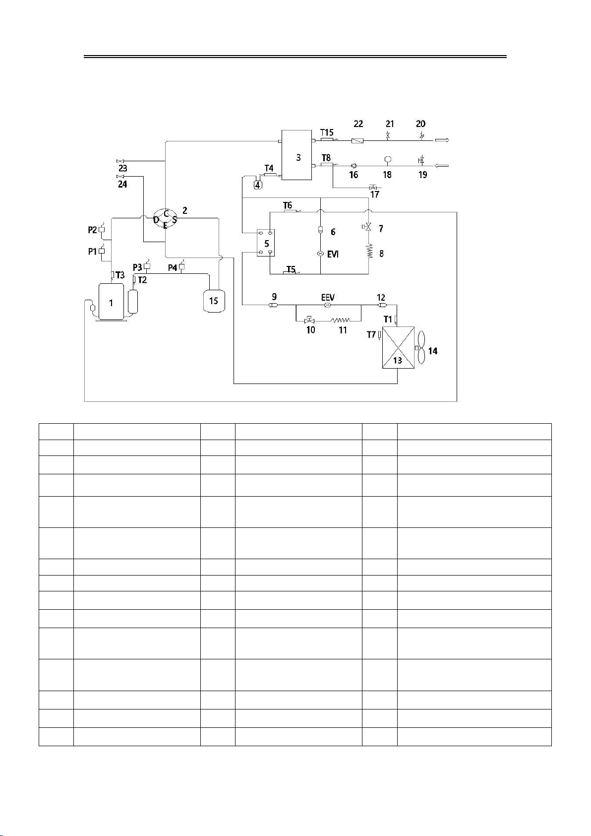
1.5.1. Schematic diagram of the cooling system
Figure 1-11
code
Description
code
Description
code
Description
1
Compressors
15
Gas-liquid separators
T5
Economiser inlet temperature sensor
2
Four-way directional valves
16
DC circulation pumps
T6
Economiser outlet temperature sensor
3
Plate heat exchangers
17
Manual drain valve
T7
Ambient temperature sensor
4
Liquid reservoirs
18*
Expansion tank
(not standard)
T8
Inlet temperature sensor
5
Economiser
19*
Manual exhaust valve
(not standard)
T15
Discharge temperature sensor
6
Filter 1
20
Safety valve
P1
High pressure sensors
7
Liquid injection solenoid valve
21
Automatic air venting valve
P2
High pressure switch
8
Liquid injection capillary tube
22
Water flow switch
P3
Low pressure sensors
9
Filter 2
23
High pressure service valve
P4
Low pressure switch
10*
Throttle solenoid valve
(not standard)
24
Low pressure service valve
EEV
Main electronic expansion valve
11*
Auxiliary throttle capillary
(not standard)
T1
Coil temperature sensors
EVI
Auxiliary electronic expansion valve
12
Filter 3
T2
Suction temperature sensor
13
Finned exchanger
T3
Exhaust air temperature sensor
14
Fans
T4
Inner coil temperature sensor
Table 1-4
SolarEast Heat Pump Ltd. 2212.A02
16
Non-standard parts for each model
Table 1-5
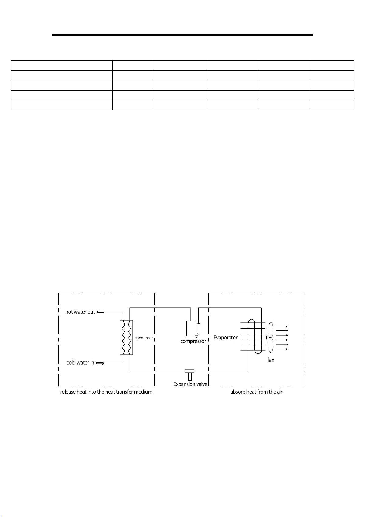
1.5.2. How heat pumps work
The heat pump system is mainly composed of four major components:
compressor, condenser, throttling device and evaporator. Its working principle is to
use electric energy to drive the compressor to compress the low-temperature and
low-pressure gaseous refrigerant into high-temperature and high-pressure steam,
then condense and dissipate heat in the condenser (plate heat exchanger), and release
the heat to the heat transfer medium (water ), the heat source is provided to the user
through the heat transfer medium (water) for heating or domestic hot water; the
condensed medium-temperature and high-pressure refrigerant becomes a low-
temperature and low-pressure liquid after being throttled by the throttling device,
and then passes through the evaporator (fin Plate heat exchanger) absorbs heat into
the air environment and vaporizes to form a low-temperature and low-pressure gas,
which enters the compressor again to be compressed, thus forming a repeated cycle.
Working principle diagram:
Figure 1-12
Machine type
BLN-006TB1
BLN-010TB1/B3
BLN-014TB1/B3
BLN-018TB1/B3
BLN-024TB3
10 Throttle solenoid
√
×
×
×
×
11 Auxiliary throttling capillary tube
×
×
×
×
√
18 Expansion tank
×
×
×
√
√
19 Manual exhaust valve
√
√
√
×
×
Other manuals for BLN-006TB1
1
This manual suits for next models
15
Table of contents
Other SolarEast Heat Pump manuals

Popular Heat Pump manuals by other brands


Daikin
Daikin Altherma EKCBH-BAV3 installation manual

Midea
Midea V4 Plus S Series Technical & service manual

EVEREST REFRIGERATION
EVEREST REFRIGERATION ETBR1 owner's manual

Brilix
Brilix XHPFD 80 E user manual

Mitsubishi Electric
Mitsubishi Electric PUHZ-W50VHA Service manual

Whirlpool
Whirlpool GOLD W4GH6 installation instructions


