Kowa nonmyd 8 User manual

nonmyd 8 GG-15010 Edition 1.1
Edition 1.1
2016.11
Model Name:
K9L61 (D5300 model)

nonmyd 8 GG-15010 Edition 1.1
-1-
Contents
1. Name of each component ・・・・・・・・・・・・・・・・・・・・・・・・・・・・・・・・・・・・・・・・・ 2
2. Monitor Screen Indications ・・・・・・・・・・・・・・・・・・・・・・・・・・・・・・・・・・・・・・・・ 7
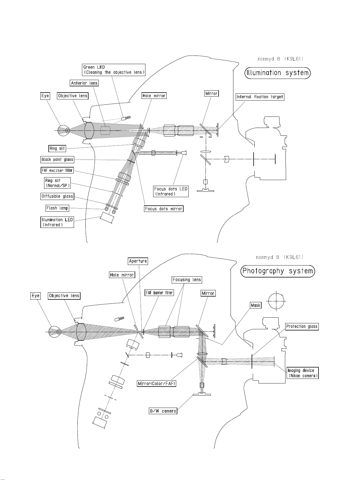
3. Optical pathways・・・・・・・・・・・・・・・・・・・・・・・・・・・・・・・・・・・・・・・・・・・・・・・・・ 9
4. Wiring Diagram ・・・・・・・・・・・・・・・・・・・・・・・・・・・・・・・・・・・・・・・・・・・・・・・・・ 10
5. Preparing for Part Replacement
5-1 Removing outer cover ・・・・・・・・・・・・・・・・・・・・・・・・・・・・・・・・・・・・・・・ 11
5-2 Removing the power supply cover・・・・・・・・・・・・・・・・・・・・・・・・・・・・・ 15
5-3 Removing the optical head base ・・・・・・・・・・・・・・・・・・・・・・・・・・・・・・ 18
5-4 Configuration of electrical component・・・・・・・・・・・・・・・・・・・・・・・・・・ 19
6. Replacing parts
6-1 The main body relation ・・・・・・・・・・・・・・・・・・・・・・・・・・・・・・・・・・・・・・ 20
6-2 The optical head base relation ・・・・・・・・・・・・・・・・・・・・・・・・・・・・・・・・ 22
6-3 Power supply relation・・・・・・・・・・・・・・・・・・・・・・・・・・・・・・・・・・・・・・・・・ 23
7. Lens cleaning
7-1 Preparing for lens cleaning ・・・・・・・・・・・・・・・・・・・・・・・・・・・・・・・・・・・ 24
7-2 Lens cleaning procedures ・・・・・・・・・・・・・・・・・・・・・・・・・・・・・・・・・・・・ 25
7-3 Lens cleaning part and cleaning method ・・・・・・・・・・・・・・・・・・・・・・・ 26
7-4 Cleaning of objective lens ・・・・・・・・・・・・・・・・・・・・・・・・・・・・・・・・・・・・ 27
8. Digital camera setting ・・・・・・・・・・・・・・・・・・・・・・・・・・・・・・・・・・・・・・・・・・・・・ 28
9. Troubleshooting
9-1 Abnormality concerning operation ・・・・・・・・・・・・・・・・・・・・・・・・・・・・・ 31
9-2 Abnormality concerning display ・・・・・・・・・・・・・・・・・・・・・・・・・・・・・・・ 33
9-3 Abnormality concerning photography or image ・・・・・・・・・・・・・・・・・・ 34
How to clean up the low-pass filter for Nikon D5300・・・・・・・・・・・・・・・・・・・・・・・・ 36
How to clean up the right and left detection sensor ・・・・・・・・・・・・・・・・・・・・・・・・ 38
How to adjust the black point glass・・・・・・・・・・・・・・・・・・・・・・・・・・・・・・・・・・・・・・・ 40

nonmyd 8 GG-15010 Edition 1.1
-2-
1. Name of each component

nonmyd 8 GG-15010 Edition 1.1
3

nonmyd 8 GG-15010 Edition 1.1
4

nonmyd 8 GG-15010 Edition 1.1
5

nonmyd 8 GG-15010 Edition 1.1
6

nonmyd 8 GG-15010 Edition 1.1
7
2. Monitor Screen Indications

nonmyd 8 GG-15010 Edition 1.1
8

nonmyd 8 GG-15010 Edition 1.1
3. Optical pathways

nonmyd 8 GG-15010 Edition 1.1
10
4. Wiring Diagram

nonmyd 8 GG-15010 Edition 1.1
11
5. Preparing for Part Replacement
5-1 Removing outer cover
*Always turn off the power switch before removing the outer cover.
●Optical head cover
〔Tools〕
・Flat-head screwdriver(Precision)
・Phillips screwdriver (No.2) Axis length 50mm or more
・Flat-head screwdriver
・Phillips screwdriver (No.2) Stubby type
〔Procedure〕
1 Remove the caps of both left and right focus knobs
with a flat-head screwdriver(Precision).
2 Loosen screws to remove the focus knobs,
while holding them with your hands to avoid its turning.
3 Loosen the screws of flash-lamp cover for its removal
with a flat-head screwdriver.
4 Remove the connectors plugged into a digital camera.
5 Keep pushing the lens removal button on a digital camera,
turn a digital camera clockwise and remove it.
6 Remove a long screw located above the flash lamp unit.

nonmyd 8 GG-15010 Edition 1.1
12
7 Remove two screws with phillips screwdriver
(No.2) Stubby type.
Remove the front cover.
8 Remove four screws with phillips screwdriver
(No.2).
Remove the top cover.
(No.2)
9 Remove two screws with phillips screwdriver.
Remove the right and left cover
from the optical head.
9
8

nonmyd 8 GG-15010 Edition 1.1
13
●Optical head base cover and panel cover
〔Tools〕
・Nipper
・Hex-wrench(2.5)
〔Procedure〕
1Remove five screws with hex-wrench(2.5).
Remove one of the optical head base covers.
And then remove another optical head base cover.
2Disconnect the cable connector from main board, sub board(three places).
C
ut a band,which holds the
cables,by using nippe .
(main boa d side)
<Caution fo esto ing>
Neve hold the yellow/g een
g ound wi e.
The e may be a isk of wi e
disconnection when some load is
applied to the g ound wi e
te minal.
Cut a band,
which holds the
cables,by using nippe .
Disconnect two
cable
connecto s.
(main boa d)

nonmyd 8 GG-15010 Edition 1.1
14
3Raise and extract a panel cover.
And disconnect a cable connector from joystick.
※Be careful not to damage joystick..
Disconnect a cable connecto
.
(sub boa d side)
Disconnect a
cable connecto .

nonmyd 8 GG-15010 Edition 1.1
15
5-2 Removing the power supply cover
*Always turn off the power switch and pull the plug from the socket.
〔Tools〕
・Phillips screwdriver (No.2)
・Nipper
〔Procedure〕
1 Remove the outer cover beforehand.(See 5-1)
2 Remove the optical head base fixing screw
with phillips screwdriver(No.2).
3 Tighten the lock screw.
4 Cut a band (side of shield-box) with nipper.
Remove four screws on shield-box with phillips screwdriver(No.2).
Remove shield-box.

nonmyd 8 GG-15010 Edition 1.1
16
5 Disconnect the cable connector connected to a power supply part from a sub board and a main
board..
6 Put the cushion on the left side of the main body
(view of the checker).
Cut a band
which
holds came a
cable and body.
Cut a band
which
holds came a
cable.
Disconnect g ound
wi e te minals.
D
isconnect two
cable connecto s.
(main boa d)
Disconnect
te minals.
Disconnect a cable
connecto .
Cut a band
.
Disconnect
a
clamp
Disconnect
two cable
connecto s.
(sub boa d)
Cut a band
.
Disconnect g ound
wi e te minals.
Disconnect a clamp
Disconnect a cable
connecto .

nonmyd 8 GG-15010 Edition 1.1
17
7 Lay the optical head base on cushion.
8 Removing the power supply,
and put it on the right side of the main body.

nonmyd 8 GG-15010 Edition 1.1
18
5-3 Removing the optical head base
*Always turn off the power switch and pull the plug from the socket.
〔Tools〕
・Phillips screwdriver (No.2)
・Nipper
〔Procedure〕
1 Remove the outer cover beforehand. (See 5-1)
2 Remove the power supply cover. (See 5-2)
3 Remove ten screws.
Remove the insertion prevention board.
Raise and extract a panel cover.
4 Remove two screws.
Remove the stoppers(left and right).
5 Loosen the the lock screw.
6 Raise the optical head base.
And put it next to the power supply cover.
※Note that rack and pinion is kept to be
horizontal when returning optical head base
to the original position.
4
4
5
6

nonmyd 8 GG-15010 Edition 1.1
19
5-4 Configuration of electrical component
【Optical component】
【power supply unit】
【Operation panel】
Capacitor H U
K9L61#7130H
Trans H
*HC-K9L57-5440
HV PCB
K9L61 #6230
SW power supply
MUZP-150-12-J0E
Interface PCB
K9L61 #5850
Main PCB
K9L61 #5150
SUB PCB
K9L61 #5160
Discharge PCB
K9L61 #7055A
Internal fixation U
K9L57 #5240
Left side
Right side
FD LED PCB
K9L57 #5050H
LCD U
K9L61 #6180
SW R1 PCB U
K9L57 #7130A
SW C PCB
K9L57 #7133A
Lamp VR&Flash SW
K9L61
-
7210H
SW L1 PCB U
K9L58 #7132A
Other manuals for nonmyd 8
1
This manual suits for next models
2
Table of contents
Other Kowa Digital Camera manuals
Popular Digital Camera manuals by other brands

FujiFilm
FujiFilm X20 owner's manual

Panasonic
Panasonic Lumix DMC-FH27 Basic operating instructions

lynx System Developers
lynx System Developers IdentiLynx SR quick start guide

Canon
Canon AE-1 instructions

miniland
miniland digital camera 5" Guarantee card and Instructions' Manual

Stealth Cam
Stealth Cam STC-CRV20 user manual