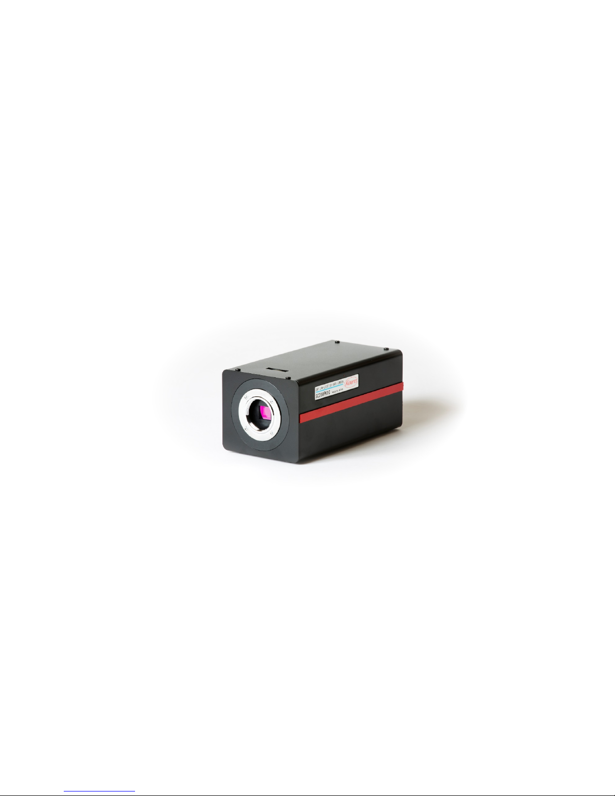
Kowa SC200PK1C User manual

Ultra High Sensitivity Color Camera
SC200PK1C
Operation Manual
Ver. 04.17.14
Kowa Optical Products Co., Ltd.

1.Names and Functions of Parts

No. Name Function
(1) Lens Mount (CS-Mount) Part where lens is connected to the camera. The camera
supports a wide variety of CS-mount lenses.
(2) Flange Focus Adjuster Used to adjust the flange focus (the distance from the
lens mounted surface to the image area).
(3) Flange Focus Fixing Screw Loosen this screw when maintain and adjusting the
camera flange focus. When the adjustment is finished,
retighten it.
(4) Auto Iris Connector Used to connect an auto-iris lens. It supports only DC
iris lenses.
(5) Tripod Screw Used to secure the camera to a tripod or the like. Use
only a 1/4-20UNC screw not longer than 5.5 mm.
(6) Fixing Hole Used to keep the camera from rotating.
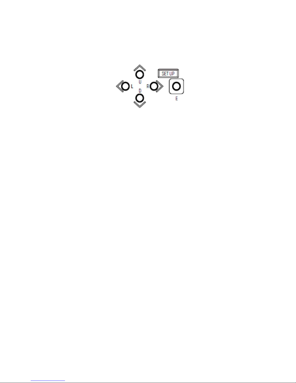
(7) Setup Button ←Used to change settings (←).
(8) Setup button ↑Used to select a setting item (↑).
(9) Setup button ↓Used to select a setting item (↓).
(10) Setup button →Used to change settings (→).
(11) Menu button Used to enter/exit the setup mode and determine/execute
settings.
(12) RS-485/day and night
switching terminal
Used to connect an RS-485 device to remotely switch
day and night modes.
(13) RS-485 terminator switch When RS-485 communication is used, set the switch to
the ON position to make a one-to-one connection or to
the OFF position to make a daisy chain connection (to
the ON position for only the last connected camera).
(14) 12 VDC terminal Used to input 12 VDC power. Pay attention to the
polarities.
(15) Power indicator A green LED stays illuminated when power is supplied
to the camera.
(16) HD-SDI output terminal Used to output HD-SDI images.
(17) SD output terminal Used to output analog SD VIDEO signals.
(18) GENLOCK IN
Used to input external synchronizing signals. For
external synchronization, input VBS, BBS, and VS
signals.
(19) GENLOCK IN TERM When external synchronization is used and a T
connector is used for looping, this must be set to OFF. In
normal cases, it must be set to ON.
(20) RESET button Used to reset the camera to the state when the camera
power is turned on.

2. Operating the Camera
2-1. Setting up the Camera
You can set up your camera using the OSD display and the buttons on the rear panel. You use the five
pushbuttons on the back of the camera.
Hold down the menu button for longer than 2 seconds to display the main menu. Through this menu, you
can set up camera functions. You can select any of the blinking items. To move to the next page, select
PAGE and press the R button. To go back to the previous page, press the L button.
2-1-1. SENSE UP Setting
(1) If this is not set to OFF or MANUAL, GAIN is automatically set to AGC. Alternatively, you can set
the gain to HYP-AGC.
(i) OFF
The electronic sensitivity enhancement does not function.
(ii) S/N
This option places the camera in the S/N priority mode. It is used to shoot a subject that is not
moving quickly.
The GAIN value increases to up to + 15 dB for AGC or up to + 21 dB for HYP-AGC.
(iii) STD
This option is used when you want to minimize blurring and grain in images.
The GAIN value increases to up to + 36 dB for AGC or up to + 42 dB for HYP-AGC.
(iv) MOVE
This option places the camera in the motion priority mode.
The GAIN value increases to up to + 54 dB for AGC or up to + 72 dB for HYP-AGC.
(v) MANUAL
This option fixes the magnification. You can change the magnification through the SHUTTER
settings.
(2) When one of the above options is selected, press the E button. This allows you to configure the
DAY/NIGHT setting and enable or disable the flicker-less function.
* When SENSE UP is set to OFF, you cannot configure the flicker-less setting. To configure the
flicker-less setting, select 1/100 through the SHUTTER settings.

(3) DAY/NIGHT Setting
(i) COLOR
The camera always outputs color video signals (with IR cutoff).
(ii) B/W
The camera always outputs monochrome video signals (with no IR cutoff).
(iii) AUTO
The camera automatically switches the mode to output high-quality video during the daytime and
high-sensitivity monochrome video during the nighttime.
In AUTO mode, the GAIN setting is configured to either AGC or HYP-AGC.
If this mode is selected, you can press the E button to configure the SWITCH LEVEL (switchover
brightness level) setting as follows:
LEVEL setting: You can set the switchover brightness level.
DARK: The switchover brightness level is low.
MID: The switchover brightness level is between DARK and BRIGHT.
BRIGHT: The switchover brightness level is high.
MANUAL: You can manually set switchover brightness level.
MANUAL setting: When the LEVEL setting is configured to MANUAL, you can configure the
following settings:
COLOR →B/W: You can set the brightness at which the mode changes from DAY to
Night.
B/W →COLOR: You can set the brightness at which the mode changes from Night to
DAY.
(iv) REMOTE
You can switch the DAY/NIGHT mode by external operation. You can configure the B/W COLOR
setting by configuring (12) RS-485/day and night switching terminal 1-2 shown in Names and
Functions of Parts to Short or Open. Depending on the MAIN MENU (PAGE4/5) IR TRIG.POL setting,
the short and open statuses change as follows:
RS485 control / day and night switching
terminal 1-2
Short Open
IR TRIG POL BRAKE COLOR B&W
MAKE B&W COLOR
(4) FLICKER-LESS
(i) OFF This option should be selected in normal cases.
(ii) ON When flicker is annoying under fluorescent light, select this option to fix the SHUTTER
setting to 1/100.
2-1-2. SHUTTER Setting
(1) When the SENSEUP setting is configured to OFF, the SHUTTER setting is enabled.

You can use the L and R buttons to select a high shutter speed of:
OFF (1/30 or 1/25), 1/50, 1/60, 1/100, 1/125, 1/250, 1/500, 1/1,000, 1/2,000, 1/4,000, or 1/10,000
(2) When the SENSEUP setting is configured to S/N, STD, MOVE, or MANUAL:
You can use the L and R buttons to set the magnification of the electronic sensitivity enhancement to
the following:
1x, 2x, 4x, 8x, or 16x
* Tip about the menu indication
Next to SHUTTER, two different magnifications are indicated: the set maximum magnification and
actual enhanced sensitivity.
SHUTTER x16 x1
Magnification set in the above step. Actual enhanced magnification
When the actual magnification is greater than the set magnification as shown above, it is
considered that the light is sufficient in amount. Note that when the SENSEUP setting is configured
to MANUAL, the same figures are shown.
2-1-3. BLC MODE (Backlight Correction)
You can use the L and R buttons to select the desired option for the backlight correction setting.
(1) OFF
This option should be selected in normal cases.
(2) ON
The backlight correction feature is enabled.
(3) SPOT
This option allows you to specify the area to be metered. The SPOT SET setting screen provides
a matrix of 9 x 5. You can use the U, D, L, and R buttons to move the cursor and press the E button
to fill the selected cell. The areas filled will not be metered.
2-1-4. ALC LEVEL
You can use the L and R buttons to adjust the convergence value for automatic exposure control.
Moving the marker rightward brightens the image. Move the marker to an appropriate position while
seeing the actual image.
2-1-5. GAIN
You can use the L and R buttons to select the desired option for the GAIN setting.
(1) MANUAL
This option allows you to manually adjust the GAIN. Press the E button to display an adjustment
screen.
(2) AGC
This option automatically adjusts the sensitivity according to the brightness of each scene.

(3) HYP-AGC
This option provides a higher level of automatic sensitivity adjustment mode than the AGC
mode. Compared with the AGC mode, it provides + 6 dB for S/N, + 6 dB for STD, and + 18 dB
for MOVE.
* When the SENSEUP setting is configured to any of S/N, STD, or MOVE or the DAY/NIGHT
setting is configured to AUTO, you can select only AGC or HYP-AGC for the GAIN setting.
2-1-6. WHITE BAL
You can use the L and R buttons to switch the white balance mode.
(1) ATW1
This mode automatically tracks and adjusts the white balance.
(2) ATW2
This mode automatically tracks and adjusts the white balance. It provides a wider
color-temperature range than the ATW1 mode and supports sodium-vapor lamps. Note that this
mode may produce color deviations unlike ATW1, however.
(3) AWC
This option provides one-touch automatic white balance control. With the target achromatic color
(white or gray) shown on the screen, press the E button to let the camera automatically adjust the
white balance.
(4) MANUAL
This mode allows you to adjust R GAIN and BGAIN to obtain the desired white balance.
2-1-7. DNR
You can use the L and R buttons to select the desired option for the noise reduction effect.
(1) OFF
The noise reduction feature does not function.
(2) LOW
The option provides low-level noise reduction.
(3) HIGH
The option provides high-level noise reduction.
* The level of the noise reduction is proportional to the AGC GAIN level. When the GAIN level is low,
the noise reduction level is low. When the GAIN level is high, the noise reduction level is high.
* When the HIGH option is selected and the GAIN level becomes high, the 3-D noise reduction effect
may produce residual images.
2-1-8. MENU LOCK
The camera provides a menu locking feature that prevents the settings configured through MENU from
being reset accidentally.
(1) To lock the settings:
Use the E button to set the locking feature to ON.
(2) Behavior

When the settings are locked, only EXIT is enabled and you cannot access any other options.
(3) To unlock the settings:
Press the U, L, D, R, U, D, and E buttons in order. If you press them in the wrong order, then
redo from scratch.
2-1-9. EXIT, CANCEL, and RESET
(1) EXIT
Used to save the settings and exit the menu.
(2) CANCEL
Used to keep the previous settings.
(3) RESET
Used to reset the settings to the factory settings.
2-1-10. DETAIL
You can use the L and R buttons to adjust the level of the image contour enhancement.
2-1-11. CHROMA
You can use the L and R buttons to adjust the image chroma level.
2-1-12. BLACK LEVEL
You can use the L and R buttons to adjust the image black level.
2-1-13. IRIS SPEED
You can use the L and R buttons to adjust the lens iris control speed. When hunting occurs, adjust this
speed.
2-1-14. WDR MODE
This setting is effective for shooting of scenes with high contrast.
(1) OFF
This option should be selected in normal cases.
(2) WDR
This option extends dark sections and compresses bright sections.
(3) AUTO KNEE
This option compresses bright sections.
(4) AUTO B STR
This option extends dark sections.
2-1-15. FOG
The FOG feature is effective for shooting of scenes with smoke or fog.
(1) OFF
This option should be selected in normal cases.
(2) ON

When the video signal is low in contrast, this option automatically extends the signals to correct the
image.
2-1-16. GAMMA
You can select the desired gamma value suitable for the display to be used.
(0.45, 0.75, or 1)
2-1-17. COLOR MATRIX
This setting allows you to adjust the hues and saturations of six-axis colors: R, G, B, Ye, Cy, and Mg.
Select the desired color and use the L and R buttons to adjust the hue and saturation for it.
2-1-18. FLIP/MIRROR
This allows you to configure the image inversion setting.
(1) NORMAL
This option should be selected in normal cases.
(2) FLIP
This option flips image vertically.
(3) MIRROR
This option mirror-reverses images.
(4) FLIP & MIRROR
This option flips images both vertically and horizontally.
2-1-19. ZOOM
This setting allows you to set the magnification of the electronic zoom (to 1x, 2x, 3x, 4x, 5x, 6x, 7x, 8x,
9x, or 10x).
2-1-20. CAMERA ID
If this setting is configured to ON, the camera ID is shown. Configure the setting to ON and press the E
button. Then, an edit mode screen is displayed, where you can edit the camera ID.
To display the ID, select (5) POSITION and press the E button. Then, you can use the U, D, L, and R
buttons to relocate the position.
2-1-21. RS-485 ID
This setting allows you to specify the number of the camera to be controlled via RS-485.
2-1-22. P. MASK
This setting allows you to set up to eight privacy masks.
(1) OFF
No privacy mask is used.
(2) ON
Privacy masks can be used. Press the E button to display a screen that lists the privacy masks.

You can individually set MASK 1 to MASK 8 to ON or OFF. You can also select the masking
color from among GRAY, WHITE, and BLACK. Select the desired mask and set it to ON and press
the E button. This brings you to a screen for setting the position and size of the mask.
Move the cursor to the desired location and press the E button. Then the blinking cursor turns solid
(black) and, in the example shown in the above figure, you can use the U, D, L, and R buttons to
move the MOVE position to the desired location. To change the size, use the U and D or L and R
buttons. To change the desired location, press the E button and the blinking solid (black) cursor
changes to a normal blinking cursor, enabling you to move it using the U, D, L, and R buttons.
2-1-23. RS-485 BAUD
This setting allows you to specify the baud rate to be used when the camera is controlled through a
controller (e.g., PC) via RS485. You can select from among 9600, 19200, and 38400.
2-1-24. VIDEO TEST
(1) LIVE
This option should be selected in normal cases.
(2) GRAY SCALE
This option indicates a gray scale.
(3) COLOR BAR
This option indicates a color bar.
(4) CROSS LINE
This option indicates lines that cross each other at the center of the screen.
2-1-25. SDI FORMAT
This setting allows you to select the desired signal format for HD output from among 1080 30p, 1080
29.97p, 1080 59.94i, 1080 25p, 108050i, 720 60p, 720 59.94p, 720 50p, 720 30p, 720 50p, and 720 30p.
When a format is specified, select EXIT. Then, the camera reboots to switch the signal format. Note that

no video is output until the reboot process finishes. The format for VIDEO OUT (analog) also switches;
when 30p or 60p is selected, video is output in black and white.
2-1-26. SDTV FORMAT
(1) NTSC-J
This setting is for use in Japan.
PEDESTAL: 0 IRE
(2) NTSC-M
This setting is for use in the U.S.A. and other NTSC areas.
PEDESTAL:7.5 IRE
When a format with a frame rate of 25 or 50 is selected through the SDI FORMAT setting, the PAL
system is used.
2-1-27. SDTV ASPECT
(1) LETTERBOX
This option adds black belts at the top and bottom while maintaining the aspect ratio.
(2) SIDE CUT
This option cuts the sections at the right and left edges while maintaining the aspect ratio.
(3) SQUEEZE
This option horizontally resizes the entire image.
2-1-28. SDTV C.BURST
This setting allows you to configure the burst signals for black and white images to ON or OFF.
(1) OFF
No burst signal is added.
(2) ON
Burst signals are added.
2-1-29. IR TRIG POL
This setting allows you to set the polarities of RS-485/day and night switching terminal block 1-2
contact when REMOTE is selected for the DAY/NIGHT setting through MAIN MENU (PAGE1/4)
SENSE UP. For more information, see the appropriate section.
2-1-30. GENLOCK
When external synchronization signals are input and this setting is configured to ON, you can use the L
and R buttons to adjust the H phase.
2-1-31. VERSION
This displays the version of the firmware.

2-2. External Synchronization
This product is designed to output video in synchronization with the analog signals input to GENLOCK
(it does not accept SDI signals). It supports VBS (composite video signals), BBS (composite video signals
with video signals removed), and VS (video signals without black and white burst). When the camera is set
to 59.94p, 59.94i, or 29.97p, it is synchronized with NTSC signals. When it is set to 50p, 50i, or 25p, it is
synchronized with PAL signals. It can be also synchronized with ternary synchronizing signals for analog
HD video, but only supports the same format input as the video output. The table below shows the formats
and supported signals.
Specified video format Supported GENLOCK signal
1080
30P 1080 30P
29.97P 1080 29.97P, NTSC
59.94I 1080 59,94I, NTSC
25P 1080 25P, PAL
50I 1080 50I, PAL
720
60P 720 60P
59.94P 720 59.94P, NTSC
50P 720 50P, PAL
30P 720 30P
29.97P 720 29.97P, NTSC
25P 720 25P, PAL
2-3 Changing the Flange Focus
You can change the flange focus of the camera. To do so, loosen the flange focus fixing screw and
remove the flange focus adjuster cap. When you are finished with the necessary adjustment, secure the
adjuster with the fixing screw and make sure to replace the cap to the adjuster.

3. Specifications
3-1. Imaging unit
Image pickup
device Single-panel CMOS RGB with a Bayer-array rolling
shutter
Total pixels 2270 (H) x 1144 (V), approximately 2.60 million pixels
Valid pixels 1974 (H) x 1100 (V), approximately 2.20 million pixels
Pixel size 5 µm (H) x 5 µm (V)
Optical size 2/3 inch
Scanning mode Progressive scanning
Minimum subject
illumination
0.005 lx (F1.4, 30 fps, 50IRE, +72dB, color)
Horizontal
resolution
900 TV
S/N 50 dB or more (γ= 1, contour correction: OFF)
Lens mount CS mount (maximum allowable lens extension: up to 7 mm)
Lens control 4-pin DC iris control
Day/night
switchover
Switching between IR cutoff filter ON and OFF
(auto/fixed/remote control)
3-2. Image quality
Electronic
sensitivity
enhancement
OFF / AUTO(S/N, STD, MOVE)/ MANUAL
1x, 2x, 4x, 8x, and 16x
GAIN AUTO: AGC / HYPER-AGC
MANUAL: 0 dB – 72 dB
Electronic shutter OFF, 1/100, 1/125, 1/250, 1/500,
1/1000,1/2000,1/4000, and 1/10000 seconds
Backlight
correction
9 x 5 area selection
Gamma correction 0.45 / 0.75 / 1
DNR OFF, LOW, and HIGH
White balance ATW1 / ATW2 / AWC / MANUAL
WDR MODE OFF / WDR / AUTO KNEE / AUTO BLACK STRETCH
Fog elimination OFF / ON
COLOR MATRIX 6-axis adjustment: R, G, B, Ye, Cy, and Mg
Other image
quality
DETAIL / CHROMA / BLACK LEVEL
Electronic zoom 1x, 2x, 3x, 4x, 5x, 6x, 7x, 8x, 9x, and 10x
Image inversion Horizontal flip / vertical flip / horizontal and vertical flip
Privacy mask 8 masks in GRAY, WHITE, or BLACK
Test pattern Color bar, gray scale, and crossed lines

3-3. Interface
Video output
terminal 1 HD-SDI (BNC)
1 composite video (VBS) (BNC)
Synchronization
signal input
1 external synchronization input (VBS/3-value
synchronization) (BNC)
Serial port RS-485 (original protocol)
Contact input Switching of IR cutoff filter
Video output HD-SDI
(1080i/59.94 / 1080p30 / 1080p29.97 / 720p60 /
720p59.94 / 720p30 / 720p29.97 / 1080i50 /
1080p25 / 720p50 / 720p25)
Composite video
NTSC, PAL down-conversion
LETTERBOX, SIDECUT, SQUEEZE
3-4. General
Power input 12 VDC +/- 10% (ripple of 50 mVp-p or less)
Power
consumption
7 W
Operating
temperature and
humid
0°C to 50°C and 35% to 90%
Storage
temperature and
humid
-20°C to 60°C and 20% to 90%
Outside
dimensions
78 (W) x 66 (H) x 146 (D) (excluding the objections)
Weight 600 g
Standards CE (EN50130-4 / EN55022)
RoHS
Accessories C/CS conversion ring, instruction manual, and
Flange focus adjuster cap

4. Safety Precautions
• Warning and caution labels
This instruction manual uses the following labels. Understand the meaning of the labels before reading the
instructions.
Failure to follow the instructions on this label may lead to a fatal accident or
serious injury.
Improper handling of the product without following the instructions on this label
may lead to personal injury or property damage.
• Understanding the pictorial indications
For safe use of this product, this manual uses pictures that represent warnings and cautions. Understand
these pictorial indications before using the product.
The ▲picture indicates that you should pay attention it.
The picture indicates that you MUST NOT do something.
For example, the left picture means "do not disassemble."
The ●picture indicates that you MUST do something.
For example, the left picture indicates that you must remove the cable from the connector.
Warning
Caution

♦In case any of the following irregularities occurs, stop using the product.
* Continuing to use the product causes a fire, electric shock, burn, or failure.
• An abnormal condition is encountered such as smoke and a strange smell.
• Water or a material has entered the product.
• The product has been dropped or become damaged.
• A cable is damaged (e.g., the core is exposed or broken).
In any of these cases, immediately turn off the product and disconnect the cables. Then, contact
your distributor or us for repair.
♦Do not repair, disassemble, or alter the product.
* Dosing so causes a fire, electric shock, burn, or failure.
♦When the product must be connected to a different device, follow the instructions of the
specification for that device to connect the product in the correct procedure.
* Failure to do so may cause an unexpected problem.
♦Do not place the product on an unstable surface.
* Doing so causes the product to drop or fall causing personal injury or a product failure.
♦Do not connect the product in any manner not specified in this instruction manual.
* Doing so causes a fire, electric shock, burn, or failure.
♦Ensure that the cables are seated all the way in.
* Failure to do so causes a short circuit, fire, electric shock, burn, or failure.
♦Do not insert a subject into the product.
* Doing so causes a fire, electric shock, burn, and failure.
♦Do not wet the product or use or store in wet locations.
* Doing so causes a fire, electric shock, burn, and failure.
Warning

♦Do not handle the product with wet hands.
* Doing so causes a fire, electric shock, burn, and failure.
♦When thunder is heard, disconnect the cables or turn off the device connected to the product.
* Failure to do so causes a failure or electric shock.
♦Do not keep any containers containing a liquid or small metal objects on or near the product.
* They may enter the product for some reason, causing a fire, electric shock, burn, or failure.
♦For this product, use a UL-complaint power supply with a nominal output of + 12 VDC and a maximum
rated short-circuit current of 1 A or a power supply bearing an LPS (Limited Power Source) label.
* Failure to do so causes a failure or electric shock.
♦We will not be liable for any damage caused by loss or corruption of data saved on your computer
during the use of the product. You must be responsible for backing up your data.
♦Slowly insert or disconnect each cable into/from the corresponding connector straight and in the
correct direction. Do not apply undue force or squeeze a cable into a connector.
* Doing so causes a failure.
♦Do not apply stress on cables or connectors.
* Doing so causes a failure.
♦Do not use or store the product at any of the following places.
* Doing so causes a failure.
• Places exposed to high temperatures or high humidity beyond the specified temperature range
or places with much dust
• Places near a heat source (e.g., stove and heater)
• Wet place
• Places exposed to significant temperature or humidity changes
• Places exposed to vibration and/or impact
• Places exposed to direct sunlight
♦Do not drop the product or apply an impact to the product.
Caution

* Doing so causes a failure.
♦Do not place a heavy object on the product.
* Doing so causes the product to lose its balance and drop or fall, leading to personal injury or a product
failure.
♦Do not connect or disconnect cables to/from the product without turning off the device connected with
the product.
* Doing so causes an electric shock or failure.
♦Do not strongly hold down or strike cables or connectors or do not try to route them with undue
force.
* Doing so may cause a failure or damage parts, leading to personal injury.
♦When moving the product, ensure that the connected cables are removed.
* Moving the product with the cables connected causes a fire, electric shock, or failure.
♦When the product will not be used for long periods, disconnect the cables.
* Failure to do so causes a fire or failure.
♦When disconnecting a cable, do not pull on the cable itself but hold the connector.
* Yanking the cable only causes it to be damaged, leading to a fire, electric shock, or failure.
♦Do not use the product with condensation in it.
* Doing so causes a fire, electric shock, or failure.
♦Do not use a mobile phone or other devices that emit radio waves near the product.
* Doing so may cause the product to malfunction.
♦To remove stains from the product, use a dry, soft cloth to wipe the product. To use detergent to
remove stains, be sure to disconnect the cables and dilute the neutral detergent with water.
* Do not use a detergent that contains benzene, thinner, alcohol, or the like. Using such a detergent
may discolor or deteriorate the product.
♦When disposing of the product, follow the disposal regulations of your municipality.

5. Disclaimer
We shall not be liable for any failure, physical damage, or loss caused by a fire, an earthquake, flood
damage, lightening, a conduct of a third party, any other accident, your intentional or unintentional
improper handling and/or use of the product, or any other abnormal use condition (even if it is
ascribable to a third party).
We shall not be liable for any loss (including a loss of operating profits, a loss due to business
interruption, and changes to a loss of stored data) caused by the use of the product or inability to use the
product.
We shall not be liable for any loss caused by failure to follow any instruction in this instruction manual.
We shall not be liable for any loss caused by a malfunction ascribable to the device connected with the
product.
The warranty period for the product shall be one year from the delivery date.
Do not disassemble or alter the product. Doing so voids the warranty even if one year has not passed
since the delivery date.
We shall not be liable for any failure or physical damage caused by the maintenance or repair not
performed by us or the distributer from which you purchased the product.
Even after the warranty period, we will repair the product at cost upon your request if the repair enables
the product to maintain its intended functions.
We shall not warrant the product against any problem caused by a factor not mentioned in this
instruction manual and therefore shall not be liable for it.
Table of contents
Popular Security Camera manuals by other brands

Hanwha Techwin
Hanwha Techwin Wisenet HCB-7000 user manual

Barracuda Networks
Barracuda Networks CudaCam quick start guide

Panasonic
Panasonic WVCS564 - COLOR CCTV CAMERA Specifications

Honeywell
Honeywell HD4D3S Configuration guide

Foscam
Foscam FN3108XE-B4-1T user manual

Bosch
Bosch AUTODOME 800 Series Specifications