Kraft Power KR-CKR-CCKR User manual

FI
N
FMCTech
n
N
AL OPERA
T
n
ologiesChile
L
T
ION AND M
A
ORDEN D
FM
C
L
tda.Callao#2
A
INTENANC
E COMPRA
C
TECHNOL
970Oficina7
0
E MANUAL
–
H336073-P
M
OGIES PRO
J
0
4EdificioStu
d
–
MINA MINI
S
M
031/A 45011
J
ECT B6042
d
ioLasCondes
S
TRO HALE
S
90525
Fono:56‐2‐2
2
S
PROJECT
2
320825


INDEX
1
CONTENTS PAGE
DESCRIPTION 2
OPERATION 2 to 4
ADVANTAGES 4
CHARACTERISTIC CURVES 5
VERSIONS 6
LAYOUTS 6
SELECTION 7 to 10
DIMENSIONS 11 to 23
OIL FILL 24
SAFETY DEVICES 24 to 27
STANDARD AND REVERSE MOUNTING 28
APPLICATIONS 29
OTHER TRANSFLUID PRODUCTS 30

DESCRIPTION & OPERATING CONDITIONS
2
DESCRIPTION
The TRANSFLUID coupling (K series) is a constant filling type
comprising three main elements:
1 Driving impeller (pump) mounted on the input shaft.
2 Driven impeller (turbine) mounted on the output shaft.
3 Cover, flanged to the output impeller, with an oil-tight seal.
The first two elements can work both as pump and/or turbine.
OPERATING CONDITIONS
The TRANSFLUID coupling is a hydrokinetic transmission. The
impellers perform like a centrifugal pump and a hydraulic turbine.
With an input drive to the pump (i.e. electric motor or Diesel
engine) kinetic energy is imparted to the oil in the coupling. The oil
moves by centrifugal force across the blades of the turbine towards
the outside of the coupling.
This absorbs the kinetic energy and develops a torque which is
always equal to input torque thus causing rotation of the output
shaft. The wear is practically zero since there are no mechanical
connections.
The efficiency is influenced only by the speed difference (slip)
between pump and turbine.
The slip is essential to the functioning of the coupling: there could
not be torque transmission without slip! The formula for slip, from
which the power loss can be deduced is as follows:
slip % = x 100
In normal conditions (standard duty), slip can vary from 1.5%
(large power) to 6% (small power).
TRANSFLUID couplings follow the laws of all centrifugal machines:
1 Transmitted torque is proportional to the square of input speed;
2 Transmitted power is proportional to the cube of input speed;
3 Transmitted power is proportional to the fifth power of circuit
outside diameter.
input speed – output speed
input speed
1 INTERNAL IMPELLER
2 EXTERNAL IMPELLER
3 COVER
4 FLEX COUPLING
1
2
3
4
OUTPUT
INPUT
OUTPUT
INPUT

FLUID COUPLING FITTED ON ELECTRIC MOTORS
3
TRANSFLUID COUPLING FITTED ON ELECTRIC MOTORS
Three phase synchronous squirrel cage motors are able to supply
maximum torque only near 100% synchronous speed. Direct
starting the system utilized the most current. Figure 1 illustrates the
relationship between torque and current. It can be seen that the
absorbed current is proportional to the torque only between 85%
and 100% of the synchronous speed. With a motor connected
directly to the load, there are the following disadvantages:
–The difference between available torque and the torque required
by the load is very low until the rotor has accelerated to between
80-85% of the synchronous speed
–The absorbed current is high (up to 6 times the nominal current)
throughout the starting phase causing overheating of the
windings, overloads in the electrical lines and, in cases of
frequent starts, major production costs.
–Oversized motors are required by the limitations indicated above.
To limit the absorbed current of the motor during the acceleration
of the load, a Y-D (wye –delta) starting system is frequently used
which reduces the absorbed current by about 1/3 during starting.
Unfortunately, during operation of the motor under the delta
configuration, the available torque is also reduced by 1/3 and for
machines with high inertias to accelerate, oversizing of the motor is
still required. Finally, this system does not eliminate current peaks
originating from the insertion or the commutation of the device.
Any drive system using a Transfluid fluid coupling has the
advantage of the motor starting without load. Figure 2 compares
the current demands of an electric motor when the load is directly
attached verses the demand when a fluid coupling is mounted
between the motor and load. The colored area shows the energy
that is lost, as heat, during start-up when a fluid coupling is not
used. A Transfluid fluid coupling reduces the motor’s current draw
during start-up thus reducing peak current demands. This not only
reduces power costs but also reduces brown outs in the power grid
and extends the life of the motor. Also at start-up, a fluid coupling
allows more torque to pass to the load for acceleration than in drive
systems without a fluid coupling.
Figure 3 shows two curves for a single fluid coupling and a
characteristic curve of an electric motor. It is obvious from the stall
curve of the fluid coupling (s=100%) and the available motor
torque, how much torque is available to accelerate the rotor of the
motor (colored area). In about 1 second, the rotor of the motor
accelerates passing from point A to point B.The acceleration of the
load, however, is made gradually by the fluid coupling, utilizing the
motor in optimal conditions, along the part of the curve between
point B, 100% and point C, 2-5%. Point C is the typical point of
operation during normal running.
Fig. 1
Fig. 2
Fig. 3
% motor speed
% start-up time
% motor current
% torque
% motor speed
without fluid coupling
with fluid coupling

FLUID COUPLING WITH DELAYED-FILL CHAMBER
ADVANTAGES
4
TRANSFLUID FLUID COUPLINGS WITH A DELAYED FILL
CHAMBER
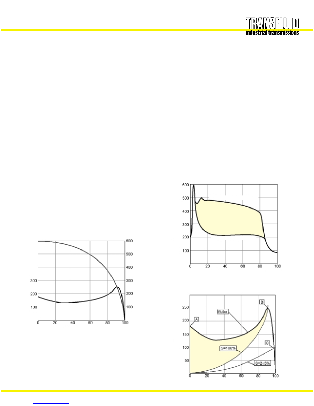
With the standard circuit in a maximum oil fill condition, fluid
couplings may transmit over 200% of the nominal motor torque. It
is possible to decrease the starting torque down to 160% of the
nominal torque, by decreasing oil fill. This, however, leads to higher
slip and working temperature in the fluid coupling, during the
steady running conditions.
The most convenient solution to provide lower starting torque while
maintaining low slip at steady running is to provide a delayed fill
chamber mounted on the main circuit. This chamber holds a
percentage of the oil which at start-up is gradually released into the
main circuit through calibrated bleed orifices as the coupling
spins.For couplings sized 15CK and above these orifices are set in
externally mounted valves.
The external mounting provides easy adjustment of the orifice size
which controls starting time and the maximum transmitted torque.
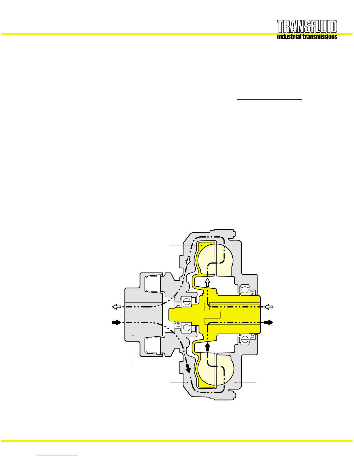
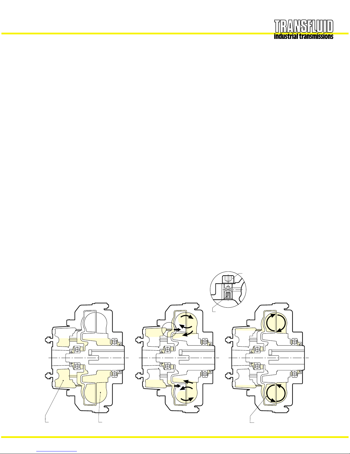
When the coupling is at rest, the delay fill chamber contains a
percentage of oil quantity in the main circuit (Fig. 4a).This reduces
the torque the coupling transmits and allows the motor to quickly
reach its steady running speed, as if it was started without load.
As the coupling accelerates, the oil flows from the delay fill
chamber to the main circuit (Fig. 4b) at a rate proportional to the
coupling’s rotational speed.
The oil continues to transfer from the delay fill chamber the to the
main circuit emptying the delay fill chamber. Once all the oil is in
the main circuit (Fig. 4c) the coupling is then transmitting 100% of
the motor torque and the minimum slip value is reached.
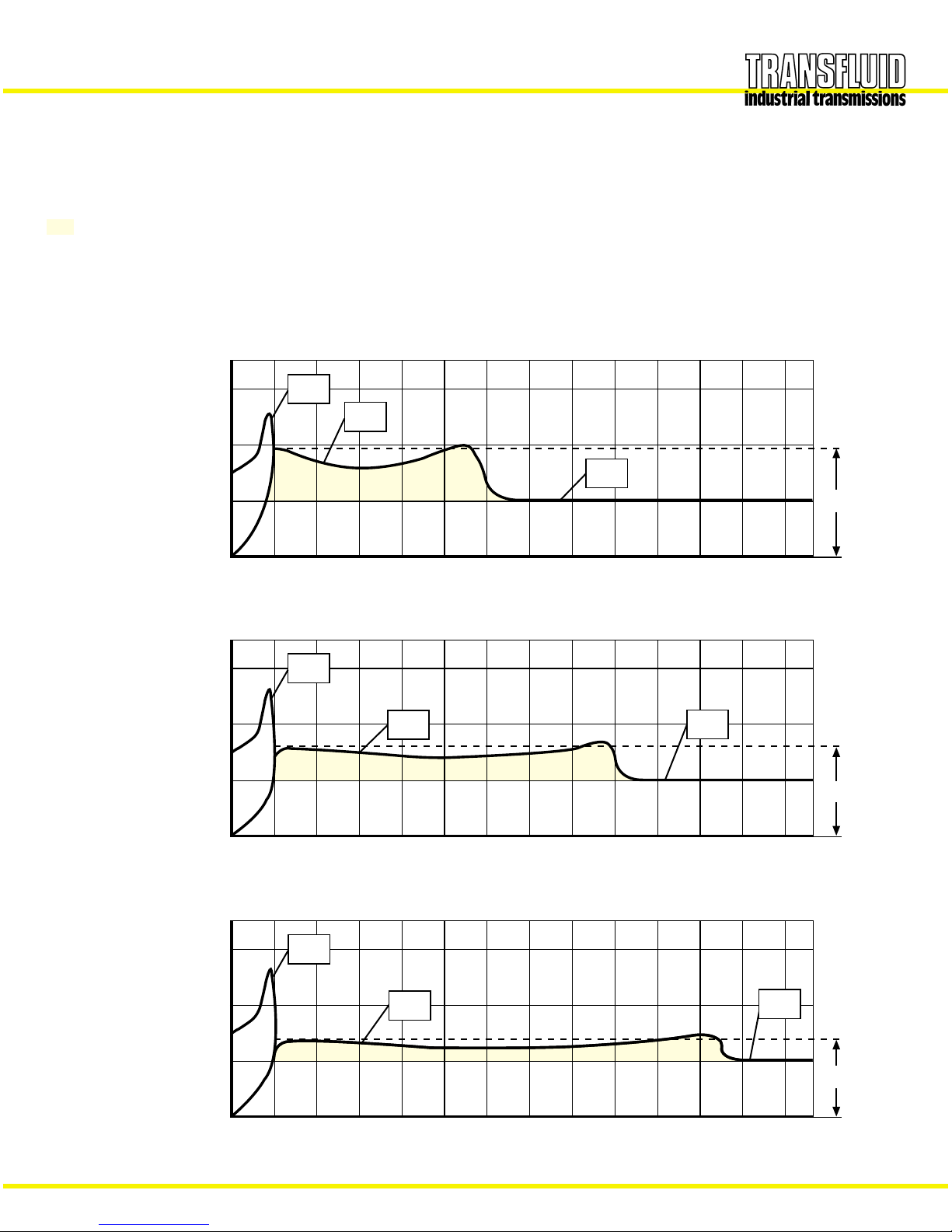
With a single delay fill chamber, the ratio between starting and
nominal torque may reach 150 %.This ratio can be reduced to 120 %
with a double delay fill chamber. This lower start-up torque
results from a smaller amount of oil in the main circuit due to more
oil in the bigger delay fill chamber.
Fluid couplings with single or double delay fill chamber provide
very smooth start-ups with low start-up torque transmission, and
this makes them excellent for applications with high inertia loads
and for use on belt conveyors.
The single size chamber is available from size 11CK and above.
The double size chamber is available from size 15CCK and above
SUMMARY OF THE ADVANTAGES GIVEN BY FLUID
COUPLINGS:
–Very smooth start-ups
–Reduction of absorbed current during the starting phase: the
motor starts with very low load
–Protection of the motor and the driven machine from jams and
overloads
–Utilization of asynchronous squirrel cage motors instead of
special motors with soft start devices
–Longer life and up time of the whole drive train, thanks to the
protection provided by the fluid coupling
–Energy saving, due to current peak reduction
–Limits starting torque to 120% with a double delayed fill
chamber
–Same torque at input and output: the motor can supply the
maximum torque even when load is jammed
–Torsional vibration absorption for internal combustion engines,
thanks to the presence of a fluid as a power transmission
element
–Possibility to achieve a high number of start-ups, or reversal of
the rotational direction.
–Load balancing with dual motor drive: fluid couplings
automatically adjust load speed to the individual motor’s speed
–High efficiency and minimum maintenance
–Viton rotating seals and O-rings
–High resistance to corrosion by using cast aluminum for the
major coupling parts and providing anticorrosion treatment on
smaller cast iron and steel parts
ACCELERATION
valve
calibrated plug
All oil in circuit
into main circuit
Oil drains from chamber
for initial start
Oil available
use after start
Oil in reserve for
Fig. 4 c
RUNNING
Fig. 4 bFig. 4 a
AT REST
Pag.4
Fig. 4 a
AT REST Fig. 4 b
ACCELERATION Fig. 4 c
RUNNING

STARTING TORQUE CHARACTERISTICS
5
CHARACTERISTIC CURVES
MI : transmitted torque from fluid coupling
Mm : starting torque of the electric motor
Mn : nominal torque at full load
...... : accelerating torque
Ktype
(standard circuit)
CK type
(circuit with a
delayed chamber)
CCK type
(circuit with a double
delayed chamber)
Mm
MI
Mn
200%
100%
0510
Time [s]
180÷200%
Torque
Mm
Mn
200%
100%
0510
Time [s]
150÷180%
Torque
MI
Mm
200%
100%
0510
Time [s]
120÷150%
Torque
MI Mn

PRODUCTION PROGRAM
Fig. F
Fig. G
21
Pag.6
STANDARD MODELS
6
KRB
CKRBP - CCKRBPCKR - CCKR
KR
CKRG - CCKRG
KRG
KDMB
KDM
CKDMBP- CCKDMBPCKDM - CCKDM
KRD EK
KCG
KCM
CKRD - CCKRD
CKCG - CCKCGCKCM - CCKCM
PRODUCTION PROGRAM
Pag.6
PRODUCTION PROGRAM
Fig. B
Fig. D
21
Fig. A
Fig. C
Fig. E
Pag.6
PULLEY
KSD-QD–CKSD-QD
: fluid coupling that will use a QD style pulley
CCKSD-QD
KSD–CKSD–CCKSD
: basic coupling that accepts a flanged pulley,
with single (CK..) or double (CCK..) delayed fill
chamber
KSI-CKSI-CCKSI : fluid coupling with an incorporated pulley,
which is fitted from inside.
KSDF-CKSDF
: basic ..KSD coupling with flanged pulley,
CCKSDF
externally mounted and therefore to be easily
disassembled.
IN LINE
KR-CKR-CCKR : Basic coupling (KR), with a single
(CKR) or double (CCKR) delayed fill
chamber.
KRG-CKRG-CCKRG :
Basic coupling with elastic coupling
KRM-CKRM-CCKRM
(clamp type), or superelastic.
KRB-CKRB-CCKRB
: like ..KRG, but with brake drum or
…KRBP brake disc.
KRD-CKRD-CCKRD
: basic coupling ..KR with output shaft. It
allows the utilization of other flex
couplings; it is possible to place it (with
a convenient housing) between the
motor and a hollow shaft gearbox.
EK : fluid coupling fitted with a bell housing, to
be placed between a flanged electric
motor and a hollow shaft gearbox.
KCM-CKCM-CCKCM
: basic coupling for half gear couplings.
KCG-CKCG-CCKCG
: basic ..KCM with half gear couplings. On
request, is available with brake drum or
brake disc.
KDM-CKDM-CCKDM
: fluid coupling with disc couplings.
…KDMB : like ..KDM, but with brake drum or
…KDMBP brake disc.
IN LINE VERSIONS MOUNTING EXAMPLES
Fig. AHorizontal axis between the motor and the driven
machine (KR-CKR-CCKR and similar).
Fig. BIt allows a radial disassembly without moving the motor
and the driven machine (KCG-KDM and similar).
Fig. CBetween a flanged electric motor and a hollow shaft
gearbox by means of a bell housing (..KRD and EK).
Fig. DVertical axis mounting between the electric motor and
a gearbox or driven machine. When ordering, please
specify mounting type 1 or 2.
Fig. E Between the motor and a supported pulley for high
powers and heavy radial loads.
PULLEY VERSIONS MOUNTING EXAMPLES
Fig. F Horizontal axis.
Fig. GVertical axis. When ordering, please specify motor shaft
pointing up (type 1) or motor shaft pointing down (type 2).
Note: The ..KCG - ..KDM versions allow a radial disassembly without moving the motor or the driven machine.
Fig. AFig. B
Fig. C
Fig. E
Fig. F
Fig. G
Fig. D
KSDF
KSI
PRODUCTION PROGRAM
KSD-QD KSD
CKSDF - CCKSDFCKSD-QD CCKSD-QD CKSD- CCKSD
Pag.6
CKSI - CCKSI

FLUID COUPLING SELECTION
7
SELECTION
SELECTION CHART
The chart below may be used to select a unit size from the
horsepower and input speed.If the selection point falls on the line
dividing one size from the other, select the larger size with a
proportionally reduced oil fill.
GENERAL REFERENCE HORSEPOWER CHART
HP kW
HORSEPOWER
INPUT SPEED RPM
THE CURVES SHOWTHE POWER CAPACITY OF COUPLING IN REFERENCETO INPUT SPEED

FLUID COUPLING SELECTION
8
MOTOR
FRAME
143T 22.275
(0.875)
145T
182T 28.575
(1.125)
184T
213T 34.925
(1.375)
215T
254 41.275
(1.625)
256T
284T 47.625
(1.875)
284TS 41.275
(1.625)
286T 47.625
(1.825)
286TS 41.275
(1.625)
324T 53.975
(2.125)
324TS 47.625
(1.875)
53.975
(2.125
60.325
(2.375)
73.025
(2.875)
85.725
(3.375)
326T
364T
365T
404T
405T
444T
445T
SHAFT DIA.
mm (inch)
1800 rpm
HP
16K
1.5 - 2
37 K
5
7.58K
10
15 9K
20
25 11 K
--
30 12 K
--
40 12 K
--
13 K
15 K
17 K
19 K
50
60
75
100
125
150
200-250
COUPLING
1200 rpm
HP
0.75 7 K
1
1.5
8 K
2
3
9K
5
7.511 K
10
15 12 K
--
20 13 K
--
25 13 K
--
15 K
17 K
19 K
21 K
30
40
50
60
75
100
125
COUPLING
900 rpm
HP
0.5 7 K
8 K
0.75
1
9 K
1.5
2
11 K
3
512 K
7.5
10 13 K
--
15 15 K
--
20 17 K
--
17 K
19 K
21 K
25
30
40
50
60
75
100
COUPLING
3600 rpm
HP
1.5 6 K
2
3
5
7.57 K
10 - 15
15 - 20 8K
20 - 25
--
30 9K
--
40 9K
--
50 9K
--
COUPLING
NON - STANDARD
MOTOR
400
600
21 K
24 K
958 27 K
1360 29 K
270 24 K
400
598
27 K
29 K
1088 34 K
1350 D 34 K
150 24 K
220
350
27 K
29 K
600 34 K
1000 D 34 K
SELECTION TABLE
Fluid couplings for standard electric motor
max max max
General note: The fluid coupling size is tied to the motor shaft dimensions
(1) Special version, 24 hours/day service
(1)

FLUID COUPLING SERIES 6 - 9 KR
9
NOTE :The arrows indicate input and ouput in the standard version.
only for size "6"
ø40
2
A
B E
C
Z
T
O
JF
Q
UN
±0.1 M
f 7
D
+0.025
P
-0
S2HOLES
R
Pag.9
W
V+0.25
-0
-0
+0.05
H7
Note:The arrows indicate input and output of the standard version.
Pag13
KR
DJWVABCEFMNOPQRSTUZ
mm. inch Nr. Ø
Weight
kg
(less oil)
Oil lt
max
•22.225 .875 57.2 4.762 24.5 195 60 90.5 29 88 *53 *4–33 68 16.5 2.7 0.5
15.875 .625 47.6 18
•34.925 1.375 79.4 7.937 38.6
28.575 1.125 63.5 6.35 31.5 228 77 124 34 7 14 5.1 0.92
22.225 .875 57 4.762 24.5 114 60 73 3 6 50 6 88
•34.925 1.375 79.4 7.937 38.6 256 91 129 30 5.5 1.5
28.575 1.125 63.5 6.35 31.5 15
•41.275 1.625 95.3 9.525 45.6 295 96 160 46 128 80 88.9 8 8 70 107 10 1.95
34.925 1.375 79.4 7.937 38.6
6
7
8
9
Size
Dimensions
1/4
20
UNC
5/16
18
UNC
7/16
14
UNC
1/2
13
UNC
3/4
10
UNC
•MAX BORE WITH A KEYWAY AS PER USAS SQUARE B17.1
*SEE DRAWING
–WHEN ORDERING, SPECIFY SIZE, MODEL AND D DIAMETER, EXAMPLE: 7 KR D. 34.925
DIMENSIONS ARE SUBJECT TO CHANGE WITHOUT NOTICE

FLUID COUPLING SERIES 6 - 9 KRG / KRB / KRBP
10
Note:The arrows indicate input and output of the standard version.
Pag13
Pag10
H
C
G
L
K
Y
XX1
ZY 1
H7
C3L1
G1
j7
KRD
NOTE :The arrows indicate input and ouput in the standard version.
KRG
KRD
DIMENSIONS ARE SUBJECT TO CHANGE WITHOUT NOTICE
_G
1SHAFT WITH SQUARE KEYWAY AS PER USAS B17.1
–UPON REQUEST: BORE G MACHINED - G1SPECIAL SHAFT
–WHEN ORDERING, SPECIFY SIZE, MODEL AND D DIAMETER, EXAMPLE: 8 KRB D.28.575
BRAKE DRUM 160 x 60
KRBP
(with brake disc)
KRB
(with brake drum)
Size
Dimensions mm
149 107 28 22.225 73 40 41.275 BT02 on request 3.9 3
201 145 42 34.925 110 2 60 50.8 BT10 160 x 60 8.3 5.7
206 150 8.7 6.1
261 191 55 47.625 132 80 63.5 BT20 160 x 60 16 11.6
200 x 75
6
7
8
9
CC
3GG
1HKLL
1Flex Brake Weight kg
coupling drum (less oil)
max
Xx Y
KRG KRD

FLUID COUPLING SERIES 11 - 34 KR / CKR / CCKR
11
O
P
TZ
Q
B E
C
S
JA
FQ R I
O
Z
T
P
U
C1
B1
N
±0.1 M
f 7
W
V+0.25
- 0
2 HOLES
D
MN
±0.1 f 7
C2
B2
7
22
6
1924 C
M16 Nr.10
M14 Nr.12
f 7
ø200
ø480
f 7
ø200
ø570
ø308
±0.1
±0.1
C2
C1
Pag.11
NOTE :The arrows indicate input and ouput in the standard version.
Note:The arrows indicate input and output of the standard version.
Pag13
KR
34 KR 34 CKR-CCKR
CKR - CCKR
DJWVABB
1B2CC
1C2EFIMNO P QRSTU Z
mm. inch Nr. Ø
47.625•• 1.875 111 12.7 50 325 107 68.5 216 42 128 195 88.9 8 6 M8
41.275 1.625 95.3 9.525 45.6 169 60 70 6 107 15
47.625•• 1.875 111 12.7 50 370 122 –236 –39 145
60.325•• 2.375 143 15.875 63 398 137 75 199 258 46 179 224 80 122.2 89 7 142 17
53.975 2.125 127 12.7 59.7 58
73.025•• 2,875 178 19.05 76
60.325 2.375 143 15.875 67.3 460 151 87 135 226 294 342 56 206 259 90 136 M10 101 156
53.975 2.125 127 12.7 59.7
85.725•• 3.375 194 22.225 92.3 520 170 62 819
73.025 2.875 178 19.05 81.4 96 176 248 328 408 225 337 125 160 15 12 126 180
85.725•• 3.375 194 22.225 92.3 565 190 42
73.025 2.875 178 19.05 81.4
98.425•• 3.875 216 25,4 104.3 620 205 71
85.725 3.375 210 22.225 95.5 110 200 286 386 476 250 400 160 228 5 M14 136 255 30
98.425•• 3,875 216 25.4 104.3 710 229 47 8 14
85.725 3.375 210 22.225 95.5
120.65•• 4,750 216 31.75 129.8 780 278 322 440 540 41 315 200 275 7 M16 185 308 33
133.35•• 5.250 241 31.75 142.7 860 295 131 231 349 467 567 350 537 205
150.8•• 5.938 265 38.1 161.2 1000 368 422 553 653 54 400 **** * 240 (2) (2) (2)
11
12
13
15
17
19
21
24
27
29
34
Size
Dimensions
3/4
10
UNC
7/16
14
UNC
7/8
9
UNC
9/16
12
UNC
1 1/4
7
UNC
5/8
11
UNC
3/4
10
UNC
1 3/4
5
UNC
7/8
9
UNC
•• MAX BORE WITH REDUCED VDEPTH KEY WAY
* SEE DRAWING
–WHEN ORDERING, SPECIFY SIZE, MODEL AND D
DIAMETER, EXAMPLE: 29 CCKR D. 133.36
up to 50.8
Dim. Dtolerance from 50.8 to 101.6
from 101.6 to 152.4
DIMENSIONS ARE SUBJECT TO CHANGE WITHOUT NOTICE
+0.025
–0+0.038
–0
+0.05
–0
up to 12.7
Dim. Wtolerance from 15.875 to 25.4
from 25.4 to 38.1
+0.05
–0+0.076
–0
+0.1
–0
Size
Dimensions
Weight Kg
(less oil) Oil
max lt
KR CKR CCKR KR CKR CCKR
12 14.5 2.75 3.35
155 18.5 –4.1 4.8 –
24 27 5.2 5.8
37 41 48.7 7.65 8.6 9.3
51 57 66 11.7 13.6 14.9
58 64 73 14.2 16.5 18. 5
87 97 105 19 23 31
105 115 129 28.4 31.2 39
161 179 198 42 50 61
214 232 242 55 63 73
350 367 377 82.5 92.5 101
11
12
13
15
17
19
21
24
27
29
34
KR CKR CCKR KR CKR CCKR

Y
KL C
H
L 1 C 3
C2
C1
G
H7
X1 X
ZY 1
C4
C5
j7
G1
CKRG - CCKRG
(WITH BRAKE DR(WITH BRAKE DRUM)
KRG
KRBP
KRB
KRD
Pag.12
(WITH BRAKE DISC)
NOTE :The arrows indicate input and ouput in the standard version.
FLUID COUPLING SERIES 11 - 34 KRG / CKRG / CCKRG / KRB / CKRB / CCKRB
KRBP / CKRBP / CCKRBP / KRD / CKRD / CCKRD
12
Note:The arrows indicate input and output of the standard version.
Pag13
–G1SHAFT WITH SQUARE KEYWAY AS PER USAS B17.1
–UPON REQUEST BORE GMACHINED - G1SPECIAL SHAFT
–WHEN ORDERING, SPECIFY SIZE, MODEL AND DDIAMETER, EXAMPLE: 17 CKRBP D. 73.025
BRAKE DISC 450 x 30 DIMENSIONS ARE SUBJECT TO CHANGE WITHOUT NOTICE
CKR - CCKR
KRD
CKRG - CCKRG
CKRD - CCKRD
KRBP
(with brake disc)
KRB
(with brake drum)
CC
1C2C3C4C5GG
1HKLL
1Flex Brake Brake Z
coupling
drum disc Weight kg
(less oil)
KRG CKRG CCKRG KRD CKRD CCKRDKRG CKRG CCKRG KRD CKRD CCKRD max
Xx YX
1xY1
270 317 200 247 55 47.625 132 2 63.5 BT20 on request –18 20.5 13 15.5
337 –267 –80 21.5 24.5 –16.7 19.7 –
303 363 230 290 70 53.975 170 89 BT30 5 34 37 26.3 29.3
364 432 480 251 319 367 80 60.325 BT40 35 50.3 54.3 62 40.4 44.4 52.1
387 467 547 288 368 448 90 73.025 250 3 110 108 BT50 15 77 83 92 58.1 64.1 73.1
84 90 99 65.1 71.1 80.1
459 559 649 318 418 508 110 85.725 290 140 127 BT60 45 129 139 147 99.5 109.5 117.5
147 157 165 117.5 127.5 135.5
509 627 727 358 476 576 130 101.6 354 4 150 139.7 BT80 500 x 190 20 231 249 268 181 189 218
536 654 754 385 503 603 284 302 311 234 252 261
630 761 861 472 603 703 160 139.7 425 5 180 152.4 CT90 630 x 265 1000 x 30 50 471 486 496 376 395 401
11
12
13
15
17
19
21
24
27
29
34
Size
Dimensions mm.
160 x 60
200 x 75
200 x 75
250 x 95
250 x 95
315 x 118
315 x 118
400 x 150
400 x 150
500 x 190
400 x 30
450 x 30
400 x 30
450 x 30
445 x 30
450 x 30
560 x 30
630 x 30
710 x 30
795 x 30
710 x 30
795 x 30

FLUID COUPLING SERIES D 34 KDM
13
Note:The arrows indicate input and output of the standard version.
Pag13
DIMENSIONS ARE SUBJECT TO CHANGE WITHOUT NOTICE
Pag13Pag13Pag13Pag13Pag13Pag13
Note :The arrows indicate input and ouput in the standard version.
Pag13
640383 377
1400
885 257.5257.5 1401120140
0
- 0.025
ø139.7
0
- 0.025
ø139.7
Pag13
170
ø1000
Pag13Pag13
Note :The arrows indicate input and ouput in the standard version.
SLIDING LOCKED
FLUID COUPLING WITH DOUBLE CIRCUIT, FITTED WITH MAIN JOURNALS AND INPUT AND OUTPUT SHAFTS
810 162
OIL
max. lt
KEYWAYS AS PER USAS B17.1
WEIGHT Kg
(less oil)
31.75 +0.1
0
122 –0.1
–0.4

FLUID COUPLING SERIES 9 - 34 KRM / CKRM / CCKRM
14
Note:The arrows indicate input and output of the standard version.
Pag13
DIMENSIONS ARE SUBJECT TO CHANGE WITHOUT NOTICE
C2
C1
EB
J
S
R F A
H7
G
H
LC
Q- 0
V+0.25
W
+0.025
- 0
D
2 HOLES
Pag14
NOTE :The arrows indicate input and ouput in the standard version.
KRM CKRM - CCKRM
DJWVABCC
1C2EFGHLQRS Flex
coupling
Weight kg
(less oil)
KRM CKRM CCKRMmm. inch. KRM CKRM CCKRM max
41.275•1.625 95.3 9.525 45.6 295 96 291 –46 14.5 –
34.925 1.375 79.4 7.937 38.6 128
47.625•• 1. 875 111 12.7 50 325 107 347 42 50 185 50 70 53 F 16.5 19
41.275 1.625 95.3 9.525 45.6 300 – –
47.625•• 1.875 111 12.7 50 370 122 367 39 145 20 23
60.325•• 2.375 143 15.875 63 398 137 351 411 46 179 65 228 72 89 55 F 33 36
53.975 2.125 127 12.7 59.7
73.025•• 2.875 178 19.05 76
60.325 2.375 143 15.875 67.3 460 151 388 456 504 56 206 70 235 80 101 56 F 48 52 59.7
53.975 2.125 127 12.7 59.7
85.725•• 3.375 194 22.225 92.3 520 170 62 67 73 82
73.025 2,875 178 19.05 81.4 405 485 565 225 75 288 90 126 58 F
85.725•• 3.375 194 22.225 92.3 565 190 42 74 80 89
73.025 2.875 178 19.05 81.4
98.425•• 3.875 216 25.4 104.3 620 205 71 124 134 142
85.725 3.375 210 22.225 95.5 522 622 712 250 90 378 110 136 65 F
98.425•• 3.875 216 25.4 104.3 710 229 47 142 152 160
85.725 3.375 210 22.225 95.3
120.65•• 4.750 216 31.75 129.8 780 278 550 668 768 41 315 100 462 122 185 66 F 214 232 251
133.35•• 5.250 241 31.75 142.7 860 295 600 718 818 350 120 530 145 205 68 F 296 314 324
150.8•• 5.938 265 38.1 161.2 1000 368 683 814 914 54 400 140 630 165 240 610 F 480 497 507
9
11
12
13
15
17
19
21
24
27
29
34
Size
Dimensions
3/4
10
UNC
7/16
14
UNC
7/8
9
UNC
9/16
12
UNC
5/8
11
UNC
1 1/4
7
UNC
3/4
10
UNC
1 3/4
5
UNC
7/8
9
UNC
•MAX BORE WITH A KEYWAY AS PER USAS B17.1
•• MAX BORE WITH REDUCED VDEPHT KEYWAY
–UPON REQUEST BORE G MACHINED
–WHEN ORDERING, SPECIFY SIZE, MODEL AND D DIAMETER, EXAMPLE: 15 KRM D. 60.325
up to 50.8
Dim. Dtolerance from 50.8 to 101.6
from 101.6
+0.025
–0+0.038
–0
+0.05
–0
up to 12.7
Dim. Wtolerance from 15.875 to 25.4
from 25.4 to 38.1
+0.05
–0+0.076
–0
+0.1
–0

FLUID COUPLING SERIES 6 - 24 KRA / CKRA / CCKRA
15
Note:The arrows indicate input and output of the standard version.
Pag13
DIMENSIONS ARE SUBJECT TO CHANGE WITHOUT NOTICE
Pag.15
Note :The arrows indicate input and ouput in the standard version.Note :The arrows indicate input and ouput in the standard version.
S
Q
G
H7
HA
BE
C
L
JF
D
2 HOLES
R
C1
C2
W
V+0.25
-0
KRA CKRA - CCKRA
DJWVABCC
1C2E F G H L Q R S Flex
coupling
Weight kg
(less oil)
KRA CKRA CCKRAmm. inch. KRA CKRA CCKRA max
•22.225 .875 57,2 4.762 24.5 195 60 140 29 88 25.4 85 32 –33 2 A - 1 S 3.2
15.875 .625 47,6 18
•34.925 1.375 79,4 7.937 38.6
28.575 1.125 63,5 6.35 31.5 228 77 186 34 6,7
22.225 .875 57,2 4.762 24.5 –114 38 120 42 50 8 A - 1 S –
•34.925 1.375 79,4 7.937 38.6 256 91 191 30 7
28.575 1.125 63,5 6.35 31.5 –
•41.275 1.625 95,3 9.525 45.6 295 96 232 46 12.3 –
34.925 1.375 79,4 7.937 38.6 128 48 151 50 16 A - 1 S
••47.625 1.875 111 12.7 50 325 107 241 288 42 70 14.3 16.8
41.275 1.625 95,3 9.525 45.6
••47.625 1.875 111 12.7 50 370 122 246 313 39 145 55 170 55 25 A - 1 S 19.5 22.5
••60.325 2.375 143 15.875 63 398 137 291 351 46 179 89 30 33
53.975 2.125 127 12.7 59.7
••73.025 2.875 178 19.05 76 65 200 66 50 A - 1 S
60.325 2.375 143 15.875 67.3 460 151 321 389 437 56 206 101 42.9 46.9 54.6
53.975 2.125 127 12.7 59.7
••85.725 3,375 194 22.225 92.3 520 170 62 63.2 69.2 78.2
73.025 2.875 178 19.05 81.4 358 438 518 225 85 260 80 126 140 A - 1 S
••85.725 3.375 194 22.225 92.3 565 190 42 70.2 76.2 85.2
73.025 2,875 178 19.05 81.4
••98.425 3.875 216 25.4 104.3 620 205 71 118 128 136
85.725 3,375 210 22.225 95.5 426 526 616 250 115 340 100 136 250 A - 1 S
••98.425 3.875 216 25.4 104.3 710 229 47 136 146 154
85.725 3.375 210 22.225 95.5
6
7
8
9
11
12
13
15
17
19
21
24
Size
Dimensions
1/2
13
UNC
1/4
20
UNC
5/16
18
UNC
3/4
10
UNC
7/16
14
UNC
7/8
9
UNC
9/16
12
UNC
5/8
11
UNC
1 1/4
7
UNC
3/4
10
UNC
•MAX BORE WITH A KEYWAY AS PER USAS B17.1
•• MAX BORE WITH REDUCED VDEPHT KEYWAY
–UPON REQUEST BORE G MACHINED
–WHEN ORDERING, SPECIFY SIZE, MODEL AND D DIAMETER, EXAMPLE: 15 KRM D, 60.325
up to 50.8
Dim. Dtolerance from 50.8 to 101.6
+0.025
–0+0.038
–0
up to 12.7
Dim. Wtolerance from 15.875 to 25.4
from 25.4 to 38.1
+0.05
–0+0.076
–0
+0.1
–0

FLUID COUPLING SERIES 6 - 11 EK
16
Note:The arrows indicate input and output of the standard version.
Pag13
DIMENSIONS ARE SUBJECT TO CHANGE WITHOUT NOTICE
EK
up to 34.925
Dim. Gtolerance from 41.925 to 47,625
+0
–0.013 +0
–0.025
•MAX BORE WITH A KEYWAY AS PER USAS B17.1
•• MAX BORE WITH REDUCED VDEPHT KEYWAY
GSHAFT SUPPLIED WITH SQUARE KEY USAS B 17.1
(2) WHEN FULL POWER IS ABSORBED USE HIGH DENSITY FIRE RESISTANT OIL
N
f7
(Nr.4x90˚)
O
V+0.25
-0
-0
+0.05
W
f7
N
D
F7 AM
H
f7
N
(Nr.4x90˚)
C
O
G
N
f7
L
M
C
Pag.16
Example of application
Pag.16
only for size “6”only for size “6”
Example of application
Size
Dimensions
•22.225 .875 50.5 24.5 22.225 50,2 4.7 145TC 1.5 - 2 (2)
15.875 .625 48 4.762 18 15.875 44,8 248 110 3.8 149.2 114.3 11 0.5 145TC 1
56C 0.75
28.575 1.125 71 6.35 31.5 28.575 47 269 132 –2.6 0.92 182TC 3
184TC 5
34.925 1.375 80 7.937 38.5 34.925 54 299 145.5 1.4 184.2 215.9 1.5 213TC 7.5
13.5 215TC 10
41.275 1,625 95.2 9.525 45.6 41.275 63 1.95 254TC 15
399 187 0 256TC 20 (2)
••47.625 1.875 111 12.7 50 47.625 73 228.6 266.7 2.75 284TC 25
286TC 30
6
7
8
9
11
DJWVGLACHMNOOilElectric Motor
max lt sizemm. inch
HP
at 1800
RPM

FLUID COUPLING SERIES 7 - 34 KCM / CKCM / CCKCM
17
F
E
H
E
H
DB DA B
F
LC
1
+0.05
0
+0.05
0
C2
C1
CKCM - CCKCM
CKM
Pag15
KCM CKCM - CCKCM
(3) S = SHROUDED BOLTS
(4) S = EXPOSED BOLTS
WHEN ORDERING, SPECIFY SIZE AND MODEL EXAMPLE: 34 CKCM
Size
Dimensions
228 116 140 95.25 6 6.4 17 7.3
256 145 –8.1 –
295 177 –7 6.5 18.5 14 –
325 152.5 186 233 122.22 8 9.57 16 18,5
370 198 265 21 21 24
398 208 283.5 28 31
460 250 329 377 24.5 47.2 51 52.9
520 250 332 412 66.2 72 81
565 213 177.8 10 12.75 9,5 10 25.5 75 81 90
620 320 422 512 109 119 127
710 129 139 147
780 280 408 526 626 241.3 206 229 239
860 437 555 655 8 19.05 22 28 50 255 278 288
1000 318 510 634 734 279.4 436 444 454
7
8
9
11
12
13
15
17
19
21
24
27
29
34
ABCC
1C2DEFF
1HL Weight kg
(less oil)
Nr. ØKCM CKCM
CCKCM
KCM CKCM
CCKCM
1/4
28
UNF
3/8
24
UNF
1/2
20
UNF
3/4
10
UNC
1”
S
1”1/2
S
2”1/2
S
3”1/2
E
4”
E
Gear
coupling
size
Note:The arrows indicate input and output of the standard version.
Pag13
(3)
(3)
(3)
(4)
(4)
DIMENSIONS ARE SUBJECT TO CHANGE WITHOUT NOTICE
THIS FLUID COUPLING MOUNTS ONE (1) HALF GEAR COUPLING ON EACH SIDE.
THIS ALLOWS THE REMOVAL OF THE FLUID COUPLING WITHOUT MOVING THE
MOTOR OR THE DRIVEN MACHINE

FLUID COUPLING SERIES 7 - 34 KCG / CKCG / CCKCG
18
NN
MI
I
G
AG
C
M1M1
M2M2
KCGKCG CKCG - CCKCGCKCG - CCKCG
Fascia o disco freno a richiesta
KCGB
(Con fascia freno)
(Con disco freno)
KCGBP
C2C2
C1C1
Pag16
NN
MI
I
G
AG
C
M1
M2
KCG CKCG - CCKCG
Fascia o disco freno a richiestaFascia o disco freno a richiesta
KCGBKCGB
(Con fascia freno)(Con fascia freno)
(Con disco freno)(Con disco freno)
KCGBPKCGBP
C2
C1
Pag16
KCG CKCG - CCKCG
KCGB
(with brake drum)
Brake drum or disc upon request
Size
Dimensions
228 229 50 43 143 44.5
256 234 –148 –
295 278.6 –180 –
325 287.6 65 49.3 236 50.8
370 299.6 201 268
398 309.6 385.1 211 286.5
460 407 486 534 255 334 382
520 409 491 571 255 337 417
565 95 77 79.5
620 479 581 671 325 427 517
710
780 627 745 845 134 106.5 414 532 632 109.5
860 656 774 874 443 561 661
1000 757 881 981 160 120.5 516 640 740 123.5
7
8
9
11
12
13
15
17
19
21
24
27
29
34
ACC
1C2GIMM
1M2N
KCG CKCG CCKCG max KCG CKCG CCKCG
1”
S
1”1/2
S
2”1/2
S
3”1/2
E
4”
E
(3)
(3)
(3)
(4)
(4)
Gear coupling
Size Weight Kg
(3) S = SHROUDED BOLTS
(4) S = EXPOSED BOLTS
WHEN ORDERING, SPECIFY SIZE AND MODEL EXAMPLE: 34 CKCG
Note:The arrows indicate input and output of the standard version.
Pag13
THIS FLUID COUPLING MOUNTS ONE (1) HALF GEAR COUPLING ON EACH SIDE.
THIS ALLOWS THE REMOVAL OF THE FLUID COUPLING WITHOUT MOVING THE
MOTOR OR THE DRIVEN MACHINE
DIMENSIONS ARE SUBJECT TO CHANGE WITHOUT NOTICE
4
8
23.5
56.6
81.5
KCGBP
(with brake disc)
This manual suits for next models
16
Table of contents