GB/USA
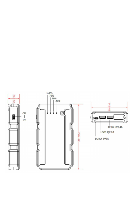
Attention: The jump starter will perform at its full capacity when it’s
100 % charged. Turn on your jump starter and make sure it‘s over
25 % charged.
F15 Clamp Cable User Manual
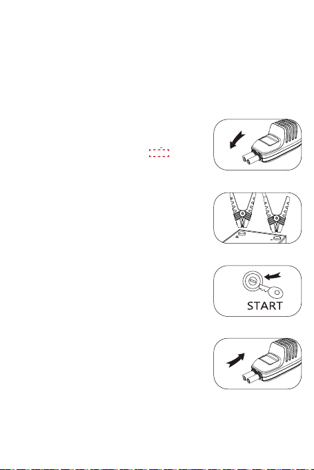
Step 1:
Insert QDSP clamp cable to jump starter EC5
jump-starting port, switch on the jump starter
power, wait until the clamp cable is in stand-
by status. When it is stand-by status,
is on and ashing in circle, now the
jump starter is ready for jump-starting.
Step 2:
Connect the clamp cable to car battery. Red
clamp cable goes to positive, black clamp
cable goes to negative, please pay attention
to the right polarity terminal and avoid reverse
connection.
Step 3:
When it goes to the jump-starting standby
status, the LCD display on clamp cable will
show the jump starter voltage. Loading is
tested every 5 sec; charging & loading is cut
off after 20 secs.
Step 4:
After jump-starting the engine, remove the
jump starter rst, then disconnect the clamp
cable.
by status. When it is stand-by status,
is on and ashing in circle, now the
-by status, “ ” is on and flashing in circle, now the
is on and ashing in circle, now the
-by status, “ ” is on and flashing in circle, now the
is on and ashing in circle, now the
is on and ashing in circle, now theis on and ashing in circle, now the
is on and ashing in circle, now theis on and ashing in circle, now the
is on and ashing in circle, now theis on and ashing in circle, now the
is on and ashing in circle, now theis on and ashing in circle, now the
is on and ashing in circle, now theis on and ashing in circle, now the
is on and ashing in circle, now theis on and ashing in circle, now the
is on and ashing in circle, now theis on and ashing in circle, now the
is on and ashing in circle, now theis on and ashing in circle, now the
F15 Clamp Cable User Manual
Step1
Insert QDSP clamp cable to jump starter EC5 jump-starting port, swiitch on the jump
starter power, wait until the clamp cable is in stand-by status. When it is in the stand
-by status, “ ” is on and flashing in circle, now the jump starter is ready for
jump-starting.
Step 2
Connect the clamp cable to car battery. Red clamp cable connects to positive “+”,
black clamp cable connects to negative “-“. Please pay attention to the right polarity
terminal and avoid reverse connection.
Step 3
When it is on stand-by status, the LCD display will show the voltage of the jump
starter. Loading is tested every 5 sec; charging & loading is cut off after 20 secs.
Step 4
After jump-starting the engine, remove the jump starter first, then disconnect ten
clamp cable.