See the entire line of Klamp System
TM
Components at:
WWW.KREGTOOL.COM
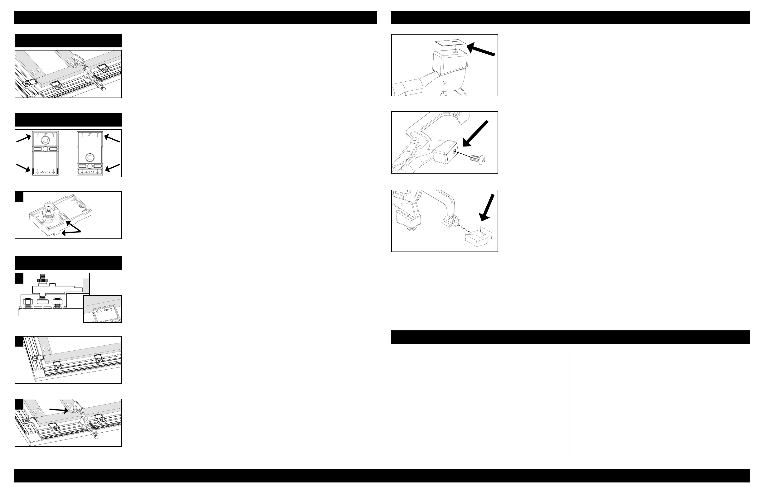
The Glide Pad.
This pad allows the Bench Klamp™ to slide smoothly across the Klamp Trak™ and Klamp Plate™.
Begin by using a dry cloth or paper towel to remove any excess oil from the base of the Klamp.
Separate the Plastic Glide Pad from its paper backing. Then, carefully center and adhere the pad
to the base of the Bench Klamp™, as shown at left. Any part of the pad which extends beyond
the Bench Klamp™’s base may be trimmed off.
The Clamp Pad.
The Clamp Pad protects your workpieces from being marred or otherwise damaged by the Bench
Klamp™. Depending on the type of work you are doing, and the hardness of your stock, you may
add or remove the Clamp Pad at your discretion.
The Anchoring Screw.
This Inter-Lok Anchoring Screw serves as the foundation of the entire Klamp System™. With it,
the Bench Klamp™ can be moved to the Klamp Plate™ and Klamp Trak™ quickly and easily, and
removed again to retain a flat work surface. Begin by threading the Anchoring Screw into the
base of the Bench KlampTM. Start with the Anchoring Screw roughly ½ of the way in, and test
the fit on the Klamp Plate™ or Klamp Trak™. Continue to adjust the Anchoring Screw until it
‘slip-fits’ into the slot without difficulty, and still rotates freely.
Bench KlampTM Instructions
Introduction
Our Klamp BlocksTM are designed to allow for quick registration of your workpieces to
the edge of the Klamp Trak™ and to precisely center joints under the Bench Klamp’sTM
rubber pad.
To center the Bench Klamp™ on joints in a repeatable fashion, the Klamp BlocksTM must
first be set correctly. There are 4 dimensions listed on each Klamp BlockTM (1-½”, 2”,
2-½”, 3”), which relate to the width of your stock to be joined. For instance, if you
are working with 1-1/2” wide stock, positioning your blocks with the 1-1/2” marking
adjacent to the stock will place the center of your Bench Klamp™ on the joint line
between mating workpieces.
Getting Started
To set your Klamp Blocks™, start by finding your stock’s width and locating the same
dimension on your Klamp Block™. (We will be using 1-1/2” wide stock in this example.)
Then, insert the t-bolt into the Alignment Tab opposite the marking, as shown in
image 1. Once the Bolt is through, thread the plastic nut onto the bolt so that the
bolt slightly protrudes from the other side. Repeat as necessary to the remaining
Klamp Blocks.
Clamping a Joint
With the correct marking facing your workpiece, insert your Klamp Block™ into the
t-slot of the Klamp Trak™, as shown in image 3.
4.
5.
The Klamp Block™ will now slide in either direction along the length of the trak.
Position the block in its desired location and lock it into place by tightening the plastic
nut. Add a second block to the trak and slide your workpiece up against them, parallel
to the trak, as shown in image 4.
Now that your workpiece is in place parallel to the Trak, the center of the Bench
Klamp’sTM clamp pad will be perfectly centered on the far side of the workpiece, making
it easy to clamp on the center of any joint. This is especially useful for Pocket-Screw
Joinery, as shown in image 5.
3.
1.
Alignment Tabs
Klamp BlocksTM Instructions
Cleaning
The slick melamine coating on the Table Top does a
good job of resisting glue but may need some basic
cleaning from time to time. Cleaning the surface
frequently and keeping it free from build-up will
lengthen the life of the top and keep the surface as
smooth/useful as possible. For additional protection
against glue, we recommend coating the surface with
Bates Glue Release (1-888-363-2628). Be sure to follow
the respective product’s directions during application.
Replacement Top
In the event that a replacement top for your Klamp
Table™ is required, contact Kreg directly. Our customer
service professionals will be able to help you order your
replacement top and will get it sent to you as soon as
possible.
Klamp TableTM Maintenance
800.447.8638


