KRESS PK 450 HM User manual

Pneumatik-
Bohrhammer
Pneumatic Drill Hammer
Perforateur pneumatique
PK 450 HM
Bedienungsanleitung
Operating Instructions
Mode d’emploi
30805/0304 HD
PK 450 HM - D +GB+F Seite 1 Donnerstag, 24. Januar 2002 9:03 09

1 Werkzeugaufnahme
2 Staubschutzkappe
3 Entriegelungshülse
4 Umschalter
Bohren/Hammerbohren
5 Lüftungsschlitze
6 Ein-/Ausschalter
7 Feststellknopf Ein-/Ausschalter
8 Drehrichtungsumschalter
9 Adapter
Abgebildetes oder beschriebenes Zubehör
muss nicht zum Lieferumfang gehören.
Verwendung
Der Pneumatik-Bohrhammer ist uni-
versell einsetzbar zum Hammerboh-
ren und zum Bohren sowie Schrau-
ben in Holz, Metall und Kunststoff.
Für Meißelarbeiten (auch mit Spitz-
meißel) ist dieser Pneumatik-Bohr-
hammer nicht geeignet.
Sicherheitshinweise und
Unfallschutz
Bevor Sie die Maschine in Betrieb
nehmen, lesen Sie die Bedienungs-
anleitung vollständig durch und be-
folgen Sie die Sicherheitshinweise in
dieser Anleitung.
• Wird das Netzkabel während der
Arbeit beschädigt, sofort Netz-
stecker ziehen.
• Niemals mit beschädigtem Netz-
kabel arbeiten.
• Schutzbrille, Gehörschutz, Schutz-
handschuhe und festes Schuhwerk
tragen.
• Kein asbesthaltiges Material bear-
beiten.
• Gerät nicht am Kabel tragen.
• Steckdosen im Außenbereich müs-
sen über Fehlerstromschutzschal-
ter (FI-) abgesichert sein.
• Um die Maschine zu kennzeichnen,
darf das Gehäuse nicht angebohrt
werden. Die Schutzisolation wird
überbrückt. Verwenden Sie Klebe-
schilder.
• Wenn der Bohrer unerwartet fest-
klemmt, reagiert die Maschine ruck-
artig. Nehmen Sie deshalb immer
einen sicheren Stand ein und halten
Sie die Maschine fest mit beiden
Händen.
Technische Daten PK 450 HM
Aufnahmeleistung 450 W
Abgabeleistung 225 W
Anbohrstufe ja
Rechts-/Linkslauf ja
Leerlaufdrehzahl 800/950 min-1
Lastdrehzahl 770 min-1
Leerlaufschlagzahl max. 4700 1/min
Lastschlagzahl max. ca. 4000 1/min
Schlagenergie max. 1,8 J (Joule)
Spannhals-Ø 43 mm
Werkzeugaufnahme SDS-Plus
Empfohlener
Bohrbereich 5-10 mm
Hammerbohrleistung max. 16 mm
Bohr-Ø max.
Stahl 13 mm
Leichtmetall 16 mm
Holz 25 mm
Hammerbohren in Beton 16 mm
Schrauben-Ø max.
Holz 6 mm
Blech 6,3 mm
Eckmaß 33 mm
Gewicht 2,2 kg
Schutzklasse II /
Deutsch
1 2 34 56
5
8
7
PK 450 HM - D +GB+F Seite 2 Donnerstag, 24. Januar 2002 9:03 09

Inbetriebnahme
Prüfen Sie vor Inbetriebnahme, ob
die Netzspannung mit der Angabe
auf dem Typenschild des Gerätes
übereinstimmt.
Ein-/Ausschalten
Den Ein-/Ausschalter 6 drücken
bzw. wieder loslassen.
Der Ein-/Ausschalter kann mit dem
Feststellknopf 7 arretiert werden.
Zum Lösen den Ein-/Ausschalter 6
kurz drücken und loslassen.
Bohren - Hammerbohren
Zum Bohren den Umschalter 4 auf
stellen.
Zum Hammerbohren auf stellen.
Die Umschaltung lässt sich am bes-
ten im Stillstand vornehmen. Nach
Betätigung des Ein-/Ausschalters 6
bzw. beim Anlaufen der Maschine
schaltet das Getriebe in die vorge-
wählte Einstellung.
Hinweise: Linkslauf beim Hammer-
bohren beschädigt den Bohrer.
Verwenden Sie beim Hammerboh-
ren ausschließlich hartmetallbe-
stückte Bohrer mit SDS plus-
Schaft. Die Verwendung handelsüb-
licher Steinbohrer mit zylindrischem
Schaft unter Verwendung des Adap-
ters 9 und eines üblichen Bohrfutters
unter Einsatz des pneumatischen
Hammerwerkes ist nicht möglich.
Drehzahlsteuerung
Mit dem Ein-/Aus-
schalter 6 können
zwei Drehzahlstufen
gewählt werden.
Zum Anbohren den Ein-/Ausschal-
ter 6 leicht drücken (Anbohrstufe), für
volle Bohrleistung den Schalter 6
ganz drücken.
Drehrichtung umschalten
Betätigen Sie den
Drehrichtungsum-
schalter 8 nur im
Stillstand!
Greifen Sie den Drehrichtungsum-
schalter 8 beidseitig.
Rechtslauf:
Drehrichtungsumschalter 8 auf „R“
stellen.
Linkslauf:
Drehrichtungsumschalter 8 auf „L“
stellen.
Wichtig: Drehrichtungsumschal-
ter 8 jeweils bis zum Anschlag am
Gehäuse durchdrücken, d. h., bis er
spürbar einrastet.
Steht der Drehrichtungsumschal-
ter 8 zwischen Pos. „R“ und „L“,
kann die Maschine nicht einge-
schaltet werden.
Werkzeug entnehmen/einsetzen
Die Werkzeugaufnahme 1 spannt
Bohrwerkzeuge ohne Werkzeug-
schlüssel.
Werkzeug einsetzen
• Ziehen Sie vor allen Arbeiten am
Gerät den Netzstecker.
Reinigen Sie den Werkzeugschaft
und fetten Sie ihn leicht.
Ziehen Sie die Entriegelungshülse 3
zurück. Führen Sie das Werkzeug
drehend in die Werkzeugaufnahme
ein, bis es einrastet. Lassen Sie die
Entriegelungshülse los. Prüfen Sie
das Werkzeug auf festen Sitz.
Achten Sie darauf, dass die Staub-
schutzkappe 2 nicht beschädigt wird.
Beschädigte Staubschutzkappe
unbedingt ersetzen!
Werkzeug entnehmen
Schieben Sie die Entriegelungs-
hülse 3 nach hinten und ziehen Sie
das Werkzeug heraus.
Bohrfutter (Zubehör)
Für Bohrarbeiten in Metall, Holz und
Kunststoff mit Bohrern mit normalem
Schaft, ist ein Bohrfutter (max.13 mm
Spannweite) lieferbar. Das Bohrfutter
wird auf den Adapter 9 (Zubehör) für
Schraub-Bits montiert. Es können
alle üblichen Bohrfutter mit Innenge-
winde 1/2" ×20 UNF (Spannweite
max.13 mm) verwendet werden.
Bohrfutter montieren
• Ziehen Sie vor allen Arbeiten am
Gerät den Netzstecker.
Gewinde am Bohrfutter (Zubehör)
und am Adapter 9 (Zubehör) reini-
gen.
Schrauben Sie das Bohrfutter auf
den Adapter und ziehen Sie es fest
(ca. 30 Nm). Zum Festziehen den
Adapter zum Beispiel in einen
Schraubstock spannen. Im Bohrfut-
ter einen Sechskantschlüssel fest-
spannenundmitdiesemdasBohrfut-
ter festziehen. Verriegeln Sie dann
den Adapter wie einen Bohrer in der
Werkzeugaufnahme.
SPEED
Fett
3
9
PK 450 HM - D +GB+F Seite 3 Donnerstag, 24. Januar 2002 9:03 09

Für die PraxisBohren Sie nicht in
verdeckt liegende
elektrische Leitun-
gen, Gas- und Was-
serrohre. Untersu-
chenSievorherdiezubearbeitenden
Flächen; zum Beispiel mit einem Me-
tallortungsgerät.
Verwenden Sie für Metall nur ein-
wandfrei geschärfte Bohrer, für Stein
und Beton nur hartmetallbestückte
Gesteinsbohrer.
Für genaues Arbeiten in Metall und
Holz die Maschine in einen Bohrstän-
der (Zubehör) setzen.
Hammerbohren
Beim Hammerboh-
ren nur mit Schutz-
brille und Gehör-
schutz arbeiten.
Üben Sie keinen zu starken Anpress-
druck aus. Die Leistung wird dadurch
nicht erhöht.
• Prüfen Sie vor der Inbetriebnahme,
ob der Umschalter 4 in Stellung
eingerastet ist.
In Fliesen bohren
Eine Fliese langsam anbohren. Erst
wenn die Fliese durchbohrt ist, auf
Hammerbohren umstellen.
Schrauben
Der Adapter 9 (Zubehör) kann
Schraub-Bits aufnehmen. Es können
handelsübliche Bits eingesetzt wer-
den mit dem Sechskantmaß 6,3 mm
bzw. 1/4" (DIN 3126, Form C).
Schraub-Bits werden im Adapter
durch einen Federring gehalten.
Deswegen nur Bits mit Kerben ein-
setzen.
Rutschkupplung
Klemmt oder hakt das Bohrwerk-
zeug, löst die Rutschkupplung aus.
Entlasten Sie sofort die Maschine, in-
dem Sie das Bohrwerkzeug zurück-
ziehen.
Halten Sie die Maschine immer fest
mit beiden Händen und nehmen Sie
einen sicheren Stand ein.
Lärm-/Vibrationsinformation
Messwerte ermittelt entsprechend
EN 50 144.
Schalldruckpegel: 83,5 dB (A)
Schalleistungspegel: 96,5 dB (A)
Arbeitsplatzbezogener
Emissionswert: 86,5 dB (A)
Für den Bedienenden sind Schall-
schutzmaßnahmen erforderlich.
Die bewertete Beschleunigung
beträgt typischerweise 12 m/s2.
Umweltschutz
Kress nimmt ausgesonderte Maschi-
nen zurück zum ressourcen-scho-
nenden Recycling. Durch Ihre modu-
lare Bauweise können Kress-Ma-
schinen sehr einfach in ihre
wiederverwertbaren Grundwerk-
stoffe zerlegt werden.
Geben Sie Ihre ausgesonderte
Kress-Maschine beim Handel ab
oder schicken Sie sie direkt an Kress.
– Änderungen vorbehalten –
1 Tool holder
2 Dust protection cap
3 Unlocking collar
4 Drilling/Impact drilling selector
5 Ventilation slots
6 On/Off switch
7 Locking button for On/Off switch
8 Rotational direction switch
9 Adapter
Accessories illustrated or described are
not always included as standard delivery
items.
Application
The pneumatic drill hammer is uni-
versally usable for hammer drilling
and drilling as well as for screwdriv-
ing in wood, metal and plastic. This
pneumatic drill hammer is not suited
for chiselling work (also not with
pointed chisels).
Safety Instructions and Accident
Prevention
Before putting the machine into oper-
ation, read through these operating
instructions completely and observe
the safety instructions.
• If the mains cable is damaged while
working, pull the mains plug imme-
diately.
• Never work with a damaged mains
cable.
• Wear protective glasses, hearing
protection, protective gloves and
sturdy shoes.
• Do not work with materials contain-
ing asbestos.
Technical data PK 450 HM
Input power 450 W
Output power 225 W
Hole starting step yes
Right/Left rotation yes
No-load speed 800/950 RPM
Speed under load 770 RPM
No-load impact rate
max. 4700 RPM
Load hammer blows
max. approx.
4000 RPM
Impact energie max. 1.8 J (Joule)
Clamping collar dia. 43 mm
Tool holder SDS-Plus
Recommended
drilling range 5-10 mm
Hammer drilling capacity max. 16 mm
Drill dia., max.
Steel 13 mm
Light metal 16 mm
Wood 25 mm
Hammer drilling in
conctrete 16 mm
Screw dia., max.
Wood 6 mm
Sheet metal 6.3 mm
Corner measure 33 mm
Weight 2.2 kg
Protection class II /
English
PK 450 HM - D +GB+F Seite 4 Donnerstag, 24. Januar 2002 9:03 09

• Do not carry the machine by the ca-
ble.
• The mains receptacles in the work-
ing area must be protected by a re-
sidual current circuit breaker (RC).
• For the attachment of identification
markings on the machine, do not
drill into the housing. The protective
insulation would be shorted. Use
stickers.
• When the drill unexpectedly jams,
the machine kicks back. Therefore,
always take a secure stance and
hold the machine firmly with both
hands.
Putting into Operation
Check before putting into operation
that the mains voltage agrees with
the voltage specified on the name-
plate of the machine.
Switching On/Off
Press or release the On/Off switch 6.
The On/Off switch can be locked on
with the locking button 7. To release,
briefly press and release the On/Off
switch 6.
Drilling - Impact drilling
For drilling, place the selector 4 in the
position.
For impact drilling, set to . The
switch-over can best be performed at
a standstill. Only after the On/Off
switch 6 is actuated and the machine
starts does the gear box shift to the
selected mode.
Note: Left rotation when impact drill-
ing damages the drill.
When hammer drilling, use exclu-
sively drills with hard metal in-
serts and SDS-Plus shafts. The
use of commercially available ma-
sonry drills with cylindrical shafts by
means of the adapter 9 and the nor-
mal drill chuck in conjunction with the
pneumatic impact mechanism is not
possible.
Speed control With the On/Off
switch 6, two speed
steps can be se-
lected.
For hole starting, press the On/Off
switch 6 lightly (hole starting step).
For full drilling performance, press in
the On/Off switch 6 completely.
Rotational direction switching
Operate the rota-
tional direction
switch 8 only when
the machine is at a
standstill!
Take hold of the rotational direction
switch 8 on both sides.
Right rotation:
Set the rotational direction switch 8
to “R”.
Left rotation:
Set the rotational direction switch 8
to “L”.
Important! Press the rotational di-
rection switch 8 in each case to the
stop on the housing, i. e. until it can
be felt to engage.
If the rotational direction switch 8
is set between the positions “R”
and “L”, the machine cannot be
switched on.
Inserting/Removing Tools
The tool holder 1 clamps the drilling
tools without using a tool key.
Inserting Tools
• Before any work on the machine
itself, pull the mains plug!
Clean and lightly grease the tool
shaft.
Pull back the unlocking collar 3. In-
sert the tool while turning into the tool
holder until it latches. Release the
unlocking collar. Check whether the
tool is firmly seated.
Take care that the dust protection
cap 2 is not damaged.
Replace damaged dust protection
caps!
Removing Tools
Slide the unlocking collar 3 to the
rear and pull out the tool.
Drill Chuck (Accessory)
For drilling work in metal, wood and
plastic with drills that have normal
shafts, a drill chuck (13 mm max.
chuck opening) is available. The drill
chuck is mounted on the adapter 9
(accessory) for screwdriver bits. All
common drill chucks with
1/2" x 20 UNF internal threads
(13 mm max. chuck opening) can be
used.
Mounting the chuck
• Before any work on the machine
itself, pull the mains plug!
Clean the threads of the drill chuck
(accessory) and the adapter 9 (ac-
cessory).
Screw the drill chuck onto the
adapter and tighten firmly (approx.
30 Nm). Clamp in a vise for tighten-
ing the adapter, for example. Clamp
anAllen keyin thedrill chuckand use
it to tighten the chuck. Then lock the
adapter in the tool holder the same
as a drill.
SPEED
Fett
3
9
PK 450 HM - D +GB+F Seite 5 Donnerstag, 24. Januar 2002 9:03 09

Practical TipsDo not drill into hid-
den electrical lines or
gas and water pipes.
Check the area to be
worked with a metal
detector,forexample,
before starting.
For metal, use only flawless, sharp-
ened drills; for stone and concrete,
only masonry drills with hard metal
inserts.
For precision working with metal and
wood, place the machine in a drill
stand (accessory).
Hammer-Drilling
For hammer drill-
ing, work only with
protective glasses
and hearing protec-
tion.
Do not apply to much pressure. The
performance is not increased in this
manner.
• Check before putting into operation
if the shift knob 4 is latched in the
position.
Drilling in Tiles
Start drilling slowly on the tile. After
the tile is drilled through, switch to im-
pact drilling.
Screwdriving
Screwdriver bits can be inserted into
the adapter 9 (accessory). Commer-
cially available bits with a hexagonal
dimension of 6.3 mm or 1/4"
(DIN 3126, Form C) can be used.
The screwdriver bits are held in the
adapter with a spring ring. Therefore,
use only bits with a notch.
Slip Clutch
If the drilling tool become jammed or
get caught, the slip clutch releases.
Remove the load from the machine
immediately by pulling back the drill-
ing tool.
Always hold the machine tightly with
both hands and assume a secure
stance.
Noise/Vibration Information
Measured values determined ac-
cording to EN 50 144.
Sound pressure level: 83.5 dB (A)
Sound power level: 96.5 dB (A)
Workplace related
emission value: 86.5 dB (A)
For operation, noise protection
measures are required.
The typical weighted
acceleration is 12 m/s2.
Environmental Protection
Kress takes back worn-out machines
for the purpose of resource-saving
recycling. As a result of their modular
construction, Kress machines can be
very easily dismantled into their reus-
able materials.
Give your worn-out Kress machine to
your dealer or send it directly to
Kress.
–
Subject to change without notice –
Garantie
1. Dieses Elektrowerkzeug wurde mit hoher Präzision gefertigt und unterliegt
strengen werkseitigen Qualitätskontrollen.
2. Daher garantieren wir die kostenlose Beseitigung von Fabrikations- oder Ma-
terialfehlern, die innerhalb von 24 Monaten ab Verkaufsdatum an den Endver-
braucher auftreten. Wir behalten uns vor, defekte Teile auszubessern oder
durch neue zu ersetzen. Ausgetauschte Teile gehen in unser Eigentum über.
3. Unsachgemäße Verwendung oder Behandlung sowie die Öffnung des Gerä-
tes durch nicht autorisierte Reparaturstellen führen zum Erlöschen der Garan-
tie. Dem Verschleiß unterworfene Teile sind von Garantieleistungen ausge-
schlossen.
4. Garantieansprüche können nur bei unverzüglicher Meldung von Mängeln
(auch bei Transportschäden) anerkannt werden. Durch Ausführung von Ga-
rantieleistungen wird die Garantiezeit nicht verlängert.
5. Bei Störungen bitte Gerät mit ausgefüllter Garantiekarte und kurzer Mängel-
beschreibung an uns oder die zuständige Servicestelle einsenden. Kaufbeleg
beifügen.
6. Durch die von uns übernommenen Garantie-Verpflichtungen werden alle wei-
tergehenden Ansprüche des Käufers – insbesondere das Recht auf Wande-
lung, Minderung oder Geltendmachung von Schadenersatzansprüchen – aus-
geschlossen.
7. Dem Käufer steht jedoch nach seiner Wahl das Recht auf Minderung (Herab-
setzung des Kaufpreises) oder Wandelung (Rückgängigmachung des Kauf-
vertrages) zu, falls es uns nicht gelingt, evtl. auftretende Mängel innerhalb ei-
ner angemessenen Frist zu beseitigen.
8. Nicht ausgeschlossen sind die Schadenersatzansprüche nach den §§ 463,
480 Abs. 2, 635 BGB wegen Fehlens zugesicherter Eigenschaften.
9. Die Bestimmungen nach Punkt 7 und 8 gelten nur für den Bereich der Bun-
desrepublik Deutschland.
Guarantee
This electro-tool was manufactured with high precision and subjected to rigorous
factory quality controls. We guarantee for material and workmanship within 24
months from date of sale. Guarantee is disclaimed in case of improper use (not
according to our instructions) or dismantling of machine by unauthorized person.
Incaseof breakdownsendmachine post-freetoour companyorto Service-Agent
of your country and attach completed guarantee slip. We have no other obligation
concerning this tool. We hope you will enjoy working with your machine.
Garantie
Cet outillage électroportatif a été construit de manière très précise et a fait, en
usine, l’objet de contrôles de qualité très stricts. Nous le garantissons contre tout
défaut de matière ou vice de construction, respectivement pendant 24 mois, à da-
ter de son expédition. Conformément à l’usage, cette garantie se limite au rem-
placement, en nos ateliers, des pièces défectueuses. Cette garantie ne sera pas
accordée, si des personnes non autorisées ont procédé ellesmêmes aux rempla-
cements de pièces de cet outil et l’on démonté. En cas de réparation, l’appareil
doit nous être envoyé franco de port. Aucune autre prétention, quant a notre re-
sponsabilité, ne sera admise. Nous vous souhaitons beaucoup de plaisir et de
succès dans votre travail.
PK 450 HM - D +GB+F Seite 6 Donnerstag, 24. Januar 2002 9:03 09

1 Fixation de l’outil
2 Capuchon anti-poussières
3 Bague de verrouillage
4 Commutateur perçage
simple/avec percussion
5 Ouïes de refroidissement
6 Interrupteur Arrêt/Marche
7 Cran d’arrêt de l’interrupteur
Arrêt/Marche
8 Commutateur du sens de
rotation
9 Adaptateur
Les accessoires reproduits et décrits dans
la notice d’instruction ne sont pas forcé-
ment compris dans les fournitures.
Utilisation
Le perforateur pneumatique est d’un
usage universel, par exemple pour le
perçage, le perçage en frappe ainsi
que le vissage dans le bois, le métal
et les matières plastiques.Ce perfo-
rateur pneumatique (même muni
d’un burin pointu) n’a pas été conçu
pour des travaux de burinage.
Consignes de sécurité et préven-
tion des accidents
Lire attentivement l’ensemble de la
notice d’utilisation avant de mettre la
machine en service. Suivre les consi-
gnes de sécurité spécifiques figurant
dans la présente notice.
• Si le cordon d’alimentation est en-
dommagé pendant un travail, ex-
traire immédiatement la fiche du
cordon d’alimentation hors de la
prise électrique.
• Ne jamais travailler avec un cordon
d’alimentation endommagé.
Garantie-Karte
Guarantee card
Bon de Garantie
Bitte sofort ausfüllen und aufbewahren.
Please fill in immediately and keep in safe place.
Veuillez remplir aussitôt et conserver.
Käufer/ Purchaser/Acheteur: Verkauft durch / Dealers name / Vendeur:
Kaufdatum:
Date purchased:
Date d’achat:
Serie No.:
Serial No.:
No. de serie:
Typ:
Type:
Type: PK 450 HM Fabrikations-Nr.:
Manufacturing No.:
Fabrication No.:
Caractéristiques
techniques PK 450 HM
Puissance absorbée 450 W
Puissance débitée 225 W
Position de centrage oui
Rotation droite et
gauche oui
Vitesse à vide 800/950 min-1
Régime en charge 770 min-1
Fréquence de frappe
à vide max. 4700 1/min
Fréquence de frappes
en charge max. env.
4000 1/min
Travail per coup max. 1,8 J (Joule)
Ø du collet de broche 43 mm
Fixation de l’outil SDS-Plus
Plage de perçage
recommandée 5-10 mm
Puissance de frappe max. 16 mm
Ø max. des foret
Dans l’acier 13 mm
Dans les alliages légers 16 mm
Dans le bois 25 mm
Travaux de perçage
dans le béton avec le
marteau perforateur 16 mm
Ø max. des vis
Dans le bois 6 mm
Dans la tôle 6,3 mm
Mesure angulaire 33 mm
Poids 2,2 kg
Classe de protection II /
Français
PK 450 HM - D +GB+F Seite 7 Donnerstag, 24. Januar 2002 9:03 09

• Porter une paire de lunettes de sé-
curité, une protection acoustique,
une paire de gants de travail ainsi
qu’une paire de solides chaussures.
• Ne pas travailler les matériaux con-
tenant de l’amiante.
• Ne jamais porter l’appareil par son
cordon d’alimentation.
• Les prises électriques situées en
extérieur doivent être protégées par
un disjoncteur à courant de défaut.
• Ne jamais percer le carter de cet ap-
pareil dans le but de le marquer ou
de l’identifier. Cela court-circuiterait
le dispositif d’isolation électrique.
Utiliser plutôt un autocollant.
• Lorsque le foret de la perceuse se
coince sans préavis dans un maté-
riau, la machine réagit brutalement.
Il convient donc de toujours adopter
une position de travail sûre et stable
et d’utiliser ses deux mains pour
maintenir fermement la machine en
position.
Mise en service
Avant de mettre l’appareil en service,
toujours s’assurer au préalable que
la tension fournie par le secteur coïn-
cide bien avec celle qui est indiquée
sur la plaquette signalétique de l’ap-
pareil.
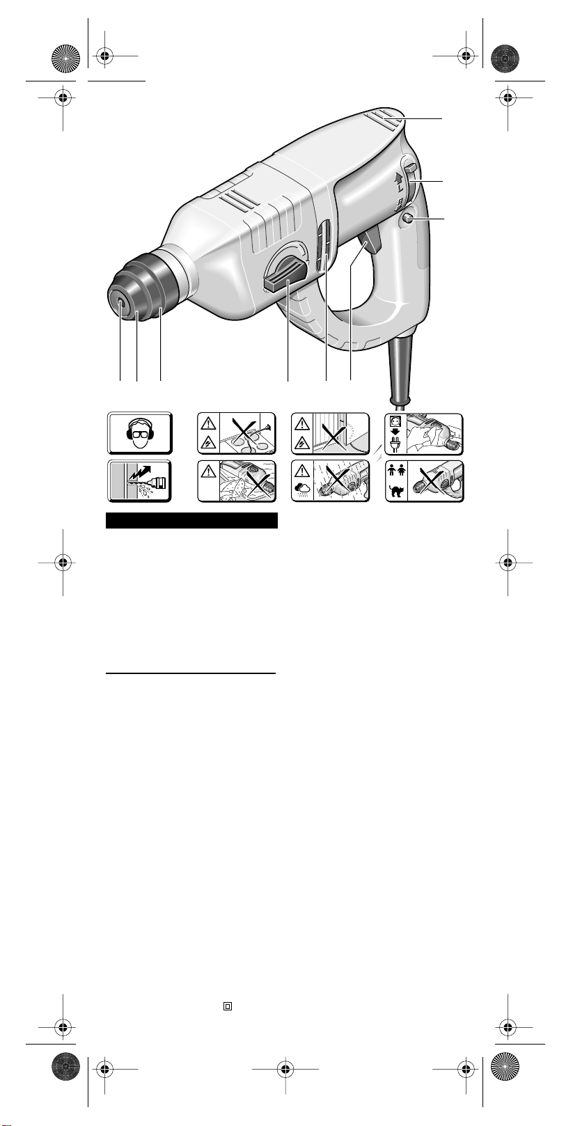
Mise en Marche/Arret
Enfoncer, respectivement: relâcher,
l’interrupteur Marche/Arrêt 6.
L’interrupteur Marche/Arrêt peut être
verrouillé en position « Marche » via
le cran d’arrêt 7. Pour désactiver ce
verrouillage, enfoncer brièvement
puis relâcher l’interrupteur
Marche/Arrêt 6.
Perçage - Perçage avec
percussion
Pour effectuer un perçage sans per-
cussion, mettre le commutateur 4 sur
la position .
Pour effectuer un perçage avec per-
cussion, mettre le commutateur sur
la position . Le mieux est de com-
muter à l’arrêt total de la machine.
Après avoir actionné l’interrupteur
Marche/Arrêt 6 ou lors du démar-
rage de la machine, l’engrenage
s’enclenche dans la position sélec-
tionnée préalablement.
Remarque: Lorsqu’un foret est
monté sur la broche, le fait d’utiliser
la rotation à gauche endommage le
foret.
Pour les travaux de perçage en
frappe, utiliser exclusivement des
forets carbure avec queue SDS-
Plus. Il n’est pas possible d’utiliser
des forets à pierre à queue cylindri-
que, comme on les trouve dans le
commerce, avec l’adaptateur 9 et le
mandrin de perçage habituel en tra-
vaillant avec le mécanisme de frappe
pneumatique.
Réglage de la vitesse de rotation
A l’aide de l’interrup-
teur Marche/
Arrêt 6, il est possi-
ble de choisir entre
deux vitesses de ro-
tation différentes.
Pour démarrer le perçage, appuyer
légèrement sur l’interrupteur
Marche/Arrêt 6 (vitesse de rotation
pour centrage). Pour disposer de
toute la puissance de la perceuse,
appuyer à fond sur l’interrupteur
Marche/Arrêt 6.
Commutation du sens de rotation
Le commutateur de
sens de rotation 8 ne
doit être actionné
que lorsque la ma-
chine est à l’arrêt
complet!
Saisir le commutateur de sens de ro-
tation 8.
Rotation à droite:
Mettre le commutateur de sens de ro-
tation 8 sur la position « R ».
Rotation à gauche:
Mettre le commutateur de sens de ro-
tation 8 sur la position « L ».
Important! Appuyer chaque fois à
fond le commutateur de sens de rota-
tion 8, c’est-à-dire veiller à ce qu’il
s’encliquette de façon perceptible.
Lorsque le commutateur de sens
de rotation 8 a été mis sur une po-
sition intermédiaire entre « R »
(rotation à droite) et « L » (rotation
à gauche), l’appareil ne se met pas
en marche.
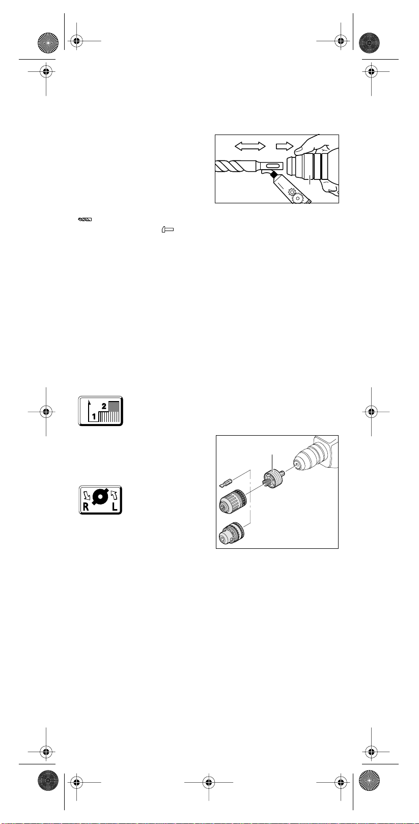
Mise en place/Retrait de l’outil
C’est le dispositif de fixation de
l’outil 1 qui effectue le serrage de
l’outil de perçage sans qu’une clé de
mandrin soit nécessaire.
Mise en place de l’outil
• Toujours extraire la fiche du cor-
don d’alimentation modulaire
hors de la prise électrique avant
d’entreprendre une quelconque
intervention sur l’appareil lui-
même.
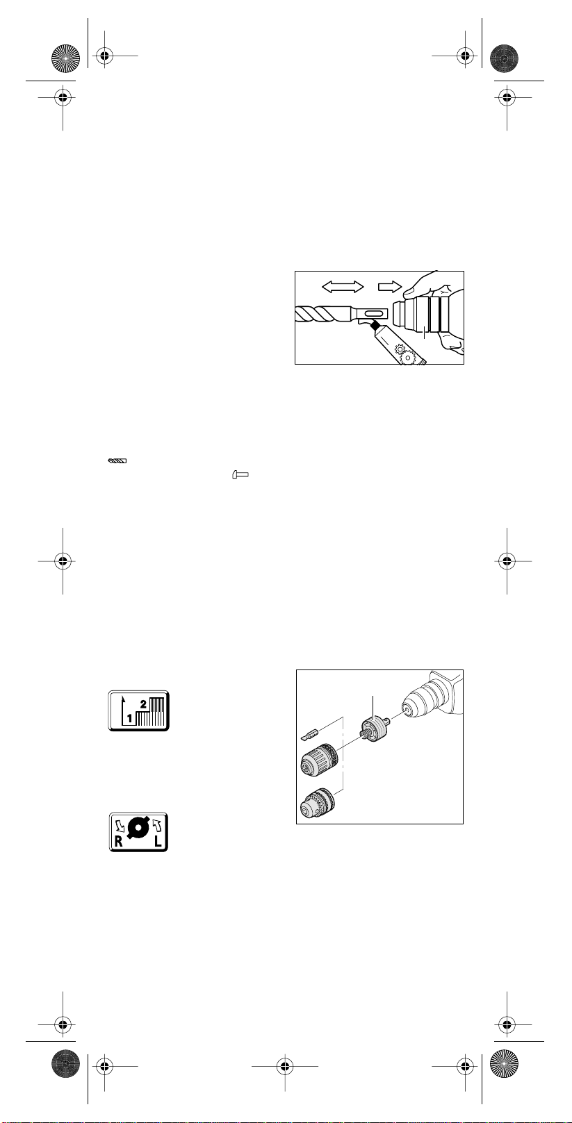
Nettoyer puis graisser légèrement la
queue de l’outil.
Repousser la bague de ver-
rouillage 3 vers l’arrière. Introduire
l’outil dans la fixation tout en impri-
mant à l’outil un mouvement de rota-
tion selon son axe principal, jusqu’à
cequ’ilenclenche. Relâcher la bague
de verrouillage 3. Contrôler enfin que
l’outil est bien en place et parfaite-
ment maintenu.
Veiller à ne pas endommager le ca-
puchon anti-poussières 2.
Remplacer sans délai tout capu-
chon anti-poussières détérioré!
SPEED
Fett
3
PK 450 HM - D +GB+F Seite 8 Donnerstag, 24. Januar 2002 9:03 09

Retrait de l’outil
Repousser la bague de ver-
rouillage 3 vers l’arrière. Extraire
l’outil hors de la fixation.
Mandrin (accessoire)
Pour réaliser des travaux de perçage
dans le métal, le bois et les matières
plastiques au moyen d’un foret à
queue cylindrique, l’utilisateur peut
faire appel à un mandrin (de 13 mm
d’ouverture maximale), livrable en
tant qu’accessoire. Ce mandrin se
monte sur l’adaptateur 9 (acces-
soire) permettant d’utiliser le pro-
gramme d’embouts de tournevis.
L’appareil est compatible avec n’im-
porte quel mandrin conventionnel
doté d’un filetage intérieur
1/2" x 20 UNF (de 13 mm d’ouver-
ture maximale).
Montage d’un mandrin
• Toujours extraire la fiche du cor-
don d’alimentation modulaire
hors de la prise électrique avant
d’entreprendre une quelconque
intervention sur l’appareil lui-
même.
Nettoyer le filetage du mandrin (ac-
cessoire) ainsi que celui de l’adapta-
teur 9 (accessoire).
Visser le mandrin de perçage sur
l’adaptateur et le serrer à fond
(30 Nm env.). Pour ce faire, serrer
l’adaptateur par exemple dans un
étau. Serrer une clé mâle pour vis à
six pans creux et avec celle-ci serrer
le mandrin de perçage. Puis ver-
rouiller l’adaptateur dans la fixation
de l’outil comme si c’était un foret.
Conseils pratiques
Ne pas percer de
trous à travers des
gaines électriques ou
des conduites d’eau
ou de gaz dissimu-
lées. Avant de percer, procéder tou-
jours à un examen de la paroi consi-
dérée.Si nécessaire,faire appelà un
détecteur de métal.
Pour percer dans les métaux, il con-
vient de toujours utiliser un foret par-
faitement affûté et en excellent état.
Pour percer la pierre ou le béton, uti-
liser des forets à mise au carbure.
Pour travailler de manière encore
plus précise dans les métaux ou
dans le bois, faire appel à un support
de preçage (accessoire).
Perçage avec percussion
Ne travailler en
mode de perçage
en frappe qu’après
avoir mis les lunet-
tes de sécurité et la
protection acousti-
que.
Ne pas exercer de pression exagé-
rée. Cela ne contribue pas à amélio-
rer les performances de la machine.
• Avant la mise en service, contrôler
si le commutateur 4 est bien encli-
queté dans la position .
Perçage dans du carrelage
Le perçage d’un carreau de faïence
doit s’effectuer à petite vitesse. N’ac-
tiver le mécanisme de frappe
qu’après avoir complètement tra-
versé le carreau de faïence.
Vissage
L’adaptateur 9 (accessoire) permet
d’utiliser les embouts de tournevis. Il
est compatible avec les embouts de
tournevis du commerce dotés d’une
queue six pans de 6,3 mm (1/4",
DIN 3126, profil C).
Les embouts de tournevis sont main-
tenus dans l’adaptateur par un res-
sort. Il convient donc de ne travailler
qu’avecdesembouts dotés d’une rai-
nure latérale.
Accouplement à glissement
Dès que l’outil de perçage se coince
ou qu’il s’accroche, l’accouplement à
glissement se déclenche.
Décharger immédiatement la ma-
chine en tirant l’outil de perçage vers
l’arrière.
Maintenir toujours la machine des
deux mains et prendre une position
stable et bien en équilibre.
Bruits et vibrations
Valeurs de mesures obtenues con-
formément à la norme européenne
EN 50 144.
Intensité de bruit: 83,5 dB (A)
Niveau de bruit: 96,5 dB (A)
Niveau d’émission acoustique
au poste de travail: 86,5 dB (A)
Les utilisateurs doivent porter une
protection acoustique.
L’accélération réelle
mesurée est 12 m/s2.
Protection de l’environnement
Kress reprend les machines rebu-
tées afin que les différentes pièces
dont elles sont constituées alimen-
tent un processus de récupération
des matières premières. Grâce à leur
conception modulaire, la séparation
des éléments récupérables des ma-
chines Kress peut s’effectuer dans
de bonnes conditions. A l’occasion
de la mise au rebut d’une machine
Kress usagée, apporter la machine
au revendeur. Il est également possi-
ble à l’utilisateur de nous l’envoyer di-
rectement.
– Sous réserves de modifications
techniques –
9
PK 450 HM - D +GB+F Seite 9 Donnerstag, 24. Januar 2002 9:03 09

CE-Konformitätserklärung
Wir erklären in alleiniger Verantwor-
tung, dass dieses Produkt mit den fol-
genden Normen oder normativen Do-
kumenten übereinstimmt:
EN50144-2-6,EN55014-1,EN55014-2,
EN 61 000-3-2, EN 61 000-3-3 ge-
mäß den Bestimmungen der Richt-
linien 73/23/EWG, 89/336/EWG,
98/37/EG.
CE Declaration of conformity
We declare under our sole responsi-
bility that this product is in conformity
with the following standards or stand-
ardization documents:
EN50144-2-6,EN55014-1,EN55014-2,
EN 61 000-3-2, EN 61 000-3-3ac-
cording to the provisions of the regu-
lations 73/23/EEC, 89/336/EEC,
98/37/EC.
CE Déclaration de conformité
Nous déclarons sous notre propre
responsabilité que ce produit est en
conformité avec les normes ou docu-
ments normalisés:
EN50144-2-6,EN55014-1,EN55014-2,
EN 61 000-3-2, EN 61 000-3-3con-
formément aux termes des régle-
mentations 73/23/CEE, 89/336/CEE,
98/37/CE.
Kress-elektrik GmbH + Co.
D-72406 Bisingen
Bisingen, im Dezember 2002
Alfred Binder, Entwicklungsleiter
Josef Leins, Leiter Qualitätssicherung
Service-Anschriften/After sales
service/Service après-vente
Bundesrepublik Deutschland:
Kress-elektrik GmbH + Co. – Elektro-
motorenfabrik – Abt. Kundendienst /
Werk II
Hechinger Straße 48
D-72406 Bisingen/Zollernalbkreis
Telefon: +49-(0)7476-874 50
Telefax: +49-(0)7476-873 75
e-mail: [email protected]
Österreich:
b + s Elektroinstallations- und
Maschinenbaugesellschaft m.b.H.
Jheringgasse 22, A-1150 Wien
Telefon: +43-(0)1-893 60 77
Telefax: +43-(0)1-893 60 16
e-mail: [email protected]
Belgie/Belgique,Nederland:
Present Handel bvba/sprl
Industriezone »Wolfstee«
Toekomstlaan 6, B-2200 Herentals
Téléphone: +32-(0)14-25 74 74
Téléfax: +32-(0)14-25 74 75
e-mail: [email protected]
France:
S.A.R.L. INDUBA
4 Rue duViaduc - B.P. 87
F-01130 Les Neyrolles
Téléphone: +33-(0)4-74 75 01 33
Téléfax: +33-(0)4-74 75 23 62
e-mail: [email protected]
Sverige:
AB Novum
Mörsaregatan 8
S-25466 Helsingborg
Phone: +46-(0)42-15 10 30
Telefax: +46-(0)42-16 16 66
e-mail: mail@abnovum.se
Norge:
Ifö Electric AS
P.O.B. 336 Alnabru
Brobekkveien 115 B, N-0614 Oslo
Phone: +47-23-37 81 10
Telefax: +47-23-37 81 20
e-mail: info@ifoelectric.no
Hellas:
D. Nikolaou & Co LTD.
Leonidoy 6, GR-17343 Athens
Phone: +30-1-975 37 57
Telefax: +30-1-973 74 23
e-mail: [email protected]
Espana:
Apolo fijaciones y herramientas, s.l.
Garrotxa Naves 10-22
Polig. Ind. Pla. de la Bruguera
E-08211 Castellar del Vallés
(Barcelona)
Telefono:+34-93-747 33 35
Telefax: +34-93-747 33 37
e-mail: [email protected]
Schweiz:
CEKA Elektrowerkzeuge AG + Co. KG.
Industriestraße 2
CH-9630 Wattwil
Telefon: +41-(0)71-987 40 40
Telefax: +41-(0)71-987 40 41
e-mail: [email protected]
Italia:
Hodara Utensili S.p.A.
Viale Lombardia, 16
I-20090 Buccinasco (Milano)
Telefon: +39-02-48 84 25 97
Telefax: +39-02-48 84 27 75
e-mail: info@hodara.it
Danmark:
Ryttergaard Vaerktoj A/S
Postbox 118, Rødovrevej 151
DK-2610 Rødovre
Telefon: +45-36 70 65 55
Telefax: +45-36 41 44 72
e-mail: [email protected]
Suomi:
Tecalemit
Hankasuontie 13, P.O. Box 78
FIN-00391 Helsinki
Phone: +358(0)9-54 77 01
Telefax: +358(0)9-547 17 79
e-mail: [email protected]
Great Britain:
N & J Tools Ltd.
Westcross Centre, 15 Shield Drive
Brentford TW8 9EX
Phone: +44-(0)208-560 0885
Telefax: +44-(0)208-847 0790
e-mail: njtoolsbrentford@btopenworld.com
Portugal:
Sarraipa S.A.
Máquinas e Equipamentos Industriais
Rua das Flores
Carreira d´Agua
Zona Industrial da Barosa
PT-2400 Leiria
Phone: +351-(2)44-81 90 60
Telefax: +351-(2)44-81 90 69
e-mail: [email protected]
Deutsch
English
Français
PK 450 HM - D +GB+F Seite 10 Donnerstag, 24. Januar 2002 9:03 09
Table of contents
Languages:
Other KRESS Tools manuals