krispol STARCUS ONE User manual

STEROWANIE
Możliwość sterowania 1 napędem serii M lub E
1. INFORMACJE TECHNICZNE
2. OPIS URZĄDZENIA
Zasięg podawany przez producenta jest wartością zmienną,zależną od warunków panujących
w środowisku, w którym urządzenie pracuje. Wpływ na zasięg mają takie czynniki jak:
konstrukcja budynku, zakłócenia sygnału generowane przez inne urządzenia itp.
STARCUS WIRELESS
RECEIVER
PAMIĘĆ
Do 10 nadajników
MOC WYJŚCIOWA
200 W
ZASIĘG
Do 25 metrów w pomieszczeniach
NAPIĘCIE ZASILANIA / NA WYJŚCIU
230 V / 50 Hz
WYMIARY
50 x 45 x 23 mm
CZĘSTOTLIWOŚĆ
433,92 MHz
STOPIEŃ OCHRONY
IP 20
INSTRUKCJA OBSŁUGI
STARCUS WIRELESS RECEIVER v2.0
WAŻNE!
KOSTKA PRZYŁĄCZENIOWA
ANTENA
PRZYCISK PROGRAMOWANIA DIODA LED
FUNKCJE PRZYCISKU PROGRAMOWANIA:
1. Krótkie wciśnięcie przycisku programowania przez ok. 1 s. steruje napędem krok po kroku.
Funkcja aktywna jest po zaprogramowaniu położeń krańcowych.
2. Wciśnięcie przycisku programowania przez 2 s. wprowadza centralkę w tryb programowania nadajnika.
3. Wciśnięcie przycisku programowania przez 6 s. włącza funkcję blokowania sygnału radiowego.
Aby wyłączyć funkcję, należy wcisnąć na krótko przycisk programowania lub odłączyć zasilanie centralki.
4. Wciśnięcie przycisku programowania przez 10 s. zmienia kierunki pracy napędu.
5. Wciśnięcie przycisku programowania przez 14 s. kasuje pamięć centralki przywraca ustawienia fabryczne.
L N N C D U
↑
↑
PL

3. MONTAŻ
4. PROGRAMOWANIE PIERWSZEGO NADAJNIKA
Optymalne odległości montażowe:
a) Minimalna odległość centralki od podłoża > 1,5 m
b) Minimalna odległość centralki od sufitu i ścian > 0,3 m
c) Minimalna odległość między centralkami > 0,2 m
Dłuższa niż 10 sekund przerwa, między kolejnymi wciśnięciami przycisku, spowoduje automatyczne
wyjście z trybu programowania, bez zapisania wprowadzonych zmian.
dół
góra
niebieski
żółty/zielony
zasilanie:
230 V / 50 Hz
napęd:
230 V / 50 Hz
L – przewód fazowy (zasilanie)
N – przewód neutralny (zasilanie)
N – przewód neutralny (napęd)
– kierunek góra (napęd)
– kierunek dół (napęd)
C – COM
D – kierunek dół (przełącznik)
U – kierunek góra (przełącznik)
WAŻNE!
Montaż powinien być przeprowadzony przez osoby posiadające odpowiednie uprawnienia SEP.
Urządzenie przeznaczone jest do montażu w miejscach, wktórych nie będzie narażone na bezpośrednie
działanie warunków atmosferycznych. Urządzenie powinno być zamontowane zgodnie ze sztuką oraz
przepisami i normami obowiązującymi w Polsce i na terenie UE. Przewody łączące odbiornik energii
elektrycznej ze źródłem zasilania powinny być zabezpieczone przed skutkami przeciążenia i zwarcia
urządzeniami zabezpieczającymi, które samoczynnie wyłączą zasilanie. Urządzenie powinno być zasilane
za pośrednictwem osobnej linii, jedynie z sieci spełniającej odpowiednie normy.
x3
Nadajnik został
zaprogramowany
Wyłączamy zasilanie
i ponownie włączamy.
Roleta wykona krótkie
ruchy góra/dół. Dioda
LED mignie raz.
Wciskamy
i przytrzymujemy
przez 2 sekundy
przycisk STOP
na pilocie.
Roleta wykona dwa krótkie ruchy
góra/dół. Dioda LED zamiga
trzy razy.

5. ZMIANA KIERUNKU PRACY NAPĘDU
6. PROGRAMOWANIE KOLEJNEGO NADAJNIKA
Zamiana kierunku pracy następuje wtedy, jeśli klawiszem DÓŁ podnosimy roletę, aklawiszem GÓRA ją opuszczamy.
1. Centralka może być sterowana maksymalnie 10 nadajnikami.
2. Dłuższa niż 10 sekund przerwa, między kolejnymi wciśnięciami przycisku, spowoduje automatyczne
wyjście z trybu programowania bez wprowadzonych zmian.
SPOSÓB NR 1:
SPOSÓB NR 2:
Kierunek pracy
napędu został
zmieniony
Kierunek pracy
napędu został
zmieniony
Jednocześnie wciskamy
iprzytrzymujemy przez 2 s.
przyciski GÓRA orazDÓŁ.
Wciskamy iprzytrzymujemy
przez 10 s. przycisk
programowania na centralce.
Roleta wykona
krótkie ruchy góra/dół.
Dioda LED zamiga
trzy razy.
Roleta wykona krótkie
ruchy góra/dół.
A
A A
B
Wciskamy przycisk
programowania P2
na pilocie A.
Roleta wykona
krótkie ruchy góra/dół.
Dioda LED mignie raz.
Roleta wykona dwa krótkie
ruchy góra/dół. Dioda LED
zamiga trzy razy.
Pilot B został
zaprogramowany.
Wciskamy przycisk
programowania P2
na pilocie A.
B
x3
Wyłączamy zasilanie
i ponownie włączamy.
Wyłączamy zasilanie
i ponownie włączamy.
B
Roleta wykona
krótkie ruchy góra/dół.
Dioda LED mignie raz.
Wciskamy przycisk
programowania P2
na pilocie B.
Wyłączamy zasilanie
i ponownie włączamy.

Wciskamy
przycisk STOP.
Wciskamy
przycisk STOP.
Wciskamy
przycisk STOP.
7. PROGRAMOWANIE POZYCJI KOMFORT
8. USUWANIE POZYCJI KOMFORT
9. STEROWANIE PROCENTOWE
1. Po ustawieniu górnego i dolnego położenia krańcowego, możliwe jest ustawienie trzeciej pozycji
(ulubionej) pomiędzy tymi położeniami.
2. Przytrzymanie przyciskuSTOP przez 3 s. powoduje ustawienie rolety w trzecim położeniu krańcowym.
Ustawiamy
roletę w trzecim
położeniu krańcowym.
Wciskamy przycisk
programowania P2.
Wciskamy przycisk
programowania P2.
Roleta wykona krótkie ruchy
góra/dół. Dioda LED mignie raz.
Roleta wykona krótkie ruchy
góra/dół. Dioda LED mignie raz.
Roleta wykona dwa krótkie ruchy
góra/dół. Dioda LED mignie trzy razy.
Roleta wykona krótkie ruchy góra/dół.
Dioda LED mignie raz.
x3
Pozycja komfort
zaprogramowana
Pozycja komfort
została usunięta
Wciskamy
przycisk STOP.
Roleta wykona krótkie ruchy
góra/dół. Dioda LED mignie raz.
Wciskamy
przycisk STOP.
Roleta wykona krótkie ruchy
góra/dół. Dioda LED mignie raz.
Wyłączamy zasilanie
i ponownie włączamy.
Wyłączamy zasilanie
i ponownie włączamy.
Wciskamy przycisk
programowania P2.
Roleta wykona
krótkie ruchy góra/dół.
Dioda LED mignie raz.
Roleta wykona
krótkie ruchy góra/dół.
Dioda LED mignie raz.
Wyłączamy
zasilanie
i ponownie
włączamy.
Wciskamy
przycisk DÓŁ.
Jeżeli roleta wykona dwie sekwencje krótkich ruchów
góra/dół, dioda LED zamiga trzy razy, oznacza to,
że u sterowanie procentowe zostało włączone.
Jeżeli roleta wykona jedną sekwencje krótkich ruchów
góra/dół, a dioda LED świeci na stałe sterowanie
procentowe zostało wyłączone.
BA

Wciskamy
przycisk DÓŁ.
10. USUWANIE POŁOŻEŃ KRAŃCOWYCH
11. USUWANIE JEDNEGO NADAJNIKA
12. USUWANIE WSZYSTKICH NADAJNIKÓW
Wciskamy przycisk
programowania P2.
Wciskamy przycisk
programowania P2.
Roleta wykona krótkie ruchy
góra/dół. Dioda LED mignie raz.
Roleta wykona krótkie ruchy
góra/dół. Dioda LED mignie raz.
Położenia
krańcowe
zostały usunięte
Pilot B został
usunięty
Wszystkie nadajniki
zostały usunięte
Wykonanie poniższej procedury powoduje usunięcie położeń krańcowych centralki razem z pozycją komfort.
Roleta wykona dwa krótkie ruchy
góra/dół. Dioda LED mignie trzy razy.
x3
A
A A
B
B
Wciskamy przycisk
programowania P2
na pilocie A.
Wciskamy przycisk
programowania P2.
Roleta wykona
krótkie ruchy góra/dół.
Dioda LED mignie raz.
Roleta wykona
krótkie ruchy góra/dół.
Dioda LED mignie raz.
Roleta wykona dwa
krótkie ruchy góra/dół.
Dioda LED zamiga trzy razy.
Roleta wykona dwa krótkie ruchy góra/dół.
Dioda LED zamiga trzy razy.
Roleta wykona
krótkie ruchy góra/dół.
Dioda LED mignie raz.
Roleta wykona
krótkie ruchy góra/dół.
Dioda LED mignie raz.
Wciskamy przycisk
programowania P2
na pilocie A.
Wciskamy przycisk
programowania
P2 na pilocie B.
Wciskamy przycisk
programowania P2.
x3
x3
Wciskamy
przycisk STOP.
Roleta wykona krótkie ruchy
góra/dół. Dioda LED mignie raz.
Wyłączamy
zasilanie
i ponownie
włączamy.
Wyłączamy zasilanie
i ponownie włączamy.
Wyłączamy zasilanie
i ponownie włączamy.

14. WŁĄCZENIE FUNKCJI PRZECIĄŻENIA
13. REAKCJA NAPĘDU NA PRZECIĄŻENIE
15. REGULACJA CZUŁOŚCI PRZECIĄŻENIA
Wciskamy przycisk
programowania P2.
Wciskamy przycisk
programowania P2.
Wciskamy przycisk
programowania P2.
Roleta wykona
krótkie ruchy góra/dół.
Dioda LED mignie raz.
Roleta wykona
krótkie ruchy góra/dół.
Dioda LED mignie raz.
Roleta wykona
krótkie ruchy góra/dół.
Dioda LED mignie raz.
Roleta wykona
krótkie ruchy góra/dół.
Dioda LED mignie raz.
Roleta wykona
krótkie ruchy góra/dół.
Dioda LED mignie raz.
Roleta wykona
krótkie ruchy góra/dół.
Dioda LED mignie raz.
Wciskamy
przycisk STOP.
Wciskamy
przycisk DÓŁ.
Wciskamy
przycisk STOP.
Wciskamy
przycisk DÓŁ.
Wciskamy
przycisk DÓŁ.
Wciskamy
przycisk GÓRA.
Jeżeli roleta wykona dwa krótkie ruchy góra/dół,
dioda LED zamiga trzy razy, oznacza to,
że uruchomiona jest funkcja przeciążenia.
Jeżeli roleta wykona dwa krótkie ruchy
góra/dół, dioda LED zamiga trzy razy,
oznacza to,że uruchomiona jest reakcja 1:
po wykryciu przeszkody napęd zatrzyma się.
Dioda LED zamiga, a ilość mignięć diody (1-6) będzie
oznaczała ustawiony stopień czułości.
Jeżeli roleta wykona krótkie ruchy góra/dół, dioda LED
mignie raz, oznacza to, że wyłączono funkcję przeciążenia.
Jeżeli roleta wykona krótkie ruchy góra/dół,dioda LED
mignie raz, oznacza to, że uruchomiona jest reakcja 2:
po wykryciu przeszkody napęd wykona krótki ruch
w przeciwnym kierunku.
Funkcja przeciążenia nie jest aktywna przez 2 sekundy po uruchomieniu napędu. Domyślnie funkcja
przeciążenia jest wyłączona.
1. Centralka posiada sześciostopniową skalę regulacji przeciążenia. Stopień 1 oznacza najbardziej czułe
przeciążenie, a stopień 6 najmniej czułe przeciążenie.
2. Domyślnie ustawiony jest drugi stopień czułości.
B
B
B
B
A
A
A
A
A
A
Wyłączamy
zasilanie
i ponownie
włączamy.
Wyłączamy
zasilanie
i ponownie
włączamy.
Wyłączamy
zasilanie
i ponownie
włączamy.

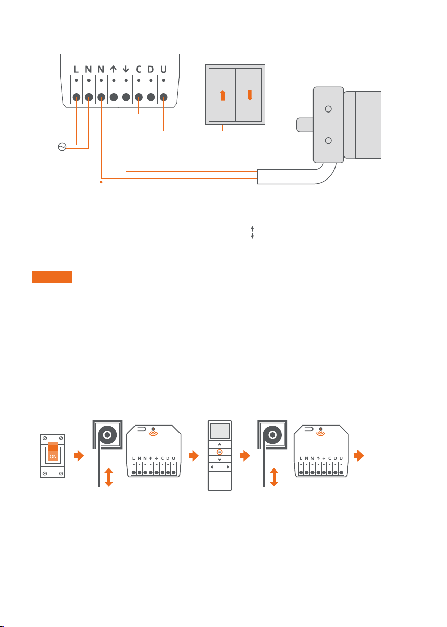
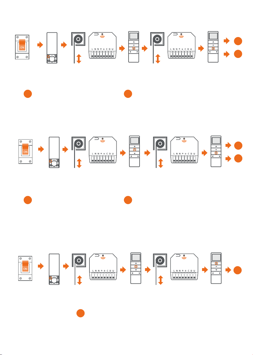
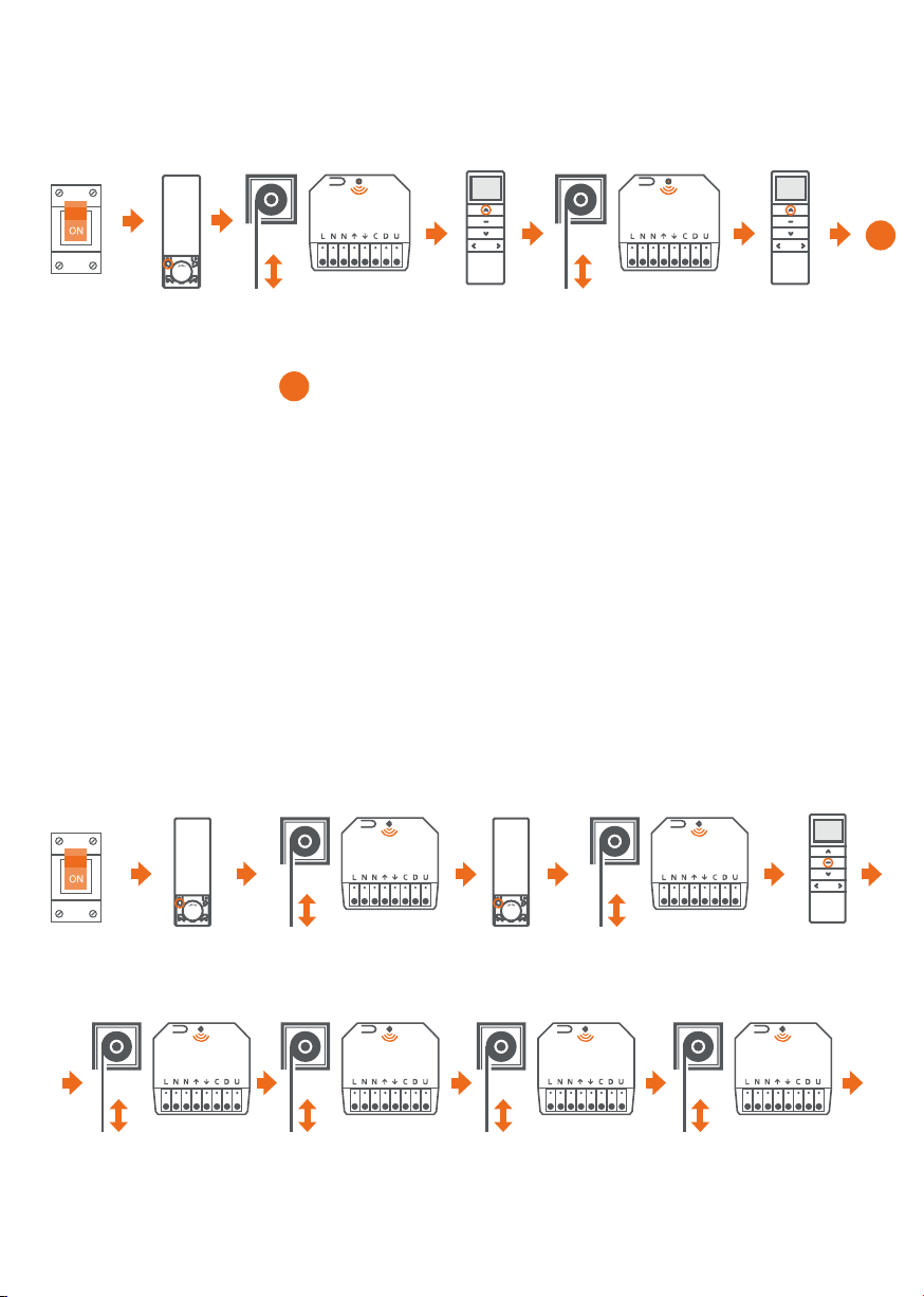
16. AKTYWACJA TRYBU IMPULSOWEGO
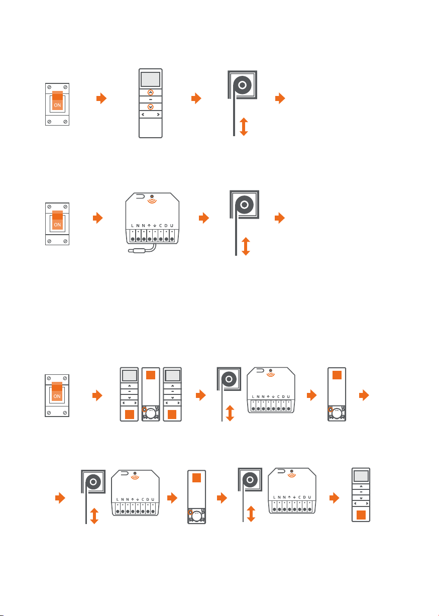
17. KONFIGURACJA PRZEŁĄCZNIKA
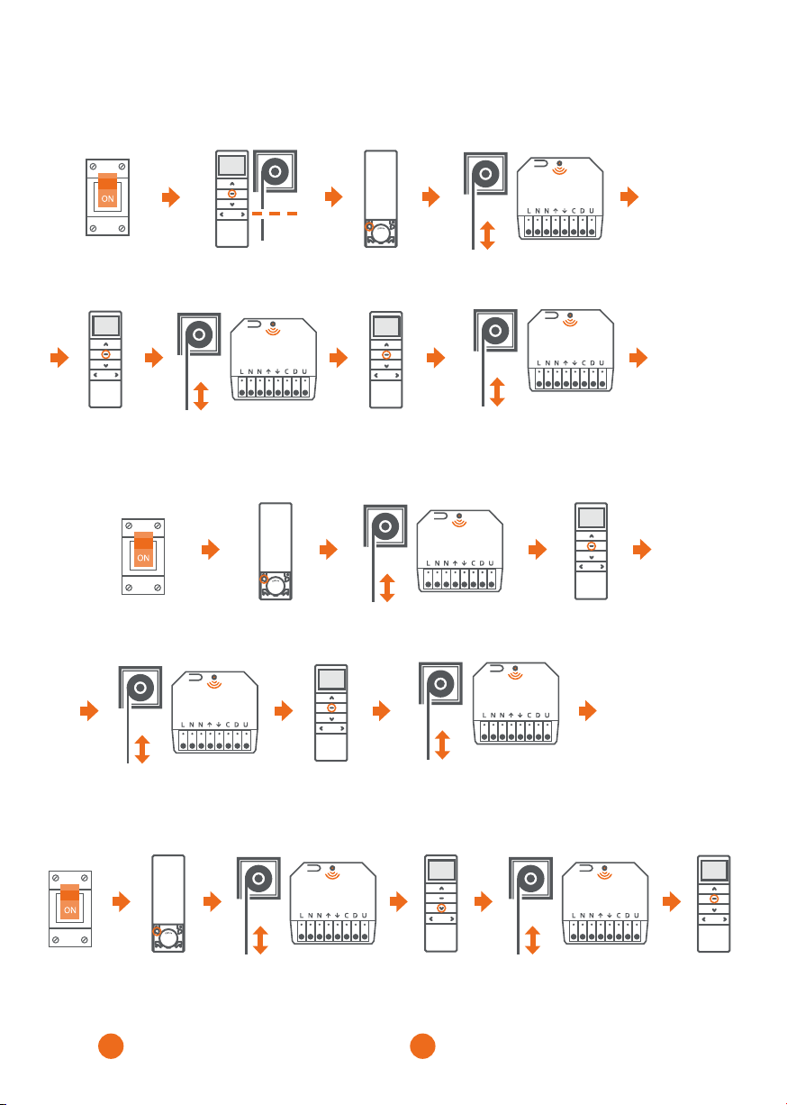
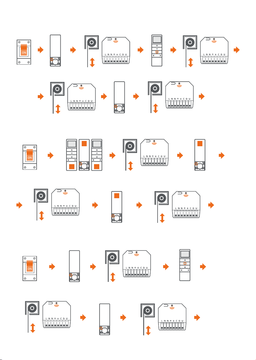
18. ZMIANA TRYBÓW PRACY PRZEŁĄCZNIKA
Wciskamy przycisk
programowania P2.
Wciskamy przycisk
programowania P2.
Wciskamy przycisk
programowania P2.
Roleta wykona
krótkie ruchy góra/dół.
Dioda LED mignie raz.
Roleta wykona
krótkie ruchy góra/dół.
Dioda LED mignie raz.
Roleta wykona
krótkie ruchy góra/dół.
Dioda LED mignie raz.
Roleta wykona
krótkie ruchy góra/dół.
Dioda LED mignie raz.
Jeżeli roleta wykona
krótkie ruchy góra/dół,
dioda LED mignie raz
- ustawiony jest tryb I.
Jeżeli roleta wykona dwa
krótkie ruchy góra/dół,
dioda LED mignie dwa razy
- ustawiony jest tryb II.
Jeżeli roleta wykona trzy
krótkie ruchy góra/dół,
dioda LED mignie trzy razy
- ustawiony jest tryb III.
Jeżeli roleta wykona cztery
krótkie ruchy góra/dół,
dioda LED mignie cztery razy
- ustawiony jest tryb IV.
Wciskamy
przycisk GÓRA.
Wciskamy
przycisk DÓŁ.
Wciskamy
przycisk STOP.
Jeżeli roleta wykona krótkie ruchy góra/dół, dioda LED
mignie raz, tryb impulsowy jest włączony.
1. Aktywacja trybu impulsowego możliwa jest po zaprogramowaniu położeń krańcowych centralki.
2. Gdy tryb impulsowy jest włączony, po jednokrotnym wciśnięciu przycisku kierunku na pilocie, napęd
wykona krótki ruch.
Odbiornik może pracować w jednym z czterech trybów przełącznika.
I TRYB – PRZEŁĄCZNIK ŻALUZJOWY ASTABILNY
Krótkie wciśnięcie klawisza GÓRA lub DÓŁ powoduje ruch rolety. Ponowne wciśnięcie klawisza
powoduje jej zatrzymanie.
II TRYB – PRZEŁĄCZNIK ŻALUZJOWY STABILNY
Wciśnięcie klawisza GÓRA lub DÓŁ powoduje ruch rolety. Zwolnienie klawisza powoduje jej zatrzymanie.
III TRYB – PRZEŁĄCZNIK ASTABILNY
Krótkie wciśnięcie klawisza GÓRA lub DÓŁ powoduje ruch rolety. Jednoczesne wciśnięcie klawiszy
GÓRA i DÓŁ powoduje jej zatrzymanie. W trybie impulsowym krótkie wciśnięcie klawisza GÓRA lub DÓŁ
powoduje krótki ruch rolety. Przytrzymanie klawisza GÓRA lub DÓŁ powyżej 2 sekund powoduje ciągły
ruch rolety, ponowne wciśnięcie klawisza zatrzymuje ją.
IV TRYB – PRZEŁĄCZNIK IMPULSOWY
W tym trybie przełącznik działa w trybie krok po kroku. Wciśnięcie klawisza powoduje ruch rolety w górę,
ponowne jego wciśnięcie zatrzymuje roletę, akolejne wciśnięcie klawisza powoduje ruch rolety w kierunku DÓŁ.
A
A
x2
x2
x3
x3
x4
x4
Wyłączamy
zasilanie
i ponownie
włączamy.
Wyłączamy
zasilanie
i ponownie
włączamy.

OCHRONA ŚRODOWISKA
Niniejsze urządzenie zostało oznakowane zgodnie z Dyrektywą WEEE (2002/96/EC), dotyczącą
zużytego sprzętu elektrycznego i elektronicznego. Zapewniając prawidłowe złomowanie przyczyniają
się Państwo do ograniczenia ryzyka wystąpienia negatywnego wpływu produktu na środowisko
i zdrowie ludzi, które mogłoby zaistnieć w przypadku niewłaściwej utylizacji urządzenia.
Symbol umieszczony na produkcie lub dołączonych do niego dokumentach oznacza, że niniejszy
produkt nie jest klasyfikowany jako odpad z gospodarstwa domowego. Urządzenie należy oddać
do odpowiedniego punktu utylizacji odpadów w celu recyklingu. Aby uzyskać dodatkowe informacje
dotyczące recyklingu niniejszego produktu należy skontaktować się z przedstawicielem władz lokalnych,
dostawcą usług utylizacji odpadów lub sklepem, gdzie nabyto produkt.

CONTROL
Control option with1 drive of M or E series
1. TECHNICAL DATA
2. DEVICE DESCRIPTION
e range declared by the manufacturer is a variable value, depending on the environmental conditions
of the device operation. e range is influenced by factors such as: building structure, signal interference
from other devices, etc.
STARCUS WIRELESS
RECEIVER
MEMORY
Up to 10 transmitters
OUTPUT POWER
200 W
RANGE
Up to 25 meters indoors
SUPPLY / OUTPUT VOLTAGE
230 V / 50 Hz
DIMENSIONS
50 x 45 x 23 mm
FREQUENCY
433,92 MHz
IP RATING
IP 20
INSTRUCTION MANUAL OF
STARCUS WIRELESS RECEIVER v2.0
IMPORTANT!
CONNECTOR BLOCK
ANTENNA
PROGRAMMING BUTTON LED
PROGRAMMING BUTTON FUNCTIONS:
1. Briefly pressing the programming button for approx. 1 second controls the drive unit step by step.
e function is active after programming the end positions.
2. Pressing the programming button for 2 seconds switches the control unit into the transmitter programming mode.
3. Pressing the programming button for 6 seconds activates the radio signal blocking function.
In order to disable the function, briefly press the programming button or disconnect the control unit power supply.
4. Pressing the programming button for 10 seconds changes the direction of the drive's operation.
5. Pressing the programming button for 14 seconds deletes the memory of the control unit and restores
the factory settings.
L N N C D U
↑
↑
EN

3. INSTALLATION
4. PROGRAMMING THE FIRST TRANSMITTER
Optimum distances for mounting:
a) e minimum distance of the control unit from the base > 1.5 m
b) e minimum distance of the control unit from the ceiling
and walls > 0.3 m
c) Minimum distance between units> 0.2 m
A pause between successive button presses longer than 10 seconds will result in automatic quitting
the programming mode, without saving any changes.
down
up
blue
Yellow/green
230 V / 50 Hz
drive:
230 V / 50 Hz
L – phase conductor (power supply)
N – neutral wire (power supply)
N – neutral wire (drive)
– UP direction (drive)
– DOWN direction (drive)
C – COM
D – UP direction (switch)
U – DOWN direction (switch)
IMPORTANT!
Installation should be performed by persons with appropriate SEP qualifications.
e device is designed for installation in places not exposed to direct weather conditions.
e device should be installed in accordance with industry practises, Polish and EU regulations
and standards in force. Cables connecting the electric energy receiver with the power source should
be protected against overload and short circuit with safety devices automatically disconnecting power.
e device should be powered via a separate line, only from a grid that meets the relevant standards.
x3
e transmitter
has now been
programmed
Turn off the power
and turn it on again.
e roller shutter makes
short up/down movements.
e LED will flash once.
Press and hold
the STOP button
on the remote
control for
2 seconds.
e roller shutter makes two short
up/down movements. e LED will
flash three times.

5. CHANGE OF THE DRIVE OPERATION DIRECTION
6. PROGRAMMING OF ANOTHER TRANSMITTER
e direction of operation can be changed with the DOWN button in order to raise the roller shutter,
or with the UP button in order to lower it.
1. e control unit can be controlled by a maximum of 10 transmitters.
2. A pause between successive button presses longer than 10 seconds will result
in automatic quitting the programming mode without saving changes.
METHOD NO. 1:
METHOD NO. 2:
e operating
direction of the drive
has been changed
e operating
direction of the
drive has been
changed
Press and hold the UP
and DOWN button for
2 seconds.
Press and hold the programming button
on the control unit for 10 seconds.
e roller shutter makes
short up/down movements.
e LED will flash three times.
e roller shutter makes short
up/down movements
A
A A
B
Press the P2 programming
button on the A remote control.
e roller shutter makes short
up/down movements. e LED
will flash once.
e roller shutter makes two
short up/down movements.
e LED will flash three times.
B remote control
has been programmed.
Press the P2 programming
button on the A remote control.
B
x3
Turn off the power
and turn it on again.
Turn off the power
and turn it on again.
B
e roller shutter makes short
up/down movements. e LED
will flash once.
Press the P2
programming button
on the B remote control.
Turn off the power
and turn it on again.

Press the
STOP button.
Press the
STOP button.
Press the
STOP button.
7. PROGRAMMING THE COMFORT POSITION
8. DELETING THE COMFORT POSITION
9. CONTROL WITH PERCENTAGE FUNCTION
1. After setting the up and down end positions, it is possible to set a third (favourite) position in between.
2. Holding the STOP button for 3 seconds sets the roller shutter in the third end position.
Set the roller shutter to
the third end position.
Press the P2
programming button.
Press the P2
programming button.
e roller shutter makes short up/down
movements. e LED will flash once.
e roller shutter makes short
up/down movements. e LED
will flash once.
e roller shutter makes two short
up/down movements. e LED will flash
three times.
e roller shutter makes short up/down
movements. e LED will flash once.
x3
e Comfort
position has
been programmed.
e Comfort
position has
been deleted
Press the
STOP button.
e roller shutter makes short
up/down movements.
e LED will flash once.
Press the
STOP button.
e roller shutter makes short
up/down movements.
e LED will flash once.
Turn off the power
and turn it on again.
Turn off the power
and turn it on again.
Press the P2
programming button.
e roller shutter makes
short up/down movements.
e LED will flash once.
e roller shutter makes short
up/down movements.
e LED will flash once.
Turn off the
power and turn
it on again.
Press the
DOWN button.
If the roller shutter performs two sequences
of short up / down movements, the LED flashes
three times; it means that the percentage control
has been turned on.
If the roller shutter performs one sequence
of short up/down movements and the LED
is permanently on, it means the percentage
control has been turned off.
BA

Press the
DOWN button.
10. DELETING END POSITIONS
11. DELETING ONE TRANSMITTER
12. DELETING ALL TRANSMITTERS
Press the P2
programming button.
Press the P2
programming button.
e roller shutter makes short up/down
movements. e LED will flash once.
e roller shutter makes short up/down
movements. e LED will flash once.
End positions
have been
deleted
B remote
control has
been deleted
All transmitters
have been deleted.
e following procedure is to remove the end positions of the control unit together with the Comfort position.
e roller shutter makes two short
up/down movements. e LED will
flash three times.
x3
A
A A
B
B
Press the P2 programming
button on the A remote control.
Press the P2
programming button.
e roller shutter makes short
up/down movements. e LED
will flash once.
e roller shutter makes short up/down
movements. e LED will flash once.
e roller shutter makes two short up/down
movements. e LED will flash three times.
e roller shutter makes two short up/down
movements. e LED will flash three times.
e roller shutter makes short up/down
movements. e LED will flash once.
e roller shutter makes short
up/down movements. e LED
will flash once.
Press the P2 programming
button on the A remote control.
Press the P2 programming
button on the B remote control.
Press the P2
programming button.
x3
x3
Press the
STOP button.
e roller shutter makes short
up/down movements. e LED
will flash once.
Turn off the
power and
turn it on again.
Turn off the power
and turn it on again.
Turn off the power
and turn it on again.

14. ACTIVATION OF THE OVERLOAD FUNCTION
13. DRIVE REACTION TO OVERLOAD
15. SENSITIVITY OF OVERLOAD ADJUSTMENT
Press the P2
programming button.
Press the P2
programming button.
Press the P2
programming button.
e roller shutter makes
short up/down movements.
e LED will flash once.
e roller shutter makes
short up/down movements.
e LED will flash once.
e roller shutter makes
short up/down movements.
e LED will flash once.
e roller shutter makes short
up/down movements. e LED
will flash once.
e roller shutter makes
short up/down movements.
e LED will flash once.
e roller shutter makes
short up/down movements.
e LED will flash once.
Press the
STOP button.
Press the
DOWN button.
Press the
STOP button.
Press the
DOWN button.
Press the
DOWN button.
Press the
UP button.
If the roller shutter makes two short up/down
movements, the LED will flash three times; this
means the overload functions has been activated.
If the roller shutter makes two short up/down
movements, the LED will flash three times;
this means that response 1 is activated: after
having detected any obstacles, the drive stops.
e LED blinks and the number of LED flashes (1-6)
which indicates the set sensitivity level.
If the roller shutter makes short up/down movements,
the LED will flash once; this means the overload functions
has been disabled.
If the roller shutter makes short up/down movements,
LED will flash once; it means that response 2 is activated:
after having detected any obstacles, the drive will make
a short movement in the opposite direction.
e overload function is not active for 2 seconds after the drive has started. By default, the overload function is disabled.
1. e switchboard has a six-step overload adjustment scale. Level 1 is the most sensitive overload
and level 6 the least sensitive overload.
2. e second sensitivity level is set by default.
B
B
B
B
A
A
A
A
A
A
Turn off the
power and turn
it on again.
Turn off the
power and turn
it on again.
Turn off the
power and turn
it on again.

16. ACTIVATION OF IMPULSE MODE
17. SWITCH CONFIGURATION
18. CHANGING THE SWITCH OPERATING MODES
Press the P2
programming button.
Press the P2
programming button.
Press the P2
programming button.
e roller shutter makes
short up/down movements.
e LED will flash once.
e roller shutter makes
short up/down movements.
e LED will flash once.
e roller shutter makes
short up/down movements.
e LED will flash once.
e roller shutter makes
short up/down movements.
e LED will flash once.
If the roller shutter makes short
up/down movements and the
LED flashes once - mode I has
been set.
If the roller shutter makes short
up/down movements and the
LED flashes twice - mode II
has been set.
If the roller shutter makes short
up/down movements and the
LED flashes three times - mode
III has been set.
If the roller shutter makes short
up/down movements and the LED
flashes four times - mode IV has
been set.
Press the
UP button.
Press the
DOWN button.
Press the
STOP button.
If the roller shutter makes short up/down movements,
the LED flashes once which means the impulse mode is on.
1. Activation of the impulse mode is possible after programming the end positions of the control unit.
2. When the impulse mode is on, the drive will make a short movement after pressing the direction
button on the remote control once.
e receiver can work in one of the four switch modes.
I MODE - ASTABLE SHUTTER SWITCH
A short press of the UP or DOWN button causes the roller shutter to move. Pressing the button
again stops the movement.
II MODE - STABLE SHUTTER SWITCH
Pressing the UP or DOWN button causes the roller shutter to move. Releasing the button stops the movement.
III MODE - ASTABLE SWITCH
A short press of the UP or DOWN button causes the roller shutter to move. Pressing the UP and DOWN
buttons simultaneously will stop the movement. In the impulse mode, a short press of the UP or DOWN
button causes a short movement of the roller shutter. Holding the UP or DOWN button for more than
2 seconds causes the roller shutter to move continuously; pressing the button again stops the movement.
IV MODE - IMPULSE SWITCH
In this mode, the switch works in step-by-step mode. Pressing the button causes the roller shutter
to move UP, pressing it again stops the roller shutter, and another pressing the button causes the roller
shutter to move DOWN.
A
A
x2
x2
x3
x3
x4
x4
Turn off the
power and turn
it on again.
Turn off the
power and turn
it on again.

ENVIRONMENTAL PROTECTION
is appliance is labelled according to the WEEE Directive (2002/96/EC) on Waste Electrical and Electronic
Equipment. By ensuring proper disposal, you contribute to reducing the risk of a negative impact of the
product on the environment and human health, which could occur in the event of inappropriate disposal
of the device.
e symbol on the product or accompanying documents means that this product is not classified as
household waste. Take the device to an applicable waste disposal point for recycling. For additional
information regarding the recycling of this product, please contact your local authority, your waste
disposal service provider, or the shop where you purchased the product.

STEUERUNG
Möglichkeit der Steuerung eines Antriebs der Serie M oder E
1. TECHNISCHE INFORMATIONEN
2. BESCHREIBUNG DES GERÄTS
Die vom Hersteller angegebene Reichweite ist ein variabler Wert, der von den Bedingungen
der Umgebung abhängt, in der das Gerät betrieben wird. Die Reichweite wird durch Faktoren
wie die Konstruktion des Gebäudes, Signalstörungen durch andere Geräte usw. beeinflusst.
STARCUS WIRELESS
RECEIVER
SPEICHER
Bis zu 10 Sender
AUSGANGSLEISTUNG
200 W
REICHWEITE
BIS ZU 25 Metern in Innenräumen
VERSORGUNGSSPANNUNG / AUSGANGSSPANNUNG
230 V / 50 Hz
ABMASSE
50 x 45 x 23 mm
HÄUFIGKEIT
433,92 MHz
SCHUTZGRAD
IP 20
BEDIENUNGSANLEITUNG
STARCUS WIRELESS RECEIVER v2.0
WICHTIG!
KOSTKA PRZYŁĄCZENIOWA
ANTENA
PRZYCISK PROGRAMOWANIA DIODA LED
FUNKTIONEN DER PROGRAMMIERTASTE:
1. Durch kurzes Drücken der Programmiertaste für ca. 1 s wird der Antrieb schrittweise gesteuert.
Die Funktion wird nach der Programmierung der Endlagen aktiviert.
2. Durch 2 Sekunden langes Drücken der Programmiertaste wird das Steuergerät in den
Programmiermodus des Senders versetzt.
3. Durch Drücken der Programmiertaste für 6 Sekunden wird die Funksignalblockierung aktiviert.
Um die Funktion zu deaktivieren, drücken Sie kurz die Programmiertaste oder unterbrechen Sie
die Stromzufuhr der Zentrale.
4. Durch 10 s langes Drücken der Programmiertaste wird die Betriebsrichtung des Antriebs geändert.
5. Durch 14 Sekunden langes Drücken der Programmiertaste wird der Speicher der Zentrale gelöscht
und die Werkseinstellungen wiederhergestellt.
L N N C D U
↑
↑
DE

3. MONTAGE
4. PROGRAMMIERUNG DES ERSTEN SENDERS
Optimale Montageabstände:
a) Minimaler Abstand der Zentrale vom Fußboden > 1,5 m
b) Minimaler Abstand der Zentrale von Decke und Wänden > 0,3 m
c) Minimaler Abstand zwischen den Zentralen > 0,2 m
Wenn zwischen zwei aufeinanderfolgenden Tastendrücken mehr als 10 Sekunden vergehen, wird der
Programmiermodus automatisch verlassen, ohne dass die vorgenommenen Änderungen gespeichert werden.
Ab
Auf
blau
gelb/grün
Stromversorgung:
230 V / 50 Hz
Antrieb:
230 V / 50 Hz
L – Phasenleiter
N – Nullleiter (Stromversorgung)
– Richtung „nach oben“ (Antrieb)
C – COM
D – Richtung „nach unten“ (Schalter)
U – Richtung „nach oben“ (Schalter)
WICHTIG!
Die Montage muss von dazu berechtigten Personen mit entsprechenden Berechtigungen
der Vereinigung Polnischer Elektriker SEP durchgeführt werden. Das Gerät ist zur Montage an
Orten vorgesehen, an denen es keinen direkten Witterungseinflüssen ausgesetzt ist. Das Gerät muss
in Übereinstimmung mit der Baukunst und den in Polen und in der EU geltenden Vorschriften und
Normen installiert werden. Die Kabel, die den Stromverbraucher mit der Stromversorgung verbinden,
müssen gegen die Auswirkungen von Überlastung und Kurzschluss durch Schutzvorrichtungen geschützt
sein, die die Stromversorgung automatisch abschalten. Die Stromversorgung des Geräts muss über eine
separate Leitung erfolgen, und zwar ausschließlich über ein Netz, das den einschlägigen Normen entspricht.
x3
Der Sender
wurde programmiert
Stromversorgung aus-
und wieder einschalten.
Die Rollladen führen
kurze Bewegungen
nach oben und nach
unten aus. Die LED
blinkt einmal.
STOPP-Taste
auf der
Fernbedienung
drücken und
2 Sekunden
gedrückt halten.
Die Rollladen führen zwei kurze
Bewegungen nach oben und nach
unten aus. Die LED blinkt dreimal.

5. ÄNDERUNG DER BETRIEBSRICHTUNG DES ANTRIEBS
6. PROGRAMMIERUNG EINES WEITEREN SENDERS
Die Betriebsrichtung wird geändert, wenn der Rollladen mit der Taste AB hoch- und mit der Taste AUF heruntergefahren werden.
1. Die Zentrale kann von bis zu 10 Sendern gesteuert werden.
2. Wenn zwischen zwei aufeinanderfolgenden Tastendrücken mehr als 10 Sekunden vergehen,
wird der Programmiermodus automatisch verlassen, ohne dass die vorgenommenen Änderungen
gespeichert werden.
METHODE NR. 1:
METHODE NR. 2:
Die Betriebsrichtung
des Antriebs
wurde geändert
Die Betriebsrichtung
des Antriebs
wurde geändert
STOPP-Taste auf der
Fernbedienung drücken
und 2 Sekunden
gedrückt halten.
Programmiertaste auf der
Zentrale drücken und 10
Sekunden gedrückt halten.
Die Rollladen führen kurze
Bewegungen nach oben
und nach unten aus.
Die LED blinkt dreimal.
Die Rollladen führen kurze
Bewegungen nach oben
und nach unten aus.
A
A A
B
Programmiertaste
P2 auf der Fernbedienung
A drücken.
Die Rollladen führen kurze
Bewegungen nach oben und nach
unten aus. Die LED blinkt einmal.
Die Rollladen führen zwei kurze
Bewegungen nach oben und
nach unten aus. Die LED
blinkt dreimal.
Die Fernbedienung
B wurde programmiert.
Programmiertaste P2
auf der Fernbedienung
A drücken.
B
x3
Stromversorgung aus-
und wieder einschalten.
Stromversorgung aus-
und wieder einschalten.
B
Die Rollladen führen kurze
Bewegungen nach oben und
nach unten aus. Die LED
blinkt einmal.
Programmiertaste P2
auf der Fernbedienung
B drücken.
Stromversorgung aus-
und wieder einschalten.

STOPP-Taste
drücken.
STOPP-Taste
drücken.
STOPP-Taste
drücken
7. PROGRAMMIERUNG DER KOMFORTPOSITION
8. LÖSCHEN DER KOMFORTPOSITION
9. PROZENTUALE STEUERUNG
1. Nach der Einstellung der oberen und unteren Endlage kann eine dritte Position (Lieblingsposition)
zwischen diesen Positionen eingestellt werden.
2. Das Drücken und Halten der STOPP-Taste für 3 s bewirkt die Einstellung der Rollladen in dieser dritten Position.
Rollladen in die
dritte Position
bringen.
Programmiertaste
P2 drücken.
Programmiertaste
P2 drücken.
Die Rollladen führen kurze Bewegungen
nach oben und nach unten aus.
Die LED blinkt einmal.
Die Rollladen führen kurze
Bewegungen nach oben und nach
unten aus. Die LED blinkt einmal.
Die Rollladen führen zwei kurze
Bewegungen nach oben und nach
unten aus. Die LED blinkt dreimal.
Die Rollladen führen kurze Bewegungen
nach oben und nach unten aus. Die LED
blinkt einmal.
x3
Komfortposition
programmiert
Die Komfortposition
wurde gelöscht
STOPP-Taste
drücken.
Die Rollladen führen kurze
Bewegungen nach oben und nach
unten aus. Die LED blinkt einmal.
STOPP-Taste
drücken.
Die Rollladen führen kurze
Bewegungen nach oben und
nach unten aus. Die LED blinkt einmal.
Stromversorgung aus-
und wieder einschalten.
Stromversorgung aus-
und wieder einschalten.
Programmiertaste
P2 drücken.
Die Rollladen führen kurze
Bewegungen nach oben und nach
unten aus. Die LED blinkt einmal.
Die Rollladen führen kurze
Bewegungen nach oben und nach
unten aus. Die LED blinkt einmal.
Stromversorgung
ausschalten und
wieder einschalten.
Taste AB
drücken.
Wenn der Rollladen zwei kurze Auf-/Ab-Bewegungen
ausführt, blinkt die LED dreimal, was bedeutet,
dass die prozentuale Steuerung aktiviert wurde.
Wenn der Rollladen eine Sequenz von kurzen
Auf-/Ab-Bewegungen macht und die LED durchgehend
leuchtet, ist die Prozentsteuerung ausgeschaltet.
BA
Other manuals for STARCUS ONE
3
Table of contents
Languages:
Other krispol Receiver manuals