Krix MX-10 User manual

MX-10
INSTALLATION MANUAL

Congratulations on choosing Krix
CONTENTS
2
INTRODUCTION 3
ROOM SUITABILITY 4
ACOUSTIC CONSIDERATIONS 5
ROOM SIZE 6
AMPLIFICATION 7
SYSTEM DIMENSIONS 8
SYSTEM POSITIONING 9
SCREEN WALL CONSTRUCTION 10
SUBWOOFER SETUP AND CONFIGURATION 12
WIRING 13
EQUALISATION 14

INTRODUCTION
Krix have been providing audio solutions for
commercial cinemas for over 35 years, with
loudspeakers being installed in over 3,000
cinemas in more than 30 countries worldwide.
A large part of the success Krix has enjoyed
in the commercial cinema market is due to
the development of the innite baffle wall
concept.
The innite baffle wall concept provides
a solid wall or half space that is continuous
with the speaker front baffles. This alleviates
any sound leakage into the space behind
the screen, which can affect sound clarity
by mixing reflected sound with direct sound
from the loudspeakers.
Krix has also undertaken extensive
research and development on horn loaded
loudspeakers and waveguides to determine
their effect on efciency, directivity and low
distortion characteristics. This research has
resulted in several Krix patents in the area
of constant directivity horns and places Krix
as a leader in technology and design in the
cinema audio industry.
Both the innite baffle wall and horn design
technologies have been successfully
combinedinour SeriesMXrange of dedicated
home cinema loudspeaker systems. They are
designed to be flush mounted into a false
wall, with an acoustically transparent screen
placed over the front, replicating the concept
of a commercial cinema. The Series MX
modular systems feature the left, centre and
right screen loudspeaker modules and two
passive subwoofer modules, all the same
height and depth.
This modular concept not only simplies
the design and construction of the false wall
at the front of the home cinema, but also
minimises the depth required from the room.
The front baffle of each module is covered
with an acoustic absorbent material to absorb
any sound reflecting off the back of the
screen or the room itself. This assists greatly
with the acoustic treatment of the room to
ensure better intelligibility and overall sound
performance.
The Series MX range delivers the visual
experience and dynamic impact of real
cinema at home.
Wallis Cinema, Noarlunga, South Australia. Commerical cinema installation featuring a ‘Baffle Wall’, Krix commerical 4-Way loudspeakers and dual 18” subwoofers.
3

4
ROOM SUITABILITY
The Series MX systems are designed for
dedicated home cinema rooms, rather than
open plan living spaces. They are capable
of delivering sound pressure levels (SPL)
equivalent to commercial cinemas and
therefore are best installed in an enclosed
room to avoid disturbing other occupants of
the home.
Ambient light levels in the room should
be fully controlled to maintain the best
image contrast, as these speaker systems
are intended to be used with a projector in
conjunction with an acoustically transparent
screen. This is best achieved in an enclosed
space with no windows or openings to other
living spaces.
Room ratios are important. A rectangular
room is usually the most suitable shape
for a home cinema with the main speakers
ring down the length of the room. The slim
design of the Series MX main speaker and
subwoofer modules minimise the space
required behind the screen and maximise the
viewing distance in the home cinema (see
section 5 - front wall construction for more
details).
Due to the capability of higher SPL’s than
typical home entertainment systems, it is
recommended that allowances are made in
the room design and construction for sound
proong or isolation. Sound isolation is
generally required to reduce or eliminate:
• extraneous noises (eg trafc noise from
the street outside or internal plumbing)
entering the home cinema and disturbing
the soft passages of the lm or music.
• excessive noise (particularly low
frequencies) emanating from the home
cinema and disturbing other members of
the household or neighbours.
Sound proong a room for home cinema
use is best achieved during the construction
phase of the building. It is also possible
to retrot an existing space with some
additional effort. Attention should be paid
to the thickness and density of the building
materials that form the boundaries of the
room (walls, ceiling and floor as applicable).
Focusing on all the openings in the room,
door seals, windows and air conditioning
vents can greatly increase the effectiveness
of room isolation at a moderate expense.
It is best to work with an acoustic consultant
to determine the level of sound proong
required to best suit your situation.

5
ACOUSTIC CONSIDERATIONS
The acoustics of the room have a major
influence on the overall performance of any
audio system in a home cinema installation.
Reflections off walls and ceilings, slap echo
and uncontrollable bass can all be detrimental
to the overall clarity and intelligibility of
the audio system and therefore the overall
enjoyment for the listeners.
A room with mostly hard surfaces and glass
can sound too “lively” with a reverberation
time which is often excessively long. In such
environments, the dialogue and soundtrack
in general can lack denition and clarity.
Conversely, a room which has an excess of
heavy acoustic treatment around every wall
can sound flat and unnaturally dead.
The ideal scenario is to create a balance
between absorption and diffusion by
adding sufcient soft material to reduce the
reverberation time of the space. Untreated,
hard surfaces adjacent to the loudspeakers
are not ideal. Placing bass traps in appropriate
positions within the home cinema can help
to moderate bass response variations and will
result in a more dened bass that is realistic,
particularly when listening to sound effects
like gun shots or explosions.
It is highly recommended when designing
a dedicated home cinema that you consult
with an acoustic engineer to assist with the
acoustic treatment of the space. Some
manufacturers of acoustic treatments offer a
design service when using their products. A
detailed plan of the room with all dimensions
is required, which should also include the
seating layout and speaker positions.
Below is a link to an article written by acoustic
engineer Andrew Steel, with some hints on
acoustically treating a home cinema room
and some general tips for room isolation.
Note:- Sound proong or isolation is very
different to acoustically treating a room. It is
a common mistake to concentrate on room
isolation and not consider room acoustics.
http://www.krix.com.au/acoustictreatment/

6
ROOM SIZE
The Krix engineering team has extensive
experience in audio system design for
commercial cinema applications. This
experience has shown that the size of the
room and therefore the listening distance
from the speakers, plays a signicant part in
determining the ideal speaker system.
Commercial cinemas are normally designed
and calibrated to produce “reference level”
at the central seating area of the auditorium.
Reference level has been historically
determined by organisations such as Dolby®
and THX® to be the ideal sound pressure
level (SPL) required to deliver the dynamic
range, impact and realism of modern movie
soundtracks. A dedicated home cinema with
a larger screen, particularly one with multiple
rows of seats, usually places viewers much
further away from the screen and speakers
than in a typical living room. Therefore, the
sensitivity of the speakers and the power
output of the ampliers need to be carefully
considered if the desired Dolby® reference
level is to be achieved.
The Series MX loudspeaker systems have
been designed to suit a range of room sizes
to best deliver a true cinematic experience.
Taking into account the average number of
seats each room size can accommodate, the
table below illustrates the ideal room size
range for each Series MX screen speaker
system.
Note: - The Series MX system should be
chosen based on room size, rather than being
chosen based on budget or other limiting
criteria. Selecting an MX-10 system for a
room 10 meters in length will result in a less
than optimal experience for people sitting
near the back of the room. In this example,
the SPL in the back row of seats will be lower
than expected and clarity, intelligibility and
the overall impact of the movie sound track
will be signicantly diminished.
SYSTEM MX10
Recommended Room Size 20 - 30 m2220 - 340 ft2
Maximum Room Length 6 m 20 ft

MX MAIN SPEAKER AMPLIFIER POWER
7
AMPLIFICATION
MX SUBWOOFER SPEAKER AMPLIFIER POWER
To deliver Dolby® reference sound pressure
levels (SPL) in the home cinema, three main
design elements are critical to this outcome.
The size of the room, the sensitivity of
the speakers and the power output of the
ampliers.
The Series MX speakers and subwoofers
have much higher sensitivity than typical hi-
speakers. This means that the amplier
power requirements are not excessive, even
when installed in larger than average room
sizes.
When used in a room of recommended size,
the MX-10 main speakers can be powered
successfully with a mid to top tier AV receiver.
As the subwoofers in the Series MX
systems are passive (not self-powered), an
independent power amplier, connected
to the LFE channel(s) of the AV receiver/
processor, is required.
For best results with all MX series subwoofers,
it is strongly suggested that a professional
style power amplier is employed which
has a selectable output limiter and high-
pass ltering options. For more information
regarding the conguration of these options,
see the Equalisation section on Page 14.
Each MX-10 subwoofer has a rated power
handling capacity of 500 Watts (W) into 4
Ohms (Ω).
To avoid damage to the drivers it is
recommend to drive each subwoofer with
500W of power or less.
A suitable example to power the 2 x MX-10
subwoofers is a Yamaha PX3 amplier rated
at 2 x 500 Watts into 4 Ω.
Below are two tables that outline the
recommended amplier power for each
Series MX model. This will provide cinema
Dolby ATMOS® reference levels (105dB
mains, 115dB LFE).
The nominal impedance of each of the main speakers are 8 Ω.
Depending on your room size, the following minimum amplication per channel is recommended.
SYSTEM ROOM SIZE WATTS PER CHANNEL
MX-10
4 m 13 ft 50 W
5 m 16 ft 70 W
6 m 20 ft 100 W
Each MX-10 main speaker has a continuous power handling of 250 Watts per channel.
It is recommended that each MX-10 subwoofer should be powered by 400 - 500 Watts. To avoid damage to the subwoofer drivers,
it is recommended to not exceed 500 Watts.
The nominal impedance of each Subwoofer is 4 Ω.
Below is a table of amplier recommendations. See Figure 15 for example diagrams on the appropriate wiring conguration.
SYSTEM MX-10
Impedance 2 Ω 4 Ω 8 Ω
Channels x Watts 1 x 1000 W 2 x 500 W 1 x 1000 W
Wiring method Parallel Single
Channel
Series

8
SYSTEM DIMENSIONS
Series MX are designed to t into a niche or
cavity in the front wall. This cavity is located
directly behind the screen (shown in Figure 1).
Overall dimensions
The choice of MX system needs to be
considered in conjunction with the screen
size.
The tables in Figure 2 shows the overall
dimensions along with recommended
cavity size for each MX system. Use these
dimensions as a guide to match up to your
selected screen size.
Room
Screen wall
Cavity for MX system
Room
Screen wall
MX system
Screen
MX 10 System Width System Height System Depth Cavity Width Cavity Height Cavity Depth
Millimeters 2040 mm 940 mm 202 mm 2140 mm 1000 mm 250 mm
Inches 80 5⁄16” 37” 8” 84” 39” 10”
Feet 6’ 8 5⁄16” 3’ 1” 0’ 8” 7’ 3’ 3” 0’ 10”
MX-10 SYSTEM
MAIN MAIN MAINSUBSUB
1000 mm
[ 39” ]
Cavity
Height
2040 mm
[ 80 ” ]
System Width
2140 mm
[ 84” ]
Cavity Width
940 mm
[ 37” ]
System
Height
516
Figure 1
Figure 2

9
SYSTEM POSITIONING
20° 10° 500mm
Listening Axis
Vertical positioning
When planning a dedicated home cinema,
consideration should rst be made for
seating locations and then screen size. Once
these have been decided, due consideration
should then be given to the vertical
positioning of the cavity behind the screen,
so that the seated ear level of the viewers
is within 10 degrees of the listening axis of
the speaker (500mm from base of speaker
module). For secondary viewing rows, it is
recommended to keep this angle within 20
degrees.
Care should also be taken to ensure the rst
row of viewers do not obstruct the sound
path for viewers behind them. Raising the
platform height for subsequent rows can
help to alleviate these issues.
Figure 3

10
SCREEN WALL CONSTRUCTION
The construction of the false wall to suit
the MX system is fairly straight forward. It
is recommended that the designer should
consider the need for sound isolation into
adjoining rooms as applicable.
For example, if the wall adjoins a utilities
room such as a laundry or garage then it may
be deemed that sound leakage into these
spaces is not an important consideration.
Alternatively, if the wall adjoins a living space
such as a bedroom or lounge room area then
it may be benecial to build the wall in such
a way to reduce the sound transmission into
the neighbouring space.
There are two recommended methods of
constructing the screen wall depending on
building constraints and budget.
Extra care should be taken to ensure xings
have been properly anchored and that
plasterboard is sufciently adhered to
studwork. Any loose construction increases
the chance of unwanted resonance.
Fixing the cavity directly to the rear wall is
the simplest method, although increases the
likelihood of sound transmission through
to the adjoining rooms. This technique is
outlined under the section Fixed directly to
rear wall.
To reduce the sound transmission as much
as possible, it is recommended to create
a stand-alone screen wall. This particular
technique is outlined under the section
Isolated from rear wall.
Fixed directly to rear wall
Using this construction method, the shelf
studwork supporting the MX modules is
xed securely with construction adhesive in
conjunction with screws or nails to the baffle
wall and also to the rear wall of the adjoining
room.
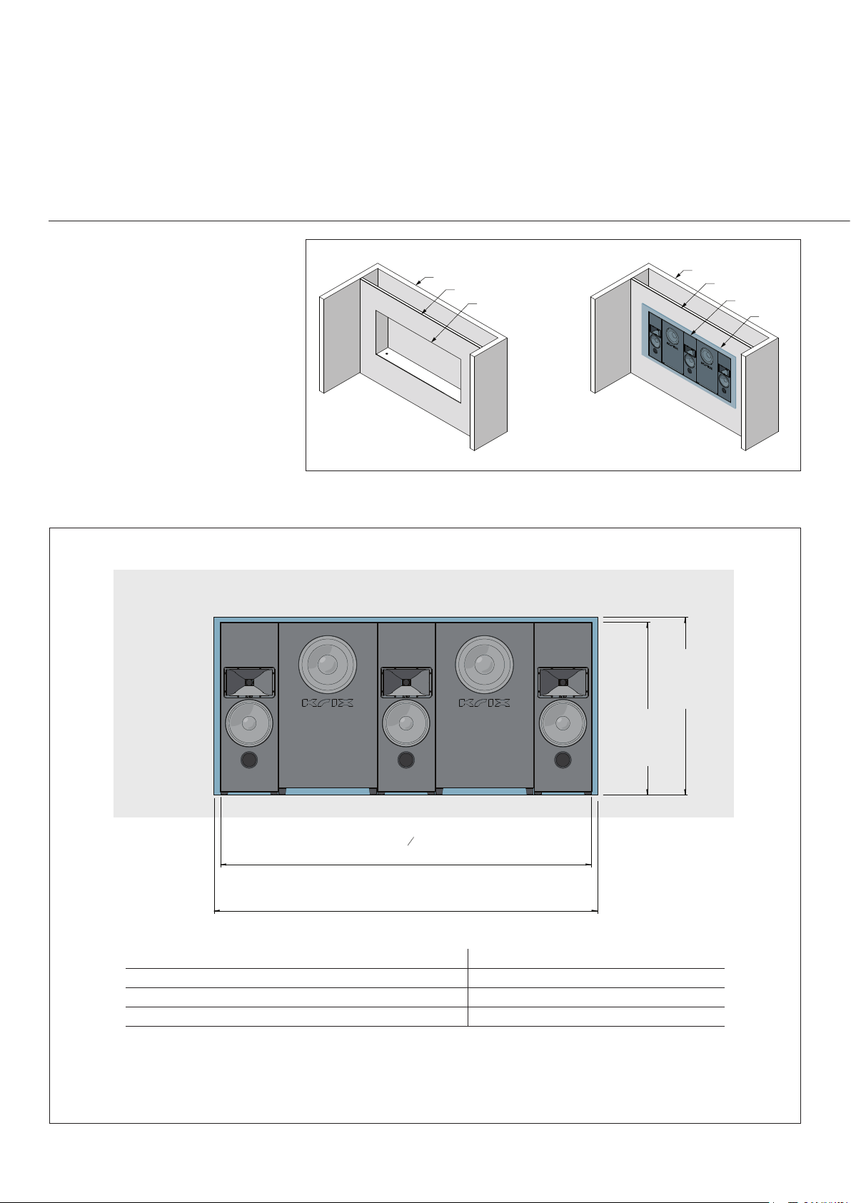
1. Fix the cavity frame to the rear wall.
(Figure 5)
2. Erect a frame for the screen wall and x
this to the floor, ceiling and adjoining
walls. (Figure 6)
3. Fix noggins in between frames so that
plasterboard or engineered timber
board can be xed. At this point, it is
recommended to insulate the void around
the speaker cavity as much as possible
using bulk insulation or similar. The more
material placed into the cavity, the better
for sound energy absorption. (Figure 7)
4. Finish the wall off using plasterboard
or timber board on the wall panels and
timber board on the cavity floor. (Figure 8)
• It is important to use a timber board with a
minimum thickness of 16mm for the cavity
floor.
• A hole for the speaker cabling is best
placed at the front corner of the cavity
floor.
1
2
3
4
Cavity frame Screen wall frame
Fix noggins in
between frames Plasterboard
Cavity floor
MDF / Ply or similar
Hole for cables
Plasterboard
B
C
DETAIL C
Bulk insulation
MX Speaker
Bulk insulation
Corner Bead
Plasterboard
Timber board
J Bead
Speaker wire
DETAIL B
Figure 5
Figure 7
Figure 6
Figure 8
Figure 9

11
SCREEN WALL CONSTRUCTION
Isolated from rear wall
Using this construction method, the
objective is to de-couple the false wall and
speakers from the adjoining room wall. The
shelf studwork supporting the MX modules
is xed securely with construction adhesive
in conjunction with screws or nails to the
baffle wall but is not directly connected to the
adjoining rear wall.
Vertical studs at the rear of the support
shelf should be secured to the floor, ceiling
and side walls. To reduce the incidence of
sound transmission, additional sheets of
plasterboard can be applied to the inside
face of the adjoining wall.
It is also strongly recommended that the
cavity created between the false wall and
adjoining room wall should be lled with bulk
ll insulation of a sufcient density to contact
the facia sheeting. This will avoid the storage
of vibrational energy both within the structure
and standing wave build-up within the void.
1. Erect a false wall frame adjacent to the
rear wall. Fix this wall to the floor and the
ceiling. (Figure 10)
• Where possible, ll cavity with bulk
insulation and then line the frame with
plasterboard or other sheeting.
2. Erect a frame for the screen wall, and x
this to the floor, ceiling and adjoining
walls. (Figure 11)
3. Fix noggins in between frames so that
plasterboard or engineered timber board
can be xed. (Figure 12)
• At this point it is recommended to insulate
the void around the speaker cavity as
much as possible using bulk insulation
or similar. The more material placed into
the cavity, the better for sound energy
absorption.
4. Finish the wall off using plasterboard
or timber board on the wall panels and
timber board on the cavity floor. (Figure 13)
• It is important to use a timber board with a
minimum thickness of 16mm for the cavity
floor.
• A hole for the speaker cabling is best
placed at the front corner of the cavity
floor.
4
False wall
Screen wall
Fix noggins
in between frames Plasterboard
Cavity floor
MDF / Ply or similar
Hole for cables
Plasterboard
1
2
3
F
G
F
DETAIL F
DETAIL G
Corner Bead
Plasterboard
Timber board
J Bead
Speaker wire
MX Speaker
Bulk insulation
False wall
Bulk insulation
Figure 10 Figure 11
Figure 12 Figure 13
Figure 14

12
SUBWOOFER SETUP AND CONFIGURATION
The MX-10 system features a dual subwoofer conguration. It is possible to wire up a pair of subwoofer loudspeakers in the following ways:
Note - By wiring the subwoofers in parallel, the load impedance presented to the amplier is halved to 2 Ohms, which consequently demands
double the output current from the amplier. Care should be taken to ensure that the specications of the amplier explicitly allow the increased
loading of 2 Ohms, especially when used in a bridged mono conguration. Check the amplier manual for wiring details if a bridged mono
conguration is desired.
It is strongly recommended to run separate cabling for all channels in the Series MX system back to the central amplier rack to permit future
flexibility with the wiring conguration.
Outputs
1
INDIVIDUAL CHANNEL
Stereo Power amplifier
2
4 Ohm load on the amplifier
Output
1
SERIES
Mono Power amplifier
8 Ohm load on the amplifier
Output
1
PARALLEL
Mono Power amplifier
2 Ohm load on the amplifier
Each channel of a stereo power amplier is
connected to each subwoofer separately.
Utilising a single channel amplier in the
series conguration, both subwoofers
are wired in series across a single pair of
output terminals.
Utilising a single amplier channel, both
subwoofers are wired in parallel across a
single pair of output terminals.
Figure 15

13
WIRING
The terminals for each speaker are located at
the rear of the speaker. Wiring the speakers
will need to be done before placing the
speakers into the cavity.
The left, centre and right main speakers are
not designed to be connected to an amplier
in a bi-amp conguration. Each main speaker
has only one set of speaker terminals, so
therefore only one length of 2 core speaker
cable is required.
Processors, ampliers and other components
may be mounted remotely in equipment
racks at considerable distances from the
screen loudspeakers. Therefore, the use of
high quality, flexible, multi-stranded copper
cables of suitable gauge are recommended
for best performance.
For cable runs up to 10m in length, a
minimum 14AWG gauge cable should be
specied for the main left, main centre and
main right loudspeakers, and at least 12AWG
cable for the subwoofers. For longer cable
runs consider using thicker cable. If in doubt,
consult your Krix authorised dealer or system
designer for recommendations regarding the
gauge of cable.
Wire Size 4 Ω Load 6 Ω Load 8 Ω Load
18 AWG (0.823 mm2) 4.9 m (16 ft) 7.3 m (24 ft) 9.7 m (32 ft)
16 AWG (1.31 mm2) 7.3 m (24 ft) 11 m (36 ft) 15 m (48 ft)
14 AWG (2.08 mm2) 12 m (40 ft) 18 m (60 ft) 24 m (80 ft)
12 AWG (3.31 mm2) 18 m (60 ft) 27 m (90 ft) 36 m (120 ft)
10 AWG (5.26 mm2) 30 m (100 ft) 46 m (150 ft) 61 m (200 ft)
t

14
EQUALISATION
Due to the use of Krix constant directivity
horns and waveguides, the MX systems have
an advantage over conventional speakers as
they deliver more direct sound to the listener
and less sound reflecting off the walls and
ceiling. The baffle wall design of the MX
system also launches the sound from a flat
plane, ensuring the frequency response is
unhampered by acoustic diffraction effects
and front wall reflections associated with
conventional home theatre installations. The
MX systems are therefore less influenced by
the acoustics of the room.
Before attempting to perform equalisation
of your processor or receiver, please ensure
that adequate attention has been given to the
acoustics of the room and acoustic treatment
options have been explored. Equalisation can
only partially compensate for a room with
poor acoustics.
As an initial step, Krix suggest conguring
your AV receiver/processor with manual
equalisation settings to achieve a simple and
faithful re-production of the source material.
Automated equalisation procedures may
also be employed, but the results will
vary depending on the algorithms and
microphone placement techniques.
Speaker distances and dB levels
Automated speaker conguration systems
are very good at setting the speaker distances
(delays) and setting dB levels for each
speaker in a system. If using this approach, it
is advised to check the settings manually for
any anomalies. In some instances, increasing
the centre channel level by 1-3dB is preferred
for increased dialogue intelligibility. Adjusting
the subwoofer level manually is often required
to suit the listener preferences. Boosting or
cutting the subwoofer level by up to 9dB is
not uncommon to achieve the desired result.
Dynamic Compression / Night Listening
The MX systems are capable of reproducing
the full dynamic range of a movie, therefore it
is recommended that dynamic compression
or night listening mode settings are disabled
in both the AV receiver/processor and blu-ray
player conguration menus. This will allow
the reproduction of the movie soundtrack’s
full dynamic range, as the director intended.
Dynamic Equalisation / Loudness Controls
‘Loudness’ type settings adjust the
equalisation of the system by boosting the
bass and treble due to the human ears lack
of acuity over these frequency ranges at low
listening levels. Unless you intend to do a
lot of listening at low volume levels it is best
to disable this setting to maintain a faithful
reproduction of the source material.
Room equalisation
The native response of the MX system
is designed to be consistent across the
frequency range, however some room
equalisation is often benecial in tuning the
response of the system to the environment.
Room equalisation involves dealing with
the somewhat complicated subject of room
acoustics and to clarify this often-confusing
subject it may help to consider the different
characteristics of the room environment and
system equalisation separately.
Room size and ‘liveness’ /
reverberation time
The reverberation time of the room is the
time taken for reflected sound energy in the
room to reduce to a low level. Highly treated
rooms have lots of absorbing surfaces
that are particularly effective at higher
frequencies. This type of room can benet
from a lift in the treble to avoid the system
sounding too dull or ‘soft’. Alternatively, larger
rooms may be perceived as sounding too
bright when combined with speakers that
have a flat frequency response and so a
gentle treble roll-off may be preferable. The
MX systems have a slight treble roll-off and
therefore will tend to sound most balanced
in larger, moderately treated rooms. In smaller
and/or well treated rooms, some treble lift
is recommended. Also, some treble lift may
be required to compensate for treble loss
through perforated acoustic screens. Woven
screens are acoustically superior and suffer
from very little treble loss.
Speaker size
Automated setup procedures may also be
used to set the size of each speaker, but
the results should be checked and adjusted
where necessary.
Although the main speakers are physically
‘large’, setting them to small allows the lower
bass frequencies to be sent to the subwoofers
that are better suited to reproducing the
lowest frequency content.
MX-10 Main – recommended to set speakers
to small with 60Hz crossover
Subwoofer power amplifier
configuration
Limiter:
The use of a power amplifier’s soft limiter
function is strongly recommended on MX
subwoofers.
If the power amplifier driving the subwoofers
is inadvertently overdriven on program
peaks, the use of an effective soft limiter
will protect the loudspeaker driver against
clipping damage and will also reduce the
incidence of adverse distortion when the
amplifier is faced with signals in excess of its
peak rating.
High pass lter
The MX subwoofer can benet from the
use of an appropriately selected high
pass lter. By ltering out the subsonic
frequencies, the overall system power
handling is improved.
MX10 – 25Hz high pass,
24dB /Oct,
Butterworth
!

15
EQUALISATION
Standing-wave issues
Small to moderate size rooms with standard
height ceilings are prone to standing wave
issues below 500Hz, resulting in peaks and
dips in the system response. Automated DSP
based solutions can be good at addressing
these issues but results will vary depending
on the algorithms employed by the DSP and
the number and positions of the microphone
measurement points used during the
equalisation process. Small to moderate size
rooms tend to skew the bass and mid-bass
response of the system due to the close
proximity of the sidewalls and ceiling to the
speaker array. Applying some cut to the mid-
bass (100-250Hz) region in small to medium
rooms can help to combat the issues
mentioned above.
Automated room correction
and speaker equalisation.
There are many room equalisation products
on the market that attempt to combat the
issues highlighted previously, but these
systems often target a flat frequency response
which can sound too bright, forward and harsh
in an average home cinema environment.
Some also pull too much energy out of the
mid bass region, resulting in a ‘thin’ sounding
system that lacks ‘warmth’ and ‘weight’. Listen
for these issues when evaluating the results
of an automated room correction system.
Manual graphic equalisation.
Manual graphic equalisation allows for a
gentler equalisation curve to be applied
allowing the large ‘cinema sound’ of the MX
system to be maintained. Below are some
suggested equalisation settings to use for
the MX systems.
Use these settings as a guide when equalising
an MX system:
Highly treated room under 8m deep
Frequency Gain
63Hz -3dB
125Hz -3dB
250Hz -3dB
500Hz -2dB
1kHz -1dB
2kHz 0dB
4kHz 0dB
8kHz 0dB
16kHz +4dB
Highly treated room over 8m deep
Frequency Gain
63Hz 0dB
125Hz 0dB
250Hz 0dB
500Hz 0dB
1kHz 0dB
2kHz 0dB
4kHz 0dB
8kHz 0dB
16kHz +3dB
Lightly treated room under 8m deep
Frequency Gain
63Hz -3dB
125Hz -3dB
250Hz -3dB
500Hz -2dB
1kHz -1dB
2kHz 0dB
4kHz 0dB
8kHz 0dB
16kHz +1dB
Lightly treated room over 8m deep
Frequency Gain
63Hz 0dB
125Hz 0dB
250Hz 0dB
500Hz 0dB
1kHz 0dB
2kHz 0dB
4kHz 0dB
8kHz 0dB
16kHz 0dB

krix.com
Krix Loudspeakers Pty Ltd
14 Chapman Road
Hackham SA 5163
Australia
T 61 8 8384 3433
F 61 8 8384 3419
Table of contents
Other Krix Home Theater System manuals