Kronoterm WPG 7 User manual

Owner’s Manual
for heat pumps water-water, brine-water and
air-water
The instructions for use have to be handed over to the end user.
ENG
Id.: 17-16-19-2972-04 | 6.2018

Owner’s manual for heat pumps water-water, brine-water and air-water
Id.: 17-16-19-2972-04 | 6.2018
Printed in Slovenia, copyright: Kronoterm d.o.o.
This document is copyrighted. Any use outside the provisions of the copyright law without the
permission of Kronoterm d.o.o. is illegal and punishable by law. All previous versions of this
document are void. We reserve the right to make changes and mistakes in print.

6.2018
3
Content
Content .............................................................................................................................................3
1
Instructions for the use of the documentation ..........................................................................5
1.1
To the buyer...................................................................................................................... 5
1.2
Important information........................................................................................................5
1.3
Symbols ............................................................................................................................5
1.4
Attached documentation...................................................................................................5
1.5
Glossary of used terms and conceptions ......................................................................... 6
2
General facts about the heat pump ..........................................................................................7
2.1
What is a heat pump.........................................................................................................7
3
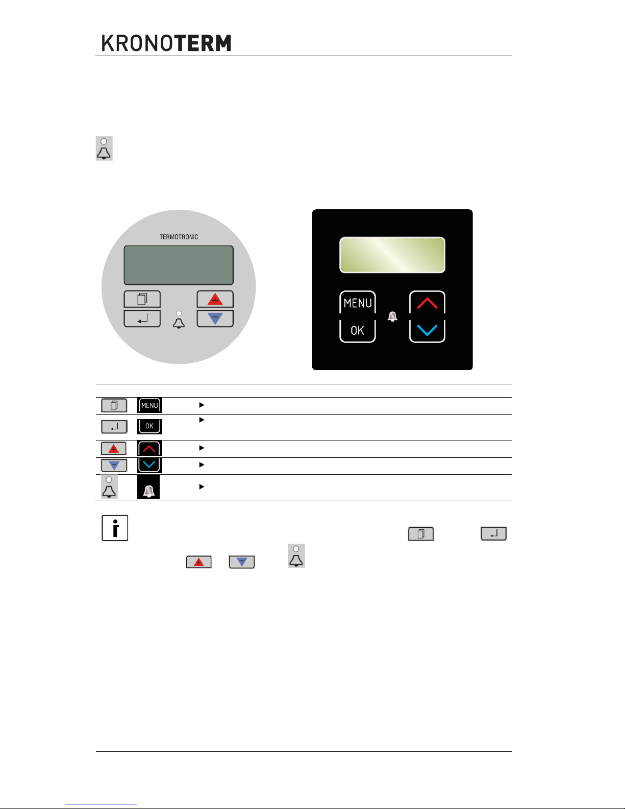
TERMOTRONIC controllers .....................................................................................................8
3.1
General .............................................................................................................................8
3.2
Controlling the device and heating system.....................................................................10
3.3
Activating the electrical power supply of the device .......................................................11
3.4
Activating the device.......................................................................................................11
3.5
Operation of the device ..................................................................................................11
3.6
Standby...........................................................................................................................12
3.7
Operation HP STOP .......................................................................................................12
3.8
Device HP STOP ............................................................................................................12
3.9
Power outage..................................................................................................................12
3.10
Display of the state of the device....................................................................................13
3.11
Setting parameters .........................................................................................................13
3.12
Setting the language.......................................................................................................14
4
Quick settings .........................................................................................................................15
4.1.1
Setting room temperature with the spatial corrector KT-2......................................15
4.1.2
Setting room temperature with the spatial corrector KT-1......................................16
4.1.3
Setting the room temperature with a room thermostat ...........................................17
4.2
Setting the temperature of heating water .......................................................................17
4.3
Setting the temperature of DHW ....................................................................................19
4.4
Changing the operational mode - winter/summer mode ................................................20
4.4.1
Changing the operating mode ................................................................................20
4.5
Setting the cooling temperature......................................................................................21
4.6
Switching on the additional heat source .........................................................................22
4.7
Manual activation of the additional heat source .............................................................23
5
Advanced settings ..................................................................................................................25
5.1
Heating settings ..............................................................................................................26
5.1.1
Heating water control mode....................................................................................26
5.1.2
Weather controlled heating – heating curve ...........................................................27
5.1.3
Heating based on constant temperature ................................................................30
5.2
Operating mode ..............................................................................................................32
5.3
Setting the cooling system..............................................................................................32
5.3.1
Active cooling (only in reversible models) ..............................................................32
5.3.2
Passive cooling.......................................................................................................33
5.4
Schedules .......................................................................................................................34
5.4.1
Operating mode ......................................................................................................34
5.4.2
Setting operation schedules ...................................................................................34
5.5
Alternative source: ..........................................................................................................36
5.6
Set the temperature for the heating water for heating the pool......................................38
5.7
Programme for drying screeds .......................................................................................39
5.7.1
Standard programme..............................................................................................39
5.8
Meters for operating hours .............................................................................................40
5.9
Setting the date, hour and day of the week....................................................................41
5.10
Remote turn on/off ..........................................................................................................41
5.11
PV signal.........................................................................................................................41
5.12
Silent operation mode.....................................................................................................42
6
User menus and parameters ..................................................................................................43
6.1
Menu structure................................................................................................................43
7
Registration of the heat pump into the cloud (WEB) ..............................................................49
8
Information display of operation .............................................................................................50

4
6.2018
8.1
Diagnostic displays ........................................................................................................ 53
9
Disruptions in operation, alarms and troubleshooting............................................................ 54
9.1
Errors and alarms in normal operation mode................................................................. 54
9.2
Troubleshooting ............................................................................................................. 56
9.2.1
Air-water device type.............................................................................................. 56
10
Device maintenance............................................................................................................... 60
11
Settings of your heating system at start-up............................................................................ 61

6.2018
5
1 Instructions for the use of the documentation
Before first use, read the instructions for use thoroughly and learn its content. You will learn the
purpose, functions and the handling procedures for the device.
In case of malfunctions of the heating system first consult section 9 and consult your installer who
will find the reason for the malfunction and resolve it. In case the malfunction cannot be resolved,
he will contact the customer service of the manufacturer who will resolve the malfunction.
1.1 To the buyer
We thank you for the trust you have shown by buying our heat pump. With the purchase of the heat
pump KRONOTERM you have become the owner of a modern, high-quality and highly efficient
device for heating and cooling which saves energy, uses renewable sources and thus maintains
the environment clean. Future generations will be grateful for your decision.
1.2 Important information
The instructions are written to give you information on all the needed activities before the first and
further use. The manual describes the process of setting up and use of the device.
NOTE
In case the product shall be given to a third person for use, the manual has to be handed
over to them as well.
Incorrectly set parameters of the control unit can lead to stoppage or incorrect operation of the
device. To reduce risk the manual points out important information with the use of symbols. Follow
all general safety instructions and warnings connected with the operation.
1.3 Symbols
This symbol marks important information for the user.
A NOTE is a notification which holds important information regarding requirements of
the manufacturer and the device.
1.4 Attached documentation
Attached to the device you can find the following documentation which you are required to read
before the first use of the device:
Owner’s manual intended to familiarise the user how to operate the device.
The Installation manual intended to familiarise the installer end user with the guidelines,
requirements and warnings for correct installation and maintenance of the device.
Instructions for installing the control unit intended to familiarise the electrician and user
with the correct electrical connection, requirements and warnings as well as maintenance
of the device.
Warranty is intended for the user to prove eligibility for free repair of the device in the
warranty period in case of malfunction.

6
6.2018
1.5 Glossary of used terms and conceptions
In case of unfamiliar terms in the document, you can find the explanation here.
ALTERNATIVE SOURCE: The heat source is used for systems with solar collectors,
fireplaces and wood stoves when we either do not have a heat source on hand at any
moment or an automatic switch through the signal from the controller of the device (i.e. in
a wood stove) is not possible.
ADDITIONAL SOURCE: The external heat source found alongside the device (i.e.
oil/gas/pellet/external heater furnace) or internal heat source (electrical flow heater) which
is factory integrated in certain types of devices. The spare or additional source can be used
as “assistance” to the device under the so-called bivalent point when the capacity of the
device does not suffice for maintaining the desired temperature. It can be used alongside
the device alternatively (the either-or system) – the switch is automatic.
BACKUP SOURCE: A function, which turns on the selected additional source in the event
of an error or a remote shutdown. The device operates in antifreeze mode. The device will
turn off following the confirmation of an error or interrupt signal from the remote off.
The flow heater which is installed in the device and turns on in the case of device
malfunction (in the so-called antifreeze programme). This ensures temporary operation for
bridging the time until an authorised person from the service company arrives and corrects
the error.
HEATING WATER: The liquid which flows inside the heating system (pipelines, floor, wall
and radiator heating).
DHW: The water intended for sanitary use (cleaning, showering, washing ...).
HEAT PUMP (HP): The device which takes energy from the environment, uses electric
energy to drive the device and releases heat from space heating and DHW. In the text
below the term ‘device’ will be used for the heat pump.
HW: The device takes heat from the earth.
AW: The device takes heat from the air.
WW: The device takes heat from groundwater.
Parameter NORMAL: The desired temperature of heating in the Normal mode of
operation.
Parameter ECO: Lowering the desired temperature in the Eco mode of operation.
Parameter COMFORT: Raising the desired temperature in the Comfort mode of operation.
Operator: Is a natural or legal person who has real control over the technical operation of
the products and equipment covered in the directive (EU) No. 517/2014; a member state
can impose operator obligations on the owner in clearly defined and specific cases.

6.2018
7
2 General facts about the heat pump
2.1 What is a heat pump
A heat pump is a device which uses renewable energy sources (air, earth and water) and enables
us economical and ecologically friendly heating and cooling of the building as well as heating DHW.
Whether it is intended for internal or external installation depends on the device itself. Heat pump
operation:
HEAT SOURCE
HEAT PUMP
HEATING SYSTEM
The device takes heat from the environment or source (groundwater, earth, air) and transfers it to
the water in the heating system. This is achieved with the process of evaporating the coolant in the
evaporator which is a heat exchanger especially designed for this task. This coolant is compressed
in the compressor in the next circuit to a higher pressure which makes the temperature of the
coolant rise to a temperature higher than the temperature of the heated water. This coolant then
condenses in the water-cooled condenser where the heat taken from ground water/earth/air and
electrical energy needed for the operation of the compressor are transmitted to the heating water.
The heating water can be heated up to 65 degrees Celsius and more through this process
(depending on the operating conditions of the device); this makes the devices suitable for
renovating older heating systems.
Evaporator Condenser
Expansion
Compressor
Energy of
the
surrounding
s
Drive power
Heat of the air
Heat of the earth
Heat of the
water

8
6.2018
3 TERMOTRONIC controllers
3.1 General
TERMOTRONIC is a self-adapting controller for controlling the heat pump (hereinafter the DEVICE)
and the heating system. It controls the operation of the device so as to ensure the most efficient
way to produce the desired temperature of the building based on the needs of the heating system
and outside temperature.
The TERMOTRONIC controller offers controlling of the device and the heating system of the
building (no more than 4 heating circuits) as well as controlling the heating with an alternative heat
source, passive cooling (in the case of using the earth-water or water-water device), active cooling
with the device, heating of pools, heating DHW with the device and/or alternative heat source and/or
backup source.
Possibility of controlling the elements of the heating system with the controller TERMOTRONIC:
EXPANSION I/O MODULE
BASIC I/O MODULE

6.2018
9
MARK DESCRIPTION
CLOUD/WEB Remote control of heating system via computers and smart mobile devices.
KT-1(2) Room collectors KT-1(2) – control unit of the heating circuit.
A, B, C, D Heating circuit (heating/cooling).
1 DHW heating.
2 Room heating.
3 Room cooling.
4 Weather controlled room heating.
5 Passive room cooling.
6 Heat pump control.
7 Control of additional source (DHW, electrical heater ...).
8 Control of auxiliary electrical heater for DHW.
9 Control of alternative heating source (SER - solar energy receivers or solid
fuel DHW).
10 Control of alternative heating source for DHW (SER or solid fuel DHW).
11 SER cooling.
12 Warm DHW circulation
13 Swimming pool heating.
MD1 Basic input-output module MD1.
MD2 Expansion input-output module MD2.
Modbus Communication with the control system of the building (BMS) or smart
installation.
For performing the connection to the TERMOTRONIC controller see chapter “Connection of the
internal unit” in the installation manual.
In addition to the listed control options the TERMOTRONIC controller also has a number of safety
mechanisms built in which protect the device and the heating system from malfunction and defects.

10
6.2018
3.2 Controlling the device and heating system
The device and heating system can be controlled with the use of 4 buttons on the controller interface
TERMOTRONIC. The controller interface has a 4-line LCD screen which displays the current state
of the device or controller and a LCD light indicator of malfunctions in the operation of the device
(ALARM).
The controller interface TERMOTRONIC in devices:
WPL in WPG 7 – 21 kW WPLV, WPL + HM, in WPG 30 – 110 kW
BUTTON BUTTON FUNCTION
MENU: Scrolling through the main menu and sub-menus.
ENTER:On, off, accessing the menu, accessing the settings and
confirming selected values.
»+«: Selecting the values, scrolling up the menus and sub-menus.
»-«: Selecting the values, scrolling down the menus and sub-menus.
ALARM: Indicator of device malfunction.
NOTE
Below only the following symbols are used in grey colour: (MENU),
(ENTER), (+), (-) and (ALARM).

6.2018
11
3.3 Activating the electrical power supply of the device
The device’s electrical supply is turned on by switching:
The main switch into position “1” and
Circuit breakers of the electric power supply of the device (1-ON).
The main switch of the device earth-water,
Water-water (WPG).
Circuit breakers for the power supply of the air-
water device (WPL, WPLV).
By switching on the main switch or circuit breaker of the electrical supply the device is live but
still not working. After the startup delay time the device turns on.
3.4 Activating the device
After switching on the main switch or circuit breaker the interface screen displays the current state
of the device - standby for the short delay time. The device is not operational yet.
NOTE
The temperature values can differ from the ones displayed on the picture. This also
applies for all following pictures.
NOTE
If before shut down the device was in a state of HP STOP (HP STOP), it returns to the
HP STOP mode after switching on the circuit breakers. The display displays HP STOP.
The device is turned on by holding the (ENTER) key for 3 seconds - see below
for more information.
3.5 Operation of the device
After the start-up delay time the device starts operating in the selected mode (heating, cooling or
heating DHW) according to present needs. The display displays the status:
In the case the set temperature parameters (Heating, Return, DHW ...) is reached, the device
displays Standby.
Standby…………………………….
Heating 35.5°C
Return 35.3°C
DHW 49.0°C
Heating………………………………
Heating► 35.5°C
Return 32.3°C
DHW 49.0°C

12
6.2018
NOTE
Depending on the type of device the delay lasts from 30 to 300 seconds.
3.6 Standby
The device enters standby state when the values of the selected parameters Heating, Cooling,
DHW , device protection ... are reached. The display of the interface displays the status:
NOTE
The device enters the standby mode also when any operation protection is active
(compressor start-up delay, insufficient water flow); see chapter 9.
3.7 Operation HP STOP
In case you want to shut down the device, press the (ENTER) key and hold it for 3 seconds.
The operation of the device is interrupted but the device is still live.
The device can be turned on again by pressing the (ENTER) key and holding it for 3 seconds.
3.8 Device HP STOP
The device can be disconnected from the power supply by switching the main switch to position “0”
or disconnecting the circuit breaker (the electrical power supply fuses).
NOTE
WPL devices must not be disconnected from the power supply for a longer time (via the
main switch or circuit breakers) because by doing so you disable the devices protection
against water freezing in the system which leads to complete device malfunction. Here
the requirements from the installation manual have to be considered.
3.9 Power outage
In case of a power outage the device ceases to operate. After power is restored the device
undergoes 300 seconds of protection mode and then automatically returns to the mode before the
power outage. In the case of a power outage the controller retains all settings set before the
outage.
NOTE
In case of a power outage longer than 2 hours air-water models with a water connection,
water has to be drained from the connecting pipes between the external and internal
device. Operate in accordance with the requirements in the installation manual.
Standby…………………………….
Heating 35.5°C
Return 35.3°C
DHW 49.0°C
HP STOP…………………………….
Heating 35.5°C
Return 32.3°C
DHW 49.0°C

6.2018
13
3.10Display of the state of the device
After activating the power supply the device displays the current state of the device on the display
according to the operating mode and values of basic parameters of the heating/cooling system of
the building; see chapter 8.2.
Keys and allow moving up and
down the basic display.
READING ON THE DISPLAY DESCRIPTION
Standby Current state of operation.
Heating ►235.5 °C Set or calculated temperature of heating (only in
winter mode).
Return 32.3 °C Current temperature of the return.
DHW 49.0 °C Current temperature of DHW.
TD outside 88
7 °C Current outside temperature.
TD60 in 12 days Time left until the start of DHW thermal desinfection
(i.e. next thermal desinfection will begin in 12 days).
Setting of DHW thermal desinfection is controlled by
changing parameters TD and HT every described in
section 6 located in the main menu DHW.
2016/02/10 12:24 TUESDAY Current time and day of the week. Setting the time
and day of the week is described in section 5.9.
NOTE
No. 2 means the number of days until automatic mode switch.
No. 88 represents the activation delay time of the additional source in minutes.
The symbol displays the activation of the electric heater.
3.11Setting parameters
All parameter settings of the device’s operation and heating/cooling system of the building are set
as described below.
1.
For entering the user menu press the key
(MENU) on the basic display.
2.
The currently chosen menu is marked by the
symbols > < (CHOOSE).
Keys or select the desired menu.
To enter the selected menu, press the
(ENTER) key.
For exiting the menus to the basic display press
the (MENU) key.
The display shows only those menus which were
actually activated during the start-up of the
device!
Standby……………………………..
Heating
►2
35.5°C
Return 32.3°C
DHW 49.0°C
Standby………………………………
Heating 35.5°C
Return 32.3°C
DHW 49.0°C
Heating <
1. Circuit
2. Circuit
3. Circuit

14
6.2018
3.
After entering the selected menu the initial
parameter is marked with the symbols
> < (CHOOSE).
The key selects the parameter you want to
change. When you select the parameter, press
key (ENTER).
4.
The signs * * along the chosen parameter
indicate the “mode setting” (SET). The value of
the chosen parameter can be changed to the
desired value by using keys or . To
confirm the settings press key (ENTER).
5.
After confirming the settings by pressing key
(ENTER), the signs * * (SET) change
back into signs > < (CHOOSE).
For changing the value of other parameters,
repeat the process.
After completing the settings you can return to
the main menu by pressing the key
(MENU).
NOTE
MARK
DESCRIPTION
> <
The arrows on the sides indicate the presently selected
parameter/menu (CHOOSE).
* *
The stars on the sides indicate the mode of setting the chosen
parameter (SET).
►A full arrow with the name of the parameter (i.e.: DHW ►50°C)
indicates the current operation of the circulation pump or the position of
the switching valve (i.e. DHW). In the case of more circulation pumps of
the heating system being in operation, more full arrows are displayed.
3.12Setting the language
The TERMOTRONIC controller enables setting different display languages. To set a language of
your choice, follow the steps below or set the language thought the Home Cloud application.
Press key (MENU) in the basic menu.
Use the key to choose the Mode (Mode,
Regime, Betriebsart, Nacin). menu.
To confirm the settings press key (ENTER).
C/W I
Schedule
Normal 35.5°C <
Eco -2.0°C
C/W I
Schedule
*Normal 35.5°C *
Eco -2.0°C
C/W I
Schedule
Normal 39.1°C <
Eco -2.0°C
Standby…………………
Heating 35.5°C
Return 32.3°C
DHW 49.0°C
Mode <
Temperatures

6.2018
15
Use the button to choose the parameter
Langugage EN (Jezik SI, Lingua IT, Sprache DE,
Jezik CRO).
Press to go it to SET mode and use the
button to select the desired language.
To confirm the settings press key (ENTER).
4 Quick settings
NOTE
The parameters of the TERMOTRONIC controller were set according to project
documentation of the heating/cooling system, recommendations of the manufacturer of
the device and your requests by the authorised contractor for commissions at
commission. At handover, the contractor for commissions is obliged to thoroughly
present you with the possible ways of the device’s operation and explain the setting
modes of the parameters important for the user.
The basic function of the device is space heating and heating the DHW. The controller of the device
calculates the optimal needed temperature of the heating water to achieve the desired air
temperature of the room in dependence on the outside temperature.
Setting the temperature of heating/cooling
The temperature in the heated/cooled room is controlled in two stages, by setting the temperature:
1. of the room with the spatial corrector or thermostat and
2. the heating/cooling water in the accumulator and heating/cooling circuits on the controller
TERMOTRONIC.
NOTE
In case despite the change in the setting of the temperature with the spatial corrector or
thermostat after a longer period of operation of the heating/cooling circuit (in floor
heating this could last up to 4 days) the desired room temperature was not achieved,
check the heating water temperature settings. For settings see chapter 4.2.
4.1.1 Setting room temperature with the spatial corrector KT-2
The spatial corrector KT-2 enables an advanced and very easy settings of room temperature and
basic functions of the device.
By pressing the key or the
display displays the currently set
room temperature. The temperature
is marked by an orange border.
By pressing the key or again
you adjust the desired room
temperature. You confirm the
change by pressing the OK button,
although, the change auto-saves in
8 seconds.
C/W ALL I
D8-PV Cooling
Silent mode
Language EN <

16
6.2018
NOTE
The space corrector influences the whole heating circuit and not the temperature of the
individual room. The desired room temperature where the spatial corrector is located
in the reference temperature for all other rooms of the heating circuit controlled by this
spatial corrector.
Before raising the temperature of heated water or the desired room temperature on the
spatial corrector make sure the valves on the heat sources in the room where it is too
cold for you, are completely or sufficiently opened. If the temperature of other rooms is
too high or too low open or close the valves for floor heating or radiators where the
deviations from the desired temperature take place.
NOTE
For maintaining the correct operation of the heating system you have to choose a
suitable operating mode - winter (heating and DHW) or summer (DHW and cooling -
only in certain models). For choosing the mode see chapter4.3.
NOTE
A detailed description of the settings and additional functions (weather report, DHW,
operating mode, information about the state of the device ...) see the manual for the
spatial corrector KT-2.
4.1.2 Setting room temperature with the spatial corrector KT-1
The spatial corrector KT-1 enables basic settings of room temperature.
By pressing the key or the LED display displays the
currently set desired room temperature. By pressing the
key or again you adjust the desired room
temperature. By pressing the keys you adjust the values
by 0.5 °C. The change is confirmed automatically.
Quick setting: By pressing and holding the key the
temperature setting changes in steps of 1 °C.
NOTE
The space corrector influences the whole heating circuit and not the temperature of the
individual room. The desired room temperature where the spatial corrector is located
in the reference temperature for all other rooms of the heating circuit controlled by this
spatial corrector. Before raising the temperature of heated water or the desired room
temperature on the spatial corrector make sure the valves on the heat sources in the
room where it is too cold for you, are completely or sufficiently opened.
If the temperature of other rooms is too high or too low open or close the valves for
floor heating or radiators in the rooms where the deviations from the desired
temperature take place.
NOTE
For maintaining the correct operation of the heating system you have to choose a
suitable operating mode - winter (heating and DHW) or summer (DHW and cooling -
only in certain models). For choosing the mode see chapter4.3.
NOTE
You can find a detailed description of settings and additional functions in the manual
for the spatial corrector KT-1.

6.2018
17
4.1.3 Setting the room temperature with a room thermostat
For setting the room temperature with a room thermostat consult the manual which come with the
thermostat or consult the installer.
NOTE
In case the thermostat is turned on all this time and the heating system does not
heat/cool the space to the desired temperature, check the settings of temperatures of
the heating system on the device.
NOTE
For choosing the function of heating or cooling an appropriate thermostat has to be
installed which allows both functions.
NOTE
For maintaining the correct operation of the heating system you have to choose a
suitable operating mode - winter (heating and DHW) or summer (DHW and cooling -
only in certain models). For choosing the mode see chapter 4.4.
4.2 Setting the temperature of heating water
Upon start-up the control of the heating water temperature of your heating system was set to
Heating curve mode which ensures the most energy efficient operation of the device. In case the
automatically calculated temperature of the heating water (in accordance with the external
temperature) is insufficient for ensuring the comfort of living in the rooms, the temperature of the
heated water can quickly be raised or lowered by changing the parameter of cooler/hotter (C/W).
The values of the parameter C/W are adjusted in the menus 1. Circuit 2. Circuit 3. Circuit or
4. Circuit depending on which temperature you want to change. If you want to change (raise/lower)
the temperature of the heated water for the whole building or heating system, change the parameter
C/W in the menu Heating.
NOTE
Upon start-up the heating water temperature control was set to Heating curve mode.
The authorised contractor for commissioning noted your heating water settings of the
heating circuits into chapter 11.
By setting the parameter C/W you set the number of temperature steps (one temperature step
equals 1 °C) for which you want to raise or lower the temperature of heated water. You perform the
settings in the following steps:
1.
Press key (MENU) in the basic menu.
2.
In the user interface, use the key and
choose menu 1. Circuit and press the key
(ENTER).
Standby………………………………
Heating 35.5°C
Return 32.3°C
DHW 49.0°C
Heating
1. Circuit <
2. Circuit
3. Circuit

18
6.2018
3.
The first line has the parameter C/W
selected.
To set the parameter press key (ENTER).
6.
* * appear along the chosen parameter. The
keys and change the value of the
parameter C/W. This raises or lowers the
temperature of heated water.
7.
Each pressing of the key raises/ lowers
the temperature of the heating circle for one
temperature step (<, >).
To confirm the settings press key
(ENTER).
7.
After conformation the controller calculates the
new temperature setting for the heating circuit
or heated water according to the external
temperature (in case of weather control).
For returning to the basic view press the key
(MENU) twice.
For advanced changing the temperature of the heated water control mode of the heating system
see chapter 5.1.
NOTE
The temperature of heated water can be raised or lowered for no more than
four temperature steps.
The heating and individual circuits settings are separated from the cooling, this
is why all settings for heating remain unchanged with the change of the mode
into cooling. The same is true for parameter settings in the menu Cooling,
1. Circuit, 2. Circuit, 3. Circuit, 4. Circuit and Heating, which are separated
so as to maintain all settings when changing the heating Mode
(winter/summer).
For heating curve you can choose various temperature modes of operation
with setting daily and weekly schedules. See chapter5.4.
NOTE
In case of radiator heating for a significant change, change the parameter C/W for 2 or
3 temperature steps at once but only for 1 temperature step in case of floor heating.
Please note that the responsiveness of the heating system in the case of radiator
heating is quicker than in the case of floor heating. By changing the parameter C/W
several hours can pass (in the case of floor heating) before the heating system
responds properly and you can feel the change of the adjustment.
C/W I <
Schedule
Normal 35.5°C
Eco
-2.0°C
*C/W I *
Schedule
Normal 35.5°C
Eco
-2.0°C
*C/W I *
Schedule
Normal 35.5°C
Eco
-2.0°C
C/W I <
SCHEDULE
Normal 35.5°C
Eco
-2.0°C

6.2018
19
4.3 Setting the temperature of DHW
Once the temperature of the DHW falls below the set temperature minus the parameter Hysteresis
(example: DHW setting is 50,0 °C, Hysteresis setting is 5,0 °C DHW heating will start at 44,9
°C), the controller switches the device from space heating to heating DHW. Heating DHW has
priority over other modes of operation.
Setting the temperature of DHW is performed in the following steps:
1.
Press key (MENU) in the basic menu.
2.
In the user menu choose the menu DHW with
the key and press the key (ENTER).
3.
In the menu DHW in the first line the parameter
DHW is chosen. To set the parameter press key
(ENTER).
4.
* * appear along the chosen parameter. The
keys and change the value of the
parameter DHW. This raises or lowers the
temperature of DHW.
To confirm the settings press key
(ENTER).
5.
Next to the set parameter you can again find the
symbols > <.
For returning to the basic view press the key
(MENU) twice.
NOTE
The actual reached temperature of heated water in the DHW depends on the adequacy
of the DHW, pipelines, flow and ventilation of the system.
NOTE
For controlling the temperature settings of DHW in the tank you can set different modes
of operation (ECO, Comfort), daily and weekly schedules. See chapter 5.4.
Standby…………………
Heating.. 35.5°C
Return 32.3°C
DHW 49.0°C
DHW <
Additional source
Mode
Temperatures
DHW 50.0°C <
Hysteresis 5.0°C
Schedule
Circulation Sched.
* DHW
50.0°C *
Hysteresis 5.0°C
Schedule
Circulation Sched.
DHW
50.0°C <
Hysteresis
5.0°C
Schedule
Circulation Sched.

20
6.2018
4.4 Changing the operational mode - winter/summer mode
The mode of operation - winter or summer, is chosen according to season. In the time when you
do not need heating or want to cool the rooms, switch to summer operating mode. In case heating
is needed, switch to winter mode. The choice can be automatic or manual.
NOTE
If you do not switch into the summer mode operation in the summer, this can result in
higher energy consumption. The operational costs will be increased for two reasons:
The main circulation pump will switch on from time to time to check whether
the need for heating has arisen.
The additional source could also be turned on (for the protection of the heating
system) if the temperature falls below a certain point, i.e. 12 °C – this depends
on the start-up settings.
NOTE
The cooling function is only provided by reversible and WPG + passive models of the
devices.
The function of the
device according to
the chosen mode of
operation: Mode
OPERATION
Heating DHW Cooling
Winter YES YES NO
Summer NO YES YES
NOTE
In the winter mode (heating and DHW) the heating system works only for heating the
heating water of activated circles and DHW. By using the built-in external switch we
can launch manual switch on/off of the cooling mode of the device.
4.4.1 Changing the operating mode
Changing the operation from winter to summer mode is performed in the following steps:
1.
Press key (MENU) in the basic menu.
2.
In the user interface, use the key and
choose menu Mode.
3.
To choose the menu Mode press key
(ENTER).
Standby…………………………….
Heating 35.5°C
Return 32.3°C
DHW 49.0°C
Heating <
1. Circuit
2. Circuit
3. Circuit
Mode
<
Temperatures
This manual suits for next models
1
Table of contents
Other Kronoterm Heat Pump manuals

Kronoterm
Kronoterm WPLV-09-S1 NT User manual

Kronoterm
Kronoterm HM-130 S1 Parts list manual

Kronoterm
Kronoterm WPL-45-K1 HT Reference manual

Kronoterm
Kronoterm WPL-90-K1 HTT_HK Operating instructions

Kronoterm
Kronoterm WPG-07-1 HT Reference manual

Kronoterm
Kronoterm WP4 LF-502 User manual

Kronoterm
Kronoterm WP4 LF-502 Operation manual

Kronoterm
Kronoterm WP2 LF-202B User manual

Kronoterm
Kronoterm WP2 LF-202S User manual

Kronoterm
Kronoterm WP2 LF-202S Operation manual