KRUPPS SO3100K User manual

Use and maintenance manual EN
Reverse osmosis device
SO3100K


Content
1 - INTRODUCTION .............................................................................. 5
2 - TECHNICAL CHARACTERISTICS ................................................... 6
3 - SAFETY............................................................................................ 7
4 - STORAGE ........................................................................................ 7
5 - USE CONDITIONS AND PERIOD OF USE ...................................... 9
6 - INSTALLATION................................................................................. 11
7 - SPARE PARTS AND PRE-FILTRATION ............................................ 13
8 - USE .................................................................................................. 13
9 - MAINTENANCE................................................................................ 15
10 - ELECTRONIC MANAGEMENT ...................................................... 18
11 - FAULTS MANAGEMENT ................................................................ 20
12 - GENERAL DESIGN ........................................................................ 21
13 - WARRANTY STANDARDS ............................................................. 23
INSTALLATION CERTIFICATE ............................................................... 25
MAINTENANCE SHEET......................................................................... 26

- 4 -
IMPORTANT
Please read this manual carefully and follow the instructions herein for the
guarantee that your reverse osmosis system works properly.
Non-compliance with these instructions will cause the warranty to be made
void.
The manufacturer cannot be held in any way liable for any damage to people
or property caused by a failure to comply with this attached manual, which
is an integral part of the scope of supply.
This manual is valid for the SO3100K versions.
The kit is intended for use in a household environment. In particular, its use
consists of processing and supplying already drinkable water for human
consumption. Any other use is not permitted.

- 5 -
English
1 - INTRODUCTION
Osmosis is a natural phenomenon for which a solution poor in mineral salts passes
through a semi-permeable membrane then it is diluted in another one that has a greater
saline concentration.
By applying counter pressure, this procedure is inverted and you obtain REVERSE OS-
MOSIS: in fact, by pushing a solution with a high concentration of mineral salts against
a special membrane, PROCESSED WATER is obtained. Due to its structure and prop-
erties, the membrane almost completely retains dissolved salts, heavy metals, pollutant
elements, bacteria and viruses letting the water pass in all its genuine purity.
REVERSE OSMOSIS is therefore the safest and most widespread purication system
around the world; the advantages, other than basic reliability of the system, is represent-
ed by the simplicity of assembly, the very low operating costs and the total absence of
chemical products.
The SO3100K model is capable of eliminating all impurities and harmful pollutants for
health from the water. Treated water is the ideal solution for household use and delivery
since the exclusive ltration system forms a safety barrier against different pollutants in
groundwater.
2
OSMOTIC
MEMBRANE
WASTE
WATER
POLLUTED WATER
1 - NATURAL OSMOSIS
2 - REVERSE OSMOSIS
TREATED WATER
This manual is valid for the following models:
SO3100K (LCD)

- 6 -
2 - TECHNICAL CHARACTERISTICS
ELECTRICAL POWER SUPPLY 220 VAC - 50 Hz
MAXIMUM POWER 250 W
FUSES 3.15 AT
MIN/MAX SUPPLY PRESSURE 1 / 5 bar
PUMP MAXIMUM PRESSURE 9 bar
MIN/MAX WATER TEMPERATURE 5 / 35 °C
MAX PERMITTED CHLORINE 0.2 ppm
MAX PERMITTED IRON 0.1 ppm
MAX PERMITTED MANGANESE 0.1 ppm
MAX SALINITY 1500 µS/cm
MIN/MAX AMBIENT TEMPERATURE 5 / 40 °C
MAX RELATIVE HUMIDITY 95 %
NOMINAL PERFORMANCE*
MODEL PRODUCTION
25°C
RECOVERY
RATE REJECTION** SUPPLY
FLOW RATE
WORK
CYCLE
SO3100K 150 l/h
Intelligent Man-
agement, varia-
ble from 30% to
60%
92% / 95% 300 l/h 100%
* The performances in the table are average values obtained in standard test conditions,
in particular with water prepared with NaCl at 500 ppm.The conditions can greatly vary
based on the real conditions, the temperature and wear status.
**The drain is managed by a patented valve, which always allows discarding of the opti-
mal water quantity to preserve the membranes and have a higher quality of permeate
possible.

- 7 -
English
3 - SAFETY
The electrical safety of this equipment is only ensured when it is connected to an electrical
system with a sufficient ground socket and a differential switch pursuant to law.
Checking this fundamental requirement for safety is compulsory. If in doubt, require
assistance from a qualied technician.
Use of the SO3100K, as with any other equipment connected to an electrical system,
involves compliance with certain fundamental safety rules:
- do not touch the reverse osmosis purifying system with wet or damp hands or feet;
- do not detach or connect the plug in the socket with wet hands;
- do not pull the power supply cable to detach the plug from the socket;
- do not leave the reverse osmosis purifying system exposed to atmospheric agents;
- do not allow the reverse osmosis purifying system to be used by children without su-
pervision;
- before carrying out any cleaning or maintenance operation, disconnect the reverse
osmosis purifying system from the electrical mains by detaching the plug;
- in the event of a fault or poor operation, switch off the reverse osmosis purifying system
and do not tamper with it. Contact an authorised technician for any intervention; in the
event of replacement of parts of the reverse osmosis purifying system for maintenance
or due to a fault by an unauthorised technician, ensure said parts comply with legis-
lation in force.
The manufacturer cannot be held in any way liable for possible inaccuracies in this in-
struction manual due to printing or transcription errors.
The manufacturer also reserves the right to bring all changes to the reverse osmosis
purifying system, as deemed useful or necessary, without altering its basic characteristics.
4 - STORAGE
The packaged equipment must be stored in a dry place (without condensate), protected
against bad weather.The permitted temperature is 0-50°.You should consider that, even if
carefully packaged and protected, the system must be considered and handled as fragile
material. On receipt, the packaging must be opened to check the equipment is intact. If
damaged, immediately notify the carrier.

- 8 -
SO3100K
13
48
40
4 cm
39,5 cm
3,7 cm
6 cm
28,5 cm
37,5 cm
35 cm
38,5 cm
1/4
3/4
ALIMENTAZIONE
ELETTRICA
FORI PER
CONNESSIONI
ELETTRICHE
ESTERNE

- 9 -
English
5 - USE CONDITIONS AND PERIOD OF USE
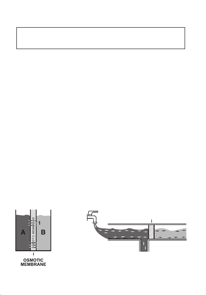
Reverse osmosis system, processing essentially consists of adjustable reduction in xed
residue in treated water.
The machine is intended for use in a closed and protected environment, not outdoors.
Its use consists of treating and supplying drinking water for human consumption and
for technical use. Any other use is not permitted.
Attention: this equipment requires regular, periodic maintenance to
guarantee the requirements of treated drinking water and to maintain the
improvements as declared by the manufacturer of the reverse osmosis
system for domestic use for the treatment of drinking water. Equipment for
the treatment of drinking water. Input water must be drinkable according to
Ministerial Decree no. 31 of 2 February 2001.
Summary table for time of use and maintenance methods
Time Assessment method Intervention to follow
Period of use 10 years Installation booklet
present
Service by
manufacturer or
disposal
Duration active carbon
lters
Most critical condition:
12 months or used up Board signalling Replacement and
sanitisation
Membrane life Most critical condition:
2 years or used up
Installation booklet
present
Replacement and
sanitisation
Machine off without
electrical supply
Over 10 days or time
uncontrolled Ascertain by calendar Filter replacement and
sanitisation
Drainage restrictor Each lter change Board signalling Restrictor replacement
For the maintenance method, see the specic chapter.
To dene the period of use and the maintenance methods, specic tests were carried
out. Furthermore, a water sample was analysed to verify the altered parameters and
compliance with MD 31 on 2 February 2001.
Important: After installation, the machine must be powered for hygiene
reasons (ushing) and to have correct management of the exhausted lter.
Sanitise and replace the pre-lter after periods of disuse longer than 10 days
in the absence of electrical power supply.
The results of drinkability testing of the water taken before and after SO3100K are outlined
below. Both tests, carried out by an accredited institute, conrm the water to be drinkable.
In particular, it is conrmed that treatment efficiently combats various parameters, in
particular conductivity, hardness and various chemical substances.

- 10 -
Chemical and bacteriological drinkability (MD 31 on 02/02/2001)
sampling date 15/11/2019 (machine appropriately adjusted)
Test U.M. Water supply SO3100K
s/n H102001
Viable micro-organisms at 36°C CFU/mil <1 <1
Viable micro-organisms at 22°C CFU/1mil <1 21
Escherichia coli cfu/100mil 0 0
Coliform bacteria cfu/100mil 0 0
Intestinal enterococci cfu/100mil 0 0
pH Unit of pH 7.44 7.25
Conductivity µS/cm 978 155
Chlorides mg/l 157 17
Sulphates mg/l 209 24
Ammoniacal nitrogen (N-
NH4) mg/l <0.1 <0.1
Nitrates mg/l 16 3
Nitrites mg/l <0.1 <0.1
Hardness °F 42 5
Oxidisability mg/l O21. 8 1. 8
Iron µg/l 9 <1

- 11 -
English
6 - INSTALLATION
Installation and maintenance should be carried out to standard by specialist
technicians, in particular in compliance with this manual, pursuant to MD 25 on 7
February 2012 and, where relevant, in compliance with the provisions outlined in
MD 37 on 22 January 2008.
The reverse osmosis purifying system was designed for installation in a closed envi-
ronment, not outdoors, in a hygienically suitable location, protected from frost. It must
also be connected to standard to the electricity mains and the drinking water mains, in
compliance with the technical characteristics outlined in chapter 2.
• For a perfect preservation, the membranes are kept in preservative substances.
Therefore, do not use the rst water produced by a new system, or on which the
osmotic membrane was replaced, but let it ow for 2 cycles of approx. 10 minutes,
with 5-minute stop intervals.
• Always install a sediment pre-lter with an adequate ow rate and characteristics
based on the system and the quality of the input water.
• Installations, repairs, interventions or changes must be carried out by authorised staff.
Before proceeding to installation, check there is sufficient space to:
• Comfortably install the hydraulic connections;
• Easily remove spare parts;
• Carry out maintenance.
Hydraulic connection:
Install the hydraulic connections following the writing on the machine, ”IN” indicates arrival of
water supply; ”OUT” indicates osmosis water to send to sampling;
”DRAIN” indicates water output to send to drainage.
Supply the machine with an adequate tubing based on the water system to be created.
Always assemble a shut-off valve (for example a lever tap), upstream of the water supply
circuit.
To check if the ow rate of the supply circuit is adequate, proceed as follows:
Install a gauge IMMEDIATELY BEFORE THE MACHINE INLET. The working system
pressure during the supply phase must be minimum 0.5 bar.
Electrical connection:
Check if the fuse is in the power supply socket of the machine. Check the characteristics
and safety requirements of the electrical system.
Position the switch on 0 (machine off) and connect the machine to the electrical system
with the specic cable.

- 12 -
Start-up:
Having connected the hydraulic system:
• Open the water slowly, checking there are no leaks.
• Press the start button
• Open the tap and allow water to ow to purge the air.
ATTENTION: Do not operate the machine without rstly opening the water. Operating a
dry pump could damage the pump.
After operation, sanitise the system.
Carefully ll in the installation certicate and the maintenance table and affix the serial
number sticker from the sanitising agent packaging on the cap. Everything must be
kept with the system. If the documentation is not lled in properly,
the manufacturer
cannot be held in any way liable for the quality of the water treated and for the integrity
of the system.
Check and, as necessary, adjust pressure and xed residue (see dedicated section).
Pressure adjustment
The vessel is equipped with a pressure adjustment system. In the pressure testing phase
it is adjusted to 8 bar. The pressure can vary based on the actual conditions at the instal-
lation site or based on system wear. After installation and during the maintenance phase,
check and adjust the pressure if necessary.
Permitted values:
Sensor 6.5 bar
Optimal 8 bar
Maximum 9 bar
To adjust the pressure, do not work on the pump head, but
on the vessel adjustment device.
Procedure
Activate the system and check the pump pressure.
If calibration is necessary, proceed as follows:
• Unscrew the adjustment device to minimum pressure
• Screw in the adjustment device to slightly exceed the calibration pressure
• Work on the adjustment device to reach the calibration pressure
Mixer adjustment
The pump is equipped with a bypass system to adjust the xed residue
of the produced water; the bypass is completely tightened in the test
phase. After installation and in the maintenance phase, check and, if
necessary, adjust the bypass.
The xed residue can be estimated with the TDS meter or conductivity
meter, use the bypass system knob until the desired value is obtained.
Fixed residue that is too low could inuence the PH. After adjustment,
measure the PH, checking it has returned within the drinkability values.

- 13 -
English
7 - SPARE PARTS AND PRE-FILTRATION
The machine requires carbon lter pre-ltration, which is not an optional, only using
material supplied or approved by
the manufacturer.
Non-installation of pre-ltration or
use of unapproved components can cause the warranty to expire.
Approved pre-ltration:
SO3101
SO3102 - for sanitization
For maintenance, use only spare parts supplied or approved by the
manufacturer
.
8 - USE
8
1. Inlet tting, 3/4BSP
2. Permeate outlet 1/4
3. Concentrate outlet 1/4
4. Fuse compartment
5. Main switch
6. Power supply cable socket
7. Osmosis diverter / bypass
8. Permeate outlet 3/4

- 14 -
Basic operation
The systems of the SO31XX series supply with automatic osmosis water management.
Supply is controlled by a maximum pressure switch inside the machine.When the request
ceases (for example on closure of the tap on the permeate duct), the pressure rises up
to the intervention value of the pressure switch (2.5 bar), the control unit will stop supply.
When there is a water demand (for example, when the tap is opened on the permeate
pipe), the pressure drops and the pressure switch will send a command for water delivery
to the control unit.
See the ELECTRONCIS MANAGEMENT chapter for further details.
Emergency bypass
The versions with bypass function integrate a system which, in the event of system
blockage, diverts the entire water ow rate inbound directly outbound by opening the
solenoid valve. By doing so, even if not treated, water can be supplied in standby for
support intervention.
To pass from standard mode (osmosis) to emergency mode (bypass), activate the diverter
(8) bringing it to the bypass position.
NOTE: the bypass circuit is also protected by the fuse, if the system should not supply
water also following activation of the bypass function, the fuse may need to be replaced.
Anti-ooding
The machine is equipped with an anti-ooding system capable of detecting leaks in the
machine and immediately stopping supply. The system cannot detect, and in particular
block ooding from leaks outside the machine. If necessary, assemble management and
control devices for external ooding.
The manufacturer
cannot be held liable for any ood damage caused by leaking com-
ponents outside the machine.

- 15 -
English
9 - MAINTENANCE
For all requirements of a technical-operational nature, you must contact the man-
ufacturer's Technical Support service.
Installation and maintenance should be carried to standard by specialist techni-
cians, in particular in compliance with this manual, pursuant to Leg. Decree 25 on
7 February 2012 and, where relevant, in compliance with the provisions outlined
in Min. Decree 37 on 22 January 2008.
On each maintenance intervention carried out, strictly compile the maintenance
table at the end of this manual, which should be preserved with the system.
Replacement of the pre-lter
Procedure to replace the cartridge:
- Cut power by disconnecting the electrical power plug.
- Turn the exhausted cartridge anti-clockwise and remove it.
During the operation, it is inevitable that a small amount of water will leak, which is contained in
the piping.
- Insert the new cartridge and turn it clockwise to the end, until you hear a click, and
align the closed lock icon to the arrow on the head.
- Check carefully that there are no water leaks.
Procedure to replace the membranes:
- Cut power by disconnecting the electrical power plug.
- Dismount the modular vessel assembly, remove the
caps using the appropriate vessel key. During this
operation, water will inevitably exit from the vessels.
- Insert the new membranes, check if the O-rings are
correctly positioned and assemble the caps on the
vessels.
- Assemble the vessel modular assembly.
- Carefully check there are no leaks.
- To re-start the reverse osmosis purifying system, follow
the procedure illustrated in the points: “start-up” (sect.
3) and “sanitation” (sect. 6).
- Check that there are no traces of water on the bottom.
12
13
19

- 16 -
SANITATION
The purpose of sanitisation is to keep in an optimal condition a system that
was properly installed and maintained in compliance with this manual. In
particular, scheduled sanitisation cycles must be performed at the right
time intervals and as instructed in the Maintenance Table.
In the event of:
• misuse
• a failure to observe all requirements in this manual
• machines with bacterial contamination due to an input load over legal
limits
• extended or unknown downtime
• other extraordinary conditions not provided for in this manual
Systems should be treated differently, based on the situation. Extraordinary
maintenance. Contact the dealer for the methods. The system is intended
to sanitise the system, as outlined in the gure below, with a simple de-
livery tap. Remove any systems or other devices connected downstream
of the machine during the process (if necessary, treat them as indicated
by the manufacturer)
Sanitise the water circuit when instructed in the table of chapter 5. For sanitation of the
machine, use the SO3102 system.
Sanitation with SO3102
• The system, which is extremely simplied, consists simply of replacing the ltering
cartridge (as explained in the dedicated chapter of this manual, installing a SO3102
cartridge (check the expiry date!)
• If the bypass (see chapter 6) is fully tightened, unscrew it by 1 turn. Otherwise, if
adjusting, do not touch the regulator.
• Switch on the machine and dispense water for 15 minutes (up to the 15 minutes
lock). Discard this water.
• Note: You don’t have to do anything during the process. Sanitisation will be com-
pleted in a few minutes. The sanitising agent will be removed from the system in the
following minutes.
• Leave the SO3102 cartridge installed until the next expiry. Reset the control unit
according to the model as indicated in the specied electronic management chapter.
• Take a sample of water, using a commercial kit, to check the total chlorine concen-
tration, which should be less than 0.2 ppm.
• If closed, open the supply tap. Switch on the machine. Discard the water delivered
in the rst 5 minutes.
• Carefully ll in the installation certicate and the maintenance table.
• For further information, refer to the technical data sheet and the safety data sheet
of the SO3102.

- 17 -
English
Maintenance of the outlet module
Periodically, you should inspect and clean the adjustment device of the pressure.
To dismantle it, simply remove the orange plug and remove the module, proceed as
follows
• Dismantle and clean the check valve 4H with water and air When re-assembling it,
position the stop 4I correctly.
• Remove the screws 4A
• Carefully examine the pin 4F and the membrane 4G, wash carefully with air and
water, replace when necessary
• If present, replace the sensor TDS 4L, having reassembled it and started the system,
recalibrate reading
• Wash the body carefully with water and air, especially the compartment with the pin
and internal decanters. Do NOT scratch with pointed objects or abrasive materials!
• Reassemble the components
4G
4F
4E
4D
4B
4C
4A
4I
4H
4J

- 18 -
10 - ELECTRONIC MANAGEMENT
LCD CONTROL UNIT
Basic functions
• Supply piloted by a pressure switch or with a tap with button
• Pump protection with minimum pressure switch
• Flushing after each supply
• Anti-stagnation every 6 hours
• Filter management based on time and litres supplied
• Leaks and ow obstruction of water detection in the machine
• Lock 15 minutes after continuous supply
• Conguration via dip switch
LEGEND
Num. Position / connection Description
1 Minimum pressure switch Brown cables with faston 6.3
2 Solenoid valve Brown / blue cables with faston 6.3m
3 Pump Motor Connection Brown / blue cables with terminal board
4 220Vac Power Supply Connection Brown/blue cable with faston 4.8m
5 Maximum Pressure Switch Connection Yellow cables with faston 6.3m
6 Anti-flooding
White / black cables with welded sensor
7 Display board Setting dip switch
8 Power board Setting dip switch
9 LCD Icon - Exhausted filter
10 LCD Icon - Supplying
11 LCD
Icon - Litres remaining to Filter change (in %)
12 LCD
Icon - Time remaining to Filter change (days)
13 LCD Icon - Timer
14 Display board Reset key (R)

- 19 -
English
FILTER MANAGEMENT
The board manages the lter.The capacity can be set based on the quantity of water processed
and the time past (365 days).
Having reached lter exhaustion, icon (9) ashing, the board can block or not based on the
conguration (see conguration section).
To Reset, switch off and back on the machine, keeping key R (14) pressed, the machine will
respond with three consecutive beeps.
Key R (14) is instead used to display certain parameters of the equipment and in particular, if
pressed during the machine on status, they will be displayed in sequence on the display: lter
ow rate, LCD board rmware version, power board rmware version.
CONFIGURATION
(8) POWER BOARD
OFF ON
Dip switch 1 Cable (1) : button tap Cable (1) : minimum pres-
sure switch
Dip switch 2 - -
(7) LCD BOARD
OFF ON
Dip switch 1 Not used Not used
Dip switch 2 2xSO3102
Dip switch 3 NO Filter alarm block Filter alarm block
Dip switch 4 Block 15 min NO Block 15 min
ALARMS TABLE
NAME LCD BACKLIGHT RESET
Litres lter alarm Filter icon, L, zero
ashing Red Reset procedure
Time lter alarm Filter icon, Clock
zero ashing Red Reset procedure
Flooding “Flood” written Red Re-start
15 minutes lock 15 Red Re-start
Low pressure L.P. Red Automated

- 20 -
11 - FAULTS MANAGEMENT
FAULTS TABLE
Anomaly Intervention
Inbound pressure alarm
The alarm is caused by an inbound pressure under 0.5 bar with the
machine not supplied. Check the hydraulic power circuit and possible
closure of the shut-off taps.
Leaks alarm
The alarm is caused by water on the ooding sensor. Disconnect
the electrical power supply system, identify and repair the cause.
Excess humidity in the environment can also cause condensate.
Before starting the machine, ensure the sensor is perfectly dry. If
necessary, blow with compressed air.
Filter alarm The lter is exhausted based on the parameters set. Replace
according to the instructions of the system manual
The machine resets during the
supply phase
Pressure in the permeate duct is too high, such to activate the
pressure switch.Typically it is caused by ow restrictions in the circuit
downstream of the system (small tubes? Components with poor
passage? Downstream system requiring little water?)
The machine can work with pressure in the upper permeate duct,
the entire system should be appropriately shaped.
The machine resets not in
supply
Check the following points in the order outlined
1. The problem is often caused by leaks, even minimal ones, in the
circuit downstream of the machine. Temporarily replace a simple
tube with a tap in the circuit downstream, if the problem persists:
2. Check the machine outbound manifold, checking the possible
presence of leaks. On the contrary:
3. Replace the 3 check valves of the outbound manifold (see manual)
The machine appears not
electrical supplied
Check the following points in the order outlined
1. Check the intactness of the fuse.
2. Use a multimeter to check if the electronic board is correctly
powered with the mains current
3. Replace the power board
The machine causes
intervention of the safety
differential switch
Check the electricity circuit of the system. Often, the problem is
caused by the electric motor, if necessary replace.
Table of contents
Other KRUPPS Dishwasher manuals