KTM 2014 65 SX Manual

SETUP INSTRUCTIONS 2014
65 SX
Art. no. 3213088en


INTRODUCTION 1
INTRODUCTION
The work described in these setup instructions must be performed before the vehicle is delivered to the customer.
Read the setup instructions in their entirety before beginning work.
Print out the current PDI form found on the KTM DEALER.NET.
These setup instructions were written to correspond to the latest state of this series. We reserve the right to make changes in the inter-
est of technical advancement without at the same time updating these setup instructions.
We shall not provide a description of general workshop methods. Likewise, safety rules that apply in a workshop are not specified here.
It is assumed that the work will be performed by a fully trained mechanic.
All specifications are non-binding. KTM Sportmotorcycle AG specifically reserves the right to modify or delete technical specifica-
tions, prices, colors, forms, materials, services, designs, equipment, etc., without prior notice and without specifying reasons, to adapt
these to local conditions, as well as to stop production of a particular model without prior notice. KTM accepts no liability for delivery
options, deviations from illustrations and descriptions, as well as misprints and other errors. The models portrayed partly contain spe-
cial equipment that does not belong to the regular scope of supply.
© 2013 KTM-Sportmotorcycle AG, Mattighofen Austria
All rights reserved
Reproduction, even in part, as well as copying of all kinds, is permitted only with the express written permission of the copyright
owner.
ISO 9001(12 100 6061)
According to the international quality management standard ISO 9001, KTM uses quality assurance processes that lead
to the maximum possible quality of the products.
Issued by: TÜV Management Service
KTM-Sportmotorcycle AG
5230 Mattighofen, Austria

1 MEANS OF REPRESENTATION 2
1.1 Symbols used
The meaning of specific symbols is described below.
Indicates an expected reaction (e.g. of a work step or a function).
Indicates an unexpected reaction (e.g. of a work step or a function).
Indicates a page reference (more information is provided on the specified page).
Indicates information with more details or tips.
Indicates the result of a testing step.
Denotes a voltage measurement.
Denotes a current measurement.
Denotes a resistance measurement.
1.2 Formats used
The typographical formats used in this document are explained below.
Proprietary name Identifies a proprietary name.
Name®Identifies a protected name.
Brand™ Identifies a trademark.

2 SETUP 3
2.1 Unpacking and setting up the vehicle
201951-10
–Open the box.
Info
To avoid damaging the vehicle while setting it up, do not remove the protec-
tive film on each component until installing the component, and leave it on
the vehicle until work has been completed.
–Remove the front wheel, fender, and the separate enclosure from the box.
–Remove the separate enclosure and unpack it. Check that the scope of supply is
complete on the basis of the enclosed packing list.
–Lift the vehicle out of the box with the assistance of another person.
–Raise the motorcycle with a lift stand. ( p. 4)
–Check the vehicle for transport damage.
201952-10
–Loosen screws 1.
–Remove the wheel spindle.
–Install the front fender. ( p. 5)
–Install the front wheel. x( p. 4)
–Remove the protective film from the handlebar and start number plate.
201953-10
–Position the handlebar with handlebar clamps 2.
–Mount and tighten screws.
Guideline
Screw, handlebar clamp M8 20 Nm
(14.8 lbf ft)
–Check the handlebar position.
» If the handlebar position is not adjusted as required by the customer:
–Adjust the handlebar position. x( p. 5)
–Remove the screw of the brake line guide 3. Position the brake line. Mount the
brake line guide again and tighten the screw.
–Check the wiring harness, cables, and brake line for freedom of movement and cor-
rect routing.
–Check that the controls on the handlebar are correctly positioned and firmly seated.
800042-10
–Mount the footrests with the springs and pins. Secure the pins using the washers
and cotter pins.
Pliers for footrest spring (58429083000)
–Fill up with fuel. ( p. 6)
–Print out the current PDI form found on KTM DEALER.NET and perform the delivery
inspection.

3 WORK 4
3.1 Raising the motorcycle with a lift stand
Note
Danger of damage The parked vehicle may roll away or fall over.
–Always place the vehicle on a firm and even surface.
601945-01
–Raise the motorcycle at the frame underneath the engine.
Lift stand (59229055000)
The tires should no longer be in contact with the ground.
–Secure the motorcycle against falling over.
3.2 Removing the motorcycle from the lift stand
Note
Danger of damage The parked vehicle may roll away or fall over.
–Always place the vehicle on a firm and even surface.
602658-10
–Remove the motorcycle from the lift stand.
–Remove the lift stand.
–To park the motorcycle, insert plug-in stand 1into the plug-in stand bracket on
the left side of the vehicle.
Info
Remove the plug-in stand before riding.
3.3 Installing the front wheel x
Warning
Danger of accidents Reduced braking efficiency due to oil or grease on the brake discs.
–Always keep the brake discs free of oil and grease, and clean them with brake cleaner when necessary.
601957-11
–Check the wheel bearing for damage and wear.
» If the wheel bearing is broken or worn:
–Change the wheel bearing. x
–Clean and grease wheel spindle 1.
Long-life grease ( p. 10)
–Lift the front wheel into the fork, position it, and insert wheel spindle 1.
–Tighten screws 2.
Guideline
Screw, fork stub M6 10 Nm (7.4 lbf ft)
601956-11
–Mount and tighten screw 3.
Guideline
Screw, front wheel spindle M10 40 Nm
(29.5 lbf ft)
–Remove the motorcycle from the lift stand. ( p. 4)

3 WORK 5
601958-10
–Operate the hand brake lever several times until the brake linings are in contact
with the brake disc.
–Loosen screws 2.
–Pull the front wheel brake and push down hard on the fork several times.
This aligns the fork legs.
–Tighten screws 2.
Guideline
Screw, fork stub M6 10 Nm (7.4 lbf ft)
3.4 Adjusting handlebar position x
Warning
Danger of accidents Handlebar breakage.
–If the handlebar is bent or straightened it will cause material fatigue, and the handlebar can break. Always replace handle-
bar.
601951-11
–Remove the four screws 1. Remove the handlebar clamps. Remove the handlebar
and lay it to one side.
Info
Protect the motorcycle and its attachments from damage by covering them.
Do not bend the cables and lines.
–Remove the two screws 2. Remove the handlebar support.
–Place the handlebar support in the required position. Mount and tighten the two
screws 2.
Guideline
Screw, handlebar support M10 40 Nm
(29.5 lbf ft)
Loctite®243™
–Position the handlebar.
Info
Make sure cables and wiring are positioned correctly.
–Position the handlebar clamps. Mount and evenly tighten the four screws 1.
Guideline
Screw, handlebar clamp M8 20 Nm
(14.8 lbf ft)
Info
Make sure the gap width is even.
3.5 Installing the front fender
602675-10
–Position the fender with holding lugs 1into the drill holes on the start number
plate.

3 WORK 6
602674-11
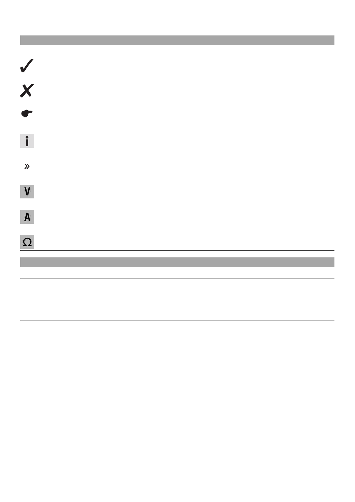
–Position the front fender. Mount and tighten screws 2.
Guideline
Remaining screws, chassis M6 10 Nm (7.4 lbf ft)
3.6 Refueling
Danger
Fire hazard Fuel is highly flammable.
–Never refuel the vehicle near open flames or burning cigarettes, and always switch off the engine first. Be careful that no
fuel is spilt, especially on hot vehicle components. Clean up spilt fuel immediately.
–The fuel in the fuel tank expands when warm and may emerge if overfilled. Follow the instructions on refueling.
Warning
Danger of poisoning Fuel is poisonous and a health hazard.
–Fuel must not come into contact with the skin, eyes, or clothing. Do not breathe in the fuel vapors. If contact occurs with
the eyes, rinse with water immediately and contact a physician. Immediately clean contaminated areas on the skin with
soap and water. If fuel is swallowed, contact a physician immediately. Change clothing that is contaminated with fuel.
Warning
Environmental hazard Improper handling of fuel is a danger to the environment.
–Do not allow fuel to get into the ground water, the ground, or the sewage system.
–Switch off the engine.
–Open the filler cap. ( p. 6)
AA
400382-10
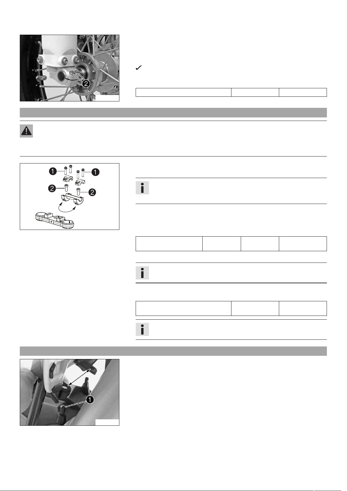
–Fill the fuel tank with fuel up to measurement A.
Guideline
Measurement of A35 mm (1.38 in)
Fuel tank capac-
ity, approx.
3.5 l (3.7 qt.) Super unleaded gasoline (95 octane),
mixed with 2-stroke engine oil (1:60)
( p. 9)
2-stroke engine oil ( p. 9)
–Close the filler cap. ( p. 7)
3.7 Opening the filler cap
Danger
Fire hazard Fuel is highly flammable.
–Never refuel the vehicle near open flames or burning cigarettes, and always switch off the engine first. Be careful that no
fuel is spilt, especially on hot vehicle components. Clean up spilt fuel immediately.
–The fuel in the fuel tank expands when warm and may emerge if overfilled. Follow the instructions on refueling.
Warning
Danger of poisoning Fuel is poisonous and a health hazard.
–Fuel must not come into contact with the skin, eyes, or clothing. Do not breathe in the fuel vapors. If contact occurs with
the eyes, rinse with water immediately and contact a physician. Immediately clean contaminated areas on the skin with
soap and water. If fuel is swallowed, contact a physician immediately. Change clothing that is contaminated with fuel.
Store fuel properly in a suitable canister and keep away from children.
Warning
Environmental hazard Improper handling of fuel is a danger to the environment.
–Do not allow fuel to get into the ground water, the ground, or the sewage system.

3 WORK 7
602661-10
–Press release button 1, turn the filler cap counterclockwise, and lift it free.
3.8 Closing the filler cap
602662-10
–Replace the filler cap and turn clockwise until the release button 1locks in place.
Info
Run the fuel tank breather hose 2without kinks.

4 TECHNICAL DATA - TIGHTENING TORQUES FOR CHASSIS 8
Spoke nipple M3.5 3 Nm (2.2 lbf ft) –
Remaining nuts, chassis M6 10 Nm (7.4 lbf ft) –
Remaining screws, chassis M6 10 Nm (7.4 lbf ft) –
Screw, ball joint of push rod on foot
brake cylinder
M6 10 Nm (7.4 lbf ft) –
Screw, foot brake cylinder M6 10 Nm (7.4 lbf ft) –
Screw, fork stub M6 10 Nm (7.4 lbf ft) –
Screw, front brake disc M6 14 Nm (10.3 lbf ft) Loctite®243™
Screw, rear brake disc M6 14 Nm (10.3 lbf ft) Loctite®243™
Screw, throttle grip M6 4.5 Nm (3.32 lbf ft) –
Nut, rim lock M8 10 Nm (7.4 lbf ft) –
Remaining nuts, chassis M8 25 Nm (18.4 lbf ft) –
Remaining screws, chassis M8 25 Nm (18.4 lbf ft) –
Screw, bottom triple clamp M8 15 Nm (11.1 lbf ft) –
Screw, brake caliper M8 20 Nm (14.8 lbf ft) Loctite®243™
Screw, engine bracket M8 30 Nm (22.1 lbf ft) –
Screw, handlebar clamp M8 20 Nm (14.8 lbf ft) –
Screw, rear sprocket M8 25 Nm (18.4 lbf ft) Loctite®243™
Screw, tail piece M8 35 Nm (25.8 lbf ft) Loctite®243™
Screw, top triple clamp M8 20 Nm (14.8 lbf ft) –
Remaining nuts, chassis M10 45 Nm (33.2 lbf ft) –
Remaining screws, chassis M10 45 Nm (33.2 lbf ft) –
Screw, bottom shock absorber M10 45 Nm (33.2 lbf ft) –
Screw, foot brake lever M10 35 Nm (25.8 lbf ft) Loctite®243™
Screw, front wheel spindle M10 40 Nm (29.5 lbf ft) –
Screw, handlebar support M10 40 Nm (29.5 lbf ft) Loctite®243™
Screw, top shock absorber M10 45 Nm (33.2 lbf ft) –
Nut, rear wheel spindle M12x1 40 Nm (29.5 lbf ft) –
Nut, swingarm pivot M12x1 40 Nm (29.5 lbf ft) –
Nut, steering stem M20x1.5 10 Nm (7.4 lbf ft) –

5 SUBSTANCES 9
2-stroke engine oil
According to
–JASO FC ( p. 11)
Guideline
–Only use high quality 2-stroke engine oil of a well-known brand. KTM recommends Motorex®products.
Fully synthetic
Supplier
Motorex®
–Cross Power 2T
Super unleaded (ROZ 95/RON 95/PON 91)
According to
–DIN EN 228 (ROZ 95/RON 95/PON 91)
Guideline
–Only use unleaded super fuel that matches or is equivalent to the specified fuel grade.
–Fuel with an ethanol content of up to 10 % (E10 fuel) is safe to use.
Info
Do not use fuel containing methanol (e. g. M15, M85, M100) or more than 10 % ethanol (e. g. E15, E25, E85, E100).
Super unleaded gasoline (95 octane), mixed with 2-stroke engine oil (1:60)
According to
–DIN EN 228
–JASO FC ( p. 11) (1:60)
Mixture ratio
1:60 2-stroke engine oil ( p. 9)
Super unleaded (ROZ 95/RON 95/PON 91) ( p. 9)
Supplier
Motorex®
–Cross Power 2T

6 AUXILIARY SUBSTANCES 10
Long-life grease
Guideline
–KTM recommends Motorex®products.
Supplier
Motorex®
–Bike Grease 2000

7 STANDARDS 11
JASO FC
JASO FC is a classification for a 2-stroke engine oil that was specifically developed for the extreme demands of racing. Thanks to first
rate synthetic esters and specially designed additives, superb combustion is achieved even under extreme operating conditions.

*3213088en*
3213088en
08/2013
KTM-Sportmotorcycle AG
5230 Mattighofen/Austria
http://www.ktm.com
Photo: Mitterbauer/KTM
Table of contents
Other KTM Motorcycle manuals

KTM
KTM 250 XC-F 2012 Manual

KTM
KTM 690 Enduro R User manual

KTM
KTM 65 SX 2009 Operating instructions

KTM
KTM 450 Rally Factory Replica 2014 User manual

KTM
KTM 2004 660 SMC User manual

KTM
KTM 50 SX PRO SENIOR LC User manual

KTM
KTM 85 SX 2017 Manual

KTM
KTM ENDURO 640 LC4 User manual

KTM
KTM 390 Duke Series 2019 User manual

KTM
KTM Freeride E-XC 2018 User manual

KTM
KTM F8101S5 User manual

KTM
KTM 500 EXC AUS User manual

KTM
KTM 450 SMR 2021 Manual

KTM
KTM 200 Duke 2016 User manual

KTM
KTM 300 SX User guide

KTM
KTM 350 SX-F 2021 User manual

KTM
KTM 125 Duke EU 2012 Manual

KTM
KTM 990 ADVENTURE R EU User manual

KTM
KTM 400 EXC EU 2011 Manual

KTM
KTM 990 Adventure AUS/UK User manual