KTM 2011 690 SMC EU Operating instructions

REPAIR MANUAL 2011
690 SMC EU
690 SMC AUS/UK
Art. no. 3206122en


INTRODUCTION 1
INTRODUCTION
Read this repair manual carefully and thoroughly before beginning work.
This vehicle can only fulfill the demands placed on it in the long run if the specified service work is performed regularly by qualified
experts.
The repair manual was written to correspond to the most current state of this model series. We reserve the right to make changes in
the interest of technical advancement without, at the same time, updating this repair manual.
We shall not provide a description of general workshop methods. Likewise, safety rules that apply in a workshop are not specified here.
It is assumed that repair work will be performed by a fully trained mechanic.
All specifications are non-binding. KTM Sportmotorcycle AG specifically reserves the right to modify or delete technical specifica-
tions, prices, colors, forms, materials, services, designs, equipment, etc., without prior notice and without specifying reasons, to adapt
these to local conditions, as well as to stop production of a particular model without prior notice. KTM accepts no liability for delivery
options, deviations from illustrations and descriptions, as well as misprints and other errors. The models portrayed partly contain spe-
cial equipment that does not belong to the regular scope of supply.
© 2013 KTM-Sportmotorcycle AG, Mattighofen Austria
All rights reserved
Reproduction, even in part, as well as copying of all kinds, is permitted only with the express written permission of the copyright
owner.
ISO 9001(12 100 6061)
According to the international quality management standard ISO 9001, KTM uses quality assurance processes that lead
to the maximum possible quality of the products.
Issued by: TÜV Management Service
KTM-Sportmotorcycle AG
5230 Mattighofen, Austria

TABLE OF CONTENTS 2
TABLE OF CONTENTS
1 MEANS OF REPRESENTATION ..................................... 5
1.1 Symbols used ................................................... 5
1.2 Formats used.................................................... 5
2 SAFETY ADVICE........................................................... 6
2.1 Repair Manual .................................................. 6
2.2 Safety advice.................................................... 6
2.3 Degrees of risk and symbols ............................... 6
2.4 Work rules........................................................ 6
3 IMPORTANT NOTES..................................................... 7
3.1 Guarantee, warranty .......................................... 7
3.2 Operating and auxiliary substances ..................... 7
3.3 Spare parts, accessories .................................... 7
3.4 Figures ............................................................ 7
4 SERIAL NUMBERS ...................................................... 8
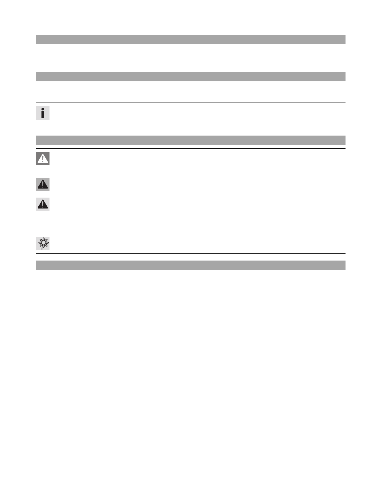
4.1 Chassis number ................................................ 8
4.2 Type label ........................................................ 8
4.3 Engine number ................................................. 8
4.4 Key number...................................................... 8
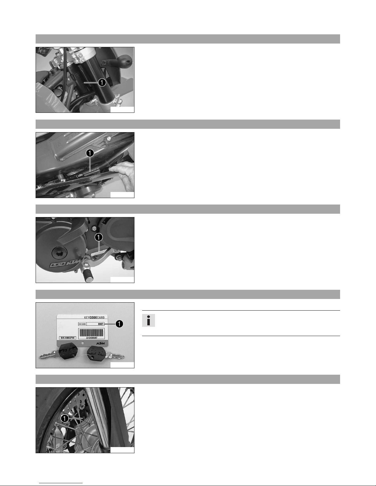
4.5 Fork part number .............................................. 8
4.6 Shock absorber part number .............................. 9
5 MOTORCYCLE ........................................................... 10
5.1 Raising the motorcycle with the rear wheel
stand ............................................................. 10
5.2 Taking the motorcycle off of the rear wheel
stand ............................................................. 10
5.3 Raising the motorcycle with the front wheel
stand ............................................................. 10
5.4 Taking the motorcycle off of the front wheel
stand ............................................................. 10
5.5 Raising the motorcycle with the lift stand.......... 11
5.6 Removing the motorcycle from the lift stand...... 11
5.7 Raising the motorcycle with the work stand ....... 11
5.8 Removing the motorcycle from the work stand ... 12
5.9 Starting.......................................................... 12
5.10 Starting the motorcycle to make checks ............ 13
6 FORK, TRIPLE CLAMP ............................................... 14
6.1 Adjusting the compression damping of the
fork ............................................................... 14
6.2 Adjusting the rebound damping of the fork ........ 14
6.3 Bleeding the fork legs...................................... 14
6.4 Cleaning the dust boots of the fork legs............. 15
6.5 Removing the fork protector ............................. 15
6.6 Installing the fork protector.............................. 15
6.7 Removing fork legs.......................................... 16
6.8 Installing the fork legs..................................... 17
6.9 Servicing the fork............................................ 18
6.10 Disassembling the fork legs.............................. 19
6.11 Checking the fork legs ..................................... 22
6.12 Assembling the fork legs.................................. 23
6.13 Checking the steering head bearing play............ 27
6.14 Adjusting the steering head bearing play ........... 28
7 HANDLEBAR, CONTROLS........................................... 29
7.1 Handlebar position.......................................... 29
7.2 Adjusting handlebar position............................ 29
7.3 Checking the routing of the throttle cable.......... 29
7.4 Checking the play in the throttle cable .............. 30
7.5 Adjusting the play in the throttle cable.............. 30
8 SHOCK ABSORBER, SWINGARM ................................ 32
8.1 Adjusting the high-speed compression
damping of the shock absorber......................... 32
8.2 Adjusting the low-speed compression damping
of the shock absorber ...................................... 32
8.3 Adjusting the rebound damping of the shock
absorber......................................................... 33
8.4 Measuring the unloaded rear wheel sag ............. 33
8.5 Checking the static sag of the shock absorber.... 33
8.6 Checking the riding sag of the shock absorber.... 34
8.7 Adjusting the spring preload of the shock
absorber......................................................... 34
8.8 Adjusting the riding sag................................... 35
8.9 Removing the shock absorber........................... 35
8.10 Installing the shock absorber............................ 36
8.11 Servicing the shock absorber............................ 38
8.12 Removing the spring........................................ 38
8.13 Dismantling the damper .................................. 39
8.14 Disassembling the piston rod ........................... 40
8.15 Checking the damper ...................................... 41
8.16 Removing the heim joint.................................. 42
8.17 Installing the heim joint................................... 43
8.18 Assembling the piston rod................................ 44
8.19 Assembling the damper ................................... 45
8.20 Bleeding and filling the damper ....................... 47
8.21 Filling the damper with nitrogen....................... 49
8.22 Installing the spring ........................................ 50
9 EXHAUST.................................................................. 52
9.1 Removing the manifold.................................... 52
9.2 Installing the manifold .................................... 53
9.3 Removing the main silencer ............................. 54
9.4 Installing the main silencer.............................. 54
10 AIR FILTER ............................................................... 56
10.1 Removing the air filter..................................... 56
10.2 Installing the air filter...................................... 56
10.3 Removing the air filter box............................... 56
10.4 Installing the air filter box................................ 57
11 FUEL TANK, SEAT, TRIM ........................................... 59
11.1 Opening the filler cap...................................... 59
11.2 Closing filler cap............................................. 59
11.3 Removing the seat .......................................... 59
11.4 Mounting the seat........................................... 60
11.5 Taking off the side cover.................................. 60
11.6 Mounting the side cover................................... 60
11.7 Checking the fuel pressure............................... 60
11.8 Changing the fuel filter.................................... 61
11.9 Changing the fuel pump .................................. 64
12 WHEELS ................................................................... 68
12.1 Checking the tire air pressure........................... 68
12.2 Checking the tire condition .............................. 68
12.3 Checking the brake discs ................................. 69
12.4 Checking the spoke tension.............................. 69
12.5 Checking the rim run-out ................................. 70
12.6 Front wheel .................................................... 70
12.6.1 Removing front wheel.................................. 70
12.6.2 Installing the front wheel............................. 71
12.6.3 Removing the brake disc of the front brake.... 72
12.6.4 Installing the brake disc of the front brake .... 72
12.7 Rear wheel ..................................................... 72
12.7.1 Removing rear wheel ................................... 72
12.7.2 Installing the rear wheel .............................. 73
12.7.3 Removing the brake disc of the rear brake..... 73
12.7.4 Installing the brake disc of the rear brake...... 74
12.7.5 Checking the chain tension.......................... 74
12.7.6 Adjusting the chain tension ......................... 74
12.7.7 Adjusting chain guide.................................. 75

TABLE OF CONTENTS 3
12.7.8 Checking the chain, rear sprocket, engine
sprocket, and chain guide............................ 75
12.7.9 Cleaning the chain...................................... 77
12.7.10 Checking the rear hub rubber dampers.......... 77
13 WIRING HARNESS, BATTERY..................................... 79
13.1 Removing the battery ...................................... 79
13.2 Installing the battery ....................................... 79
13.3 Disconnecting the battery ................................ 79
13.4 Connecting the battery .................................... 80
13.5 Recharging the battery .................................... 80
13.6 Checking the charging voltage.......................... 81
13.7 Changing the main fuse................................... 82
13.8 Changing fuses of individual power
consumers...................................................... 82
13.9 Adjusting the engine characteristic ................... 83
14 BRAKE SYSTEM ........................................................ 85
14.1 Checking the front brake linings ....................... 85
14.2 Changing the brake linings of the front brake..... 85
14.3 Adjusting the basic position of the hand brake
lever .............................................................. 86
14.4 Checking the front brake fluid level .................. 86
14.5 Adding front brake fluid................................... 87
14.6 Changing the front brake fluid.......................... 88
14.7 Checking the rear brake linings ........................ 88
14.8 Changing the rear brake linings ........................ 89
14.9 Checking the free travel of foot brake lever ........ 90
14.10 Adjusting the basic position of the foot brake
lever .............................................................. 91
14.11 Checking rear brake fluid level ......................... 91
14.12 Adding rear brake fluid.................................... 92
14.13 Changing the rear brake fluid ........................... 92
15 LIGHTING SYSTEM, INSTRUMENTS ........................... 94
15.1 Combination instrument .................................. 94
15.1.1 Setting kilometers or miles .......................... 94
15.1.2 Setting the clock ........................................ 94
15.1.3 Setting/resetting display TRIP 1 ................... 94
15.1.4 Setting/resetting display TRIP 2 ................... 94
15.1.5 Setting the wheel circumference .................. 95
15.2 Checking the headlight setting ......................... 96
15.3 Adjusting the headlight range........................... 96
15.4 Removing the headlight mask with the
headlight........................................................ 96
15.5 Installing the headlight mask with the
headlight........................................................ 97
15.6 Changing the parking light bulb........................ 97
15.7 Changing the headlight bulb ............................ 98
15.8 Changing the turn signal bulb .......................... 99
16 ENGINE .................................................................. 100
16.1 Removing the engine..................................... 100
16.2 Installing the engine...................................... 102
16.3 Engine disassembly....................................... 106
16.3.1 Clamping the engine into the engine
assembly stand......................................... 106
16.3.2 Draining the engine oil .............................. 106
16.3.3 Removing starter motor ............................. 106
16.3.4 Removing valve cover ................................ 107
16.3.5 Removing the alternator cover .................... 107
16.3.6 Removing spacer ...................................... 107
16.3.7 Removing gear position sensor ................... 107
16.3.8 Removing oil filter .................................... 108
16.3.9 Removing thermostat ................................ 108
16.3.10 Setting engine to ignition top dead center ... 108
16.3.11 Removing water pump wheel...................... 109
16.3.12 Removing clutch cover .............................. 109
16.3.13 Removing spacer and spring ...................... 109
16.3.14 Removing spark plug................................. 110
16.3.15 Removing timing chain tensioner................ 110
16.3.16 Removing camshafts ................................. 110
16.3.17 Removing cylinder head ............................ 110
16.3.18 Removing piston....................................... 111
16.3.19 Removing rotor ......................................... 111
16.3.20 Removing timing chain rails....................... 112
16.3.21 Removing timing chain and timing chain
sprocket................................................... 112
16.3.22 Removing crankshaft position sensor .......... 112
16.3.23 Removing clutch cage ............................... 113
16.3.24 Removing primary gear.............................. 114
16.3.25 Removing starter drive............................... 114
16.3.26 Removing shift shaft ................................. 114
16.3.27 Removing shift drum locating..................... 114
16.3.28 Removing locking lever.............................. 115
16.3.29 Removing oil pumps.................................. 115
16.3.30 Removing left engine case ......................... 115
16.3.31 Removing crankshaft and balancer shaft ..... 116
16.3.32 Removing transmission shafts .................... 116
16.4 Work on individual parts ................................ 117
16.4.1 Work on the right section of the engine
case ........................................................ 117
16.4.2 Work on the left section of the engine
case ........................................................ 119
16.4.3 Work on the clutch cover ........................... 120
16.4.4 Removing crankshaft bearing inner ring ...... 121
16.4.5 Removing balancer shaft drive wheel .......... 121
16.4.6 Changing the connecting rod, conrod
bearing, and crank pin .............................. 121
16.4.7 Checking crankshaft run-out at bearing
pin .......................................................... 123
16.4.8 Installing balancer shaft drive wheel........... 123
16.4.9 Installing crankshaft bearing inner ring ....... 123
16.4.10 Measuring axial clearance of crankshaft
and balancer shaft .................................... 124
16.4.11 Cylinder - Nikasil®coating ......................... 124
16.4.12 Checking/measuring the cylinder ................ 125
16.4.13 Checking/measuring the piston................... 125
16.4.14 Checking piston ring end gap ..................... 126
16.4.15 Checking piston/cylinder mounting
clearance ................................................. 126
16.4.16 Checking oil pumps for wear ...................... 127
16.4.17 Replacing autodecompressor...................... 127
16.4.18 Preparing timing chain tensioner for
installation............................................... 128
16.4.19 Checking timing assembly ......................... 128
16.4.20 Removing rocker arm ................................ 129
16.4.21 Changing camshaft bearing........................ 129
16.4.22 Removing valves ....................................... 130
16.4.23 Checking valves ........................................ 130
16.4.24 Checking valve springs .............................. 131
16.4.25 Checking valve spring retainer.................... 131
16.4.26 Checking cylinder head ............................. 131
16.4.27 Installing valves........................................ 132
16.4.28 Installing rocker arm ................................. 133
16.4.29 Disassembling the antihopping clutch......... 133
16.4.30 Checking the clutch .................................. 133
16.4.31 Preassembling the antihopping clutch......... 135

TABLE OF CONTENTS 4
16.4.32 Checking shift mechanism......................... 136
16.4.33 Preassembling shift shaft .......................... 136
16.4.34 Disassembling the main shaft .................... 137
16.4.35 Dismantling countershaft........................... 137
16.4.36 Checking the transmission ......................... 138
16.4.37 Assembling the main shaft......................... 139
16.4.38 Assembling countershaft ........................... 140
16.4.39 Checking the starter drive .......................... 141
16.4.40 Removing freewheel .................................. 141
16.4.41 Checking freewheel................................... 142
16.4.42 Installing freewheel................................... 142
16.5 Engine assembly........................................... 143
16.5.1 Installing transmission shafts..................... 143
16.5.2 Installing crankshaft and balancer shaft...... 144
16.5.3 Installing left engine case.......................... 145
16.5.4 Installing oil pumps .................................. 145
16.5.5 Installing locking lever .............................. 146
16.5.6 Installing shift drum locating ..................... 146
16.5.7 Installing shift shaft.................................. 146
16.5.8 Installing starter drive ............................... 146
16.5.9 Installing primary gear............................... 147
16.5.10 Installing clutch cage................................ 147
16.5.11 Installing crankshaft position sensor ........... 148
16.5.12 Installing timing chain and timing chain
sprocket................................................... 149
16.5.13 Installing timing chain rails ....................... 149
16.5.14 Installing rotor.......................................... 149
16.5.15 Adjusting crankshaft position sensor
distance................................................... 150
16.5.16 Setting engine to top dead center............... 150
16.5.17 Installing piston........................................ 150
16.5.18 Installing cylinder head ............................. 152
16.5.19 Installing camshafts.................................. 152
16.5.20 Installing timing chain tensioner ................ 153
16.5.21 Checking valve clearance........................... 153
16.5.22 Adjusting valve clearance .......................... 154
16.5.23 Installing spark plug.................................. 155
16.5.24 Installing spacer and spring ....................... 155
16.5.25 Installing clutch cover............................... 155
16.5.26 Mounting water pump cover....................... 155
16.5.27 Installing thermostat ................................. 156
16.5.28 Installing the oil filter................................ 156
16.5.29 Installing gear position sensor .................... 156
16.5.30 Installing the spacer.................................. 157
16.5.31 Installing oil screens ................................. 157
16.5.32 Installing alternator cover .......................... 158
16.5.33 Installing starter motor .............................. 158
16.5.34 Installing valve cover................................. 159
16.5.35 Removing the engine from the engine
assembly stand......................................... 159
17 CLUTCH.................................................................. 160
17.1 Checking/rectifying the fluid level of the
hydraulic clutch............................................ 160
17.2 Changing the hydraulic clutch fluid ................ 160
18 WATER PUMP, COOLING SYSTEM ............................ 161
18.1 Draining the coolant...................................... 161
18.2 Filling/bleeding the cooling system ................. 161
18.3 Checking the antifreeze and coolant level........ 162
18.4 Checking the coolant level ............................. 163
19 LUBRICATION SYSTEM............................................ 164
19.1 Oil circuit..................................................... 164
19.2 Checking the engine oil level.......................... 164
19.3 Checking the engine oil pressure .................... 165
19.4 Changing the engine oil and filter, cleaning
the oil screens .............................................. 166
19.5 Draining the engine oil .................................. 166
19.6 Removing the oil filter ................................... 167
19.7 Installing the oil filter.................................... 167
19.8 Cleaning the oil screens................................. 168
19.9 Filling up with engine oil ............................... 169
19.10 Adding engine oil.......................................... 169
20 IGNITION SYSTEM................................................... 170
20.1 Alternator - checking the stator winding .......... 170
20.2 Checking the spark plug connector ................. 170
20.3 Ignition coil - checking the secondary
winding........................................................ 171
21 TECHNICAL DATA.................................................... 172
21.1 Engine ......................................................... 172
21.2 Engine tolerance, wear limits ......................... 172
21.3 Engine tightening torques .............................. 174
21.4 Capacities .................................................... 175
21.4.1 Engine oil ................................................ 175
21.4.2 Coolant .................................................... 175
21.4.3 Fuel ........................................................ 175
21.5 Chassis ........................................................ 175
21.6 Electrical system........................................... 176
21.7 Tires............................................................ 176
21.8 Fork............................................................. 177
21.9 Shock absorber............................................. 177
21.10 Chassis tightening torques ............................. 178
22 CLEANING/PROTECTIVE TREATMENT....................... 180
22.1 Cleaning the motorcycle ................................ 180
22.2 Checks and maintenance steps for winter
operation...................................................... 181
23 STORAGE................................................................ 182
23.1 Storage ........................................................ 182
23.2 Preparing for use after storage........................ 182
24 SERVICE SCHEDULE ............................................... 183
24.1 Service schedule........................................... 183
25 WIRING DIAGRAM ................................................... 186
25.1 Page 01 of 10 .............................................. 186
25.2 Page 02 of 10 .............................................. 188
25.3 Page 03 of 10 .............................................. 190
25.4 Page 04 of 10 .............................................. 192
25.5 Page 05 of 10 .............................................. 194
25.6 Page 06 of 10 .............................................. 196
25.7 Page 07 of 10 .............................................. 198
25.8 Page 08 of 10 .............................................. 200
25.9 Page 09 of 10 .............................................. 202
25.10 Page 10 of 10 .............................................. 204
26 SUBSTANCES ......................................................... 206
27 AUXILIARY SUBSTANCES ........................................ 208
28 SPECIAL TOOLS ...................................................... 210
29 STANDARDS ........................................................... 222
INDEX ............................................................................ 223

1 MEANS OF REPRESENTATION 5
1.1 Symbols used
The meaning of specific symbols is described below.
Indicates an expected reaction (e.g. of a work step or a function).
Indicates an unexpected reaction (e.g. of a work step or a function).
Indicates a page reference (more information is provided on the specified page).
Indicates information with more details or tips.
Indicates the result of a testing step.
Denotes a voltage measurement.
Denotes a current measurement.
Denotes a resistance measurement.
1.2 Formats used
The typographical formats used in this document are explained below.
Proprietary name Identifies a proprietary name.
Name®Identifies a protected name.
Brand™ Identifies a trademark.

2 SAFETY ADVICE 6
2.1 Repair Manual
Read this Repair Manual carefully and thoroughly before beginning work. It contains useful information and tips that will help you
repair and maintain your vehicle.
This manual assumes that the necessary special KTM tools and KTM workplace and workshop equipment are available.
2.2 Safety advice
A number of safety instructions need to be followed to operate the vehicle safely. Therefore, read this manual carefully. The safety
instructions are highlighted in the text and are referred to at the relevant passages.
Info
The vehicle has various information and warning labels at prominent locations. Do not remove information/warning labels. If
they are missing, you or others may not recognize dangers and may therefore be injured.
2.3 Degrees of risk and symbols
Danger
Identifies a danger that will immediately and invariably lead to fatal or serious permanent injury if the appropriate measures
are not taken.
Warning
Identifies a danger that is likely to lead to fatal or serious injury if the appropriate measures are not taken.
Caution
Identifies a danger that may lead to minor injuries if the appropriate measures are not taken.
Note
Identifies a danger that will lead to considerable machine and material damage if the appropriate measures are not taken.
Warning
Identifies a danger that will lead to environmental damage if the appropriate measures are not taken.
2.4 Work rules
Special tools are necessary for certain tasks. The tools are not contained in the vehicle but can be ordered under the number in paren-
theses. E.g.: bearing puller (15112017000)
During assembly, non-reusable parts (e.g. self-locking screws and nuts, seals and seal rings, O-rings, pins, lock washers) must be
replaced by new parts.
In some instances, a thread locker (e.g. Loctite®) is required. The manufacturer instructions for use must be followed.
After disassembly, clean the parts that are to be reused and check them for damage and wear. Change damaged or worn parts.
After you complete the repair or service work, check the operating safety of the vehicle.

3 IMPORTANT NOTES 7
3.1 Guarantee, warranty
The work prescribed in the service schedule must be carried out by an authorized KTM workshop only and confirmed in the customer's
Service & Warranty Booklet and in the KTM dealer.net; otherwise, all warranty claims will be void. No warranty claims can be consid-
ered for damage resulting from manipulations and/or alterations to the vehicle.
Additional information on the guarantee or warranty and the procedures involved can be found in the Service & Warranty Booklet.
3.2 Operating and auxiliary substances
Warning
Environmental hazard Improper handling of fuel is a danger to the environment.
–Do not allow fuel to get into the ground water, the ground, or the sewage system.
Use the operating and auxiliary substances (such as fuel and lubricants) as specified in the manual.
3.3 Spare parts, accessories
Only use spare parts and accessories approved and/or recommended by KTM. KTM accepts no liability for other products and any
resulting damage or loss.
The current KTM PowerParts for your vehicle can be found on the KTM website.
International KTM Website: http://www.ktm.com
3.4 Figures
The figures contained in the manual may depict special equipment.
In the interest of clarity, some components may be shown disassembled or may not be shown at all. It is not always necessary to dis-
assemble the component to perform the activity in question. Please follow the instructions in the text.

4 SERIAL NUMBERS 8
4.1 Chassis number
100217-10
The chassis number 1is stamped on the steering head on the right.
4.2 Type label
100218-10
Type label 1is located on the upper right frame tube below the seat.
4.3 Engine number
600479-10
The engine number 1is stamped on the left side of the engine under the engine
sprocket.
4.4 Key number
100179-10
The key number 1can be found on the KEYCODECARD.
Info
You need the key number to order a spare key. Keep the KEYCODECARD in a safe
place.
4.5 Fork part number
600480-10
The fork part number 1is stamped on the inner side of the fork stub.

4 SERIAL NUMBERS 9
4.6 Shock absorber part number
100216-10
The shock absorber part number 1is on the right of the shock absorber.

5 MOTORCYCLE 10
5.1 Raising the motorcycle with the rear wheel stand
Note
Danger of damage The parked vehicle may roll away or fall over.
–Always place the vehicle on a firm and even surface.
600492-01
–Insert the adapter into the rear wheel stand and screw into the swingarm on both
sides.
Adapter (61029055110) ( p. 212)
Rear wheel stand (61029055400) ( p. 213)
–Position the motorcycle upright, align the stand and raise the motorcycle.
5.2 Taking the motorcycle off of the rear wheel stand
Note
Danger of damage The parked vehicle may roll away or fall over.
–Always place the vehicle on a firm and even surface.
–Secure the motorcycle against falling over.
–Remove the rear wheel stand and lean the vehicle on the side stand.
5.3 Raising the motorcycle with the front wheel stand
Note
Danger of damage The parked vehicle may roll away or fall over.
–Always place the vehicle on a firm and even surface.
Preparatory work
–Raise the motorcycle with the rear wheel stand. ( p. 10)
600493-01
Main work
–Move the handlebar to the straight-ahead position. Align the front wheel stand with
the fork legs using the adapters.
Front wheel stand (61029055300) ( p. 212)
Info
Always raise the rear of the motorcycle first.
–Raise the front of the motorcycle.
5.4 Taking the motorcycle off of the front wheel stand
Note
Danger of damage The parked vehicle may roll away or fall over.
–Always place the vehicle on a firm and even surface.
–Secure the motorcycle against falling over.
–Remove the front wheel stand.

5 MOTORCYCLE 11
5.5 Raising the motorcycle with the lift stand
Note
Danger of damage The parked vehicle may roll away or fall over.
–Always place the vehicle on a firm and even surface.
S00053-10
–Raise the motorcycle using the underride guard under the motorcycle.
The wheels must no longer touch the ground.
–Secure the motorcycle against falling over.
5.6 Removing the motorcycle from the lift stand
Note
Danger of damage The parked vehicle may roll away or fall over.
–Always place the vehicle on a firm and even surface.
601873-11
–Remove the motorcycle from the lift stand and rest it on its side stand.
–Remove the lift stand.
5.7 Raising the motorcycle with the work stand
Note
Danger of damage The parked vehicle may roll away or fall over.
–Always place the vehicle on a firm and even surface.
300579-10
–Mount the special tool on the footrest.
Work stand adapter (75029036000) ( p. 215)
300201-10
–Position the motorcycle upright, align the special tool and raise the motorcycle.
Work stand (62529055000) ( p. 213)

5 MOTORCYCLE 12
5.8 Removing the motorcycle from the work stand
Note
Danger of damage The parked vehicle may roll away or fall over.
–Always place the vehicle on a firm and even surface.
300201-10
–Secure the motorcycle against falling over.
–Remove the work stand and lean the vehicle on the side stand.
300579-10
–Remove the special tool.
5.9 Starting
Danger
Danger of poisoning Exhaust gases are toxic and inhaling them may result in unconsciousness and/or death.
–When running the engine, always make sure there is sufficient ventilation, and do not start or run the engine in an enclosed
space without an effective exhaust extraction system.
Caution
Danger of accidents If the vehicle is operated with a discharged battery or without a battery, electronic components and safety
equipment may be damaged.
–Never operate the vehicle with a discharged battery or without a battery.
Note
Engine failure High engine speeds in cold engines have a negative effect on the service life of the engine.
–Always warm up the engine at low engine speeds.
B00103-10
–Turn the emergency OFF switch to the position .
–Switch on the ignition by turning the ignition key to position ON .
After you switch on the ignition, you can hear the fuel pump working for about
two seconds. The function check of the combination instrument is run at the
same time.
–Shift gear to neutral.
The green idling speed indicator lamp Nlights up.
–Press the electric starter button .

5 MOTORCYCLE 13
Info
Do not press the electric starter button until the combination instrument
function check is finished.
When starting, DO NOT open the throttle. If you open the throttle during the
starting procedure, fuel is not injected by the engine management system
and the engine cannot start.
Press the starter for a maximum of 5 seconds. Wait for at least 5 seconds
before trying again.
This motorcycle is equipped with a safety starting system. You can only start
the engine if the transmission is in neutral or if the clutch lever is pulled
when a gear is engaged. If the side stand is folded out and you shift into
gear and release the clutch lever, the engine stops.
–Take the weight off the side stand and swing it back up with your foot as far as it
will go.
5.10 Starting the motorcycle to make checks
Danger
Danger of poisoning Exhaust gases are toxic and inhaling them may result in unconsciousness and/or death.
–When running the engine, always make sure there is sufficient ventilation, and do not start or run the engine in an enclosed
space without an effective exhaust extraction system.
Info
Press the starter for a maximum of 5 seconds. Wait for a least 5 seconds before trying again.
B00103-10
–Turn the emergency OFF switch to the position .
–Shift gear to neutral.
–Switch on the ignition.
–Press the electric starter button .
Info
Do not open the throttle.

6 FORK, TRIPLE CLAMP 14
6.1 Adjusting the compression damping of the fork
Info
The hydraulic compression damping determines the fork suspension behavior.
600490-10
–Turn adjusting screws 1clockwise until they stop.
Info
The adjusting screws are located at the bottom end of the fork legs.
Make the same adjustment on both fork legs.
–Turn back counterclockwise by the number of clicks corresponding to the fork type.
Guideline
Compression damping
Comfort 20 clicks
Standard 15 clicks
Sport 10 clicks
Full payload 10 clicks
Info
Turn clockwise to increase damping; turn counterclockwise to reduce damp-
ing.
6.2 Adjusting the rebound damping of the fork
Info
The hydraulic rebound damping determines the fork rebound behavior.
100244-10
–Turn adjusting screws 1clockwise until they stop.
Info
The adjusting screws are located at the top end of the fork legs.
Make the same adjustment on both fork legs.
–Turn back counterclockwise by the number of clicks corresponding to the fork type.
Guideline
Rebound damping
Comfort 15 clicks
Standard 10 clicks
Sport 5 clicks
Full payload 5 clicks
Info
Turn clockwise to increase damping; turn counterclockwise to reduce damp-
ing.
6.3 Bleeding the fork legs
Preparatory work
–Lean the motorcycle on the side stand.
100844-10
Main work
–Briefly loosen bleeder screws 1.
Any excess pressure escapes from the interior of the fork.
–Mount and tighten bleeder screws.
Info
Carry out this action on both fork legs.

6 FORK, TRIPLE CLAMP 15
6.4 Cleaning the dust boots of the fork legs
Preparatory work
–Jack up the motorcycle and secure it against falling over.
The front wheel is no longer in contact with the ground and the fork legs are no
longer under tension.
–Remove the fork protector. ( p. 15)
L00350-10
Main work
–Push dust boot 1of both fork legs downwards.
Info
The dust boots should remove dust and coarse dirt particles from the fork
tubes. Over time, dirt can penetrate behind the dust boots. If this dirt is not
removed, the oil seals behind can start to leak.
Warning
Danger of accidents Reduced braking efficiency due to oil or grease on the
brake discs.
–Always keep the brake discs free of oil and grease, and clean them with
brake cleaner when necessary.
–Clean and oil the dust boots and inner fork tube of both fork legs.
Universal oil spray ( p. 209)
–Press the dust boots back into their normal position.
–Remove excess oil.
Finishing work
–Install the fork protector. ( p. 15)
–Remove the motorcycle from the lift stand. ( p. 11)
6.5 Removing the fork protector
600633-11
–Remove screws 1and take off clamp.
–Remove screws 2on left fork leg. Remove the fork protector.
–Remove the screws on the right fork leg. Remove the fork protector.
6.6 Installing the fork protector
600633-10
–Position the fork protection on the left fork leg. Mount and tighten screws 1.
Guideline
Remaining screws, chassis M6 10 Nm (7.4 lbf ft)
–Position the brake line and cable harness. Put the clamp on, mount and tighten
screws 2.
–Position the fork protection on the right fork leg. Mount and tighten the screws.
Guideline
Remaining screws, chassis M6 10 Nm (7.4 lbf ft)

6 FORK, TRIPLE CLAMP 16
6.7 Removing fork legs
Preparatory work
–Raise the motorcycle with the work stand. ( p. 11)
–Tie the rear of the vehicle down.
201374-10
Main work
–Remove screws 1and spacers 2.
–Press back the brake linings with a light lateral tilting of the brake caliper on the
brake disc. Carefully pull the brake caliper backwards from the brake disc.
Info
Do not pull the handbrake lever when the brake caliper is removed.
201375-10
–Loosen screws 3and 4.
–Unscrew screw 3about 6 turns and press your hand on the screw to push the
wheel spindle out of the axle clamp. Remove screw 3.
Warning
Danger of accidents Reduced braking effect caused by damaged brake
discs.
–Always lay the wheel down in such a way that the brake discs are not
damaged.
–Holding the front wheel, withdraw the wheel spindle. Take the front wheel out of
the fork.
201376-10
–Remove screws 5and the clamp. Take the brake line and wiring harness out of the
holder.
201377-10
–Remove the screws of the wheel speed sensor 6. Hang the wheel speed sensor to
one side.
201378-10
–Remove screws 7. Take off the fork protector.

6 FORK, TRIPLE CLAMP 17
201379-10
–Loosen the screws 8of the triple clamp. Remove the fork legs from the bottom.
6.8 Installing the fork legs
201379-11
–Slide the fork legs into the triple clamps on both sides.
Info
The bleeder screws must face forwards.
The topmost milled groove in the fork leg must be flush with the top edge of
the upper triple clamp.
The upper fork projection must be the same on both sides.
–Tighten screws 1on both sides.
Guideline
Screw, top triple clamp M8 17 Nm
(12.5 lbf ft)
Screw, bottom triple clamp M8 12 Nm (8.9 lbf ft)
201378-11
–Position the fork protection. Mount and tighten screws 2.
Guideline
Remaining screws, chassis M6 10 Nm (7.4 lbf ft)
201377-11
–Position the wheel speed sensor. Mount and tighten screws 3.
Guideline
Screw, wheel speed sensor M4 1 Nm
(0.7 lbf ft)
Loctite®243™
201376-11
–Position the brake line, wiring harness and clamp.
–Mount and tighten screws 4.

6 FORK, TRIPLE CLAMP 18
201380-10
Warning
Danger of accidents Reduced braking efficiency due to oil or grease on the
brake discs.
–Always keep the brake discs free of oil and grease, and clean them with
brake cleaner when necessary.
–Clean screw 5and the wheel spindle.
–Position the front wheel and insert the wheel spindle.
The brake linings are correctly positioned.
–Mount and tighten screw 5.
Guideline
Screw, front wheel spindle M24x1.5 45 Nm
(33.2 lbf ft)
201374-11
–Position the brake caliper and check that the brake linings are seated correctly.
–Mount screws 6spacers 7but do not tighten.
–Operate the hand brake lever repeatedly until the brake linings lie on the brake disc
and there is a pressure point. Fix the hand brake lever in the activated position.
The brake caliper straightens.
–Fully tighten screw 6.
Guideline
Screw, front brake caliper M10x1.25 45 Nm
(33.2 lbf ft)
Loctite®243™
–Remove the fixation of the hand brake lever.
–Unload the rear of the vehicle.
–Remove the motorcycle from the work stand. ( p. 12)
201375-11
–Pull the front brake and compress the fork powerfully a few times.
The fork legs straighten.
–Tighten screws 8.
Guideline
Screw, fork stub M8 15 Nm
(11.1 lbf ft)
6.9 Servicing the fork
Info
These operations are the same on both fork legs.
Condition
The fork legs have been removed.
Other manuals for 2011 690 SMC EU
1
This manual suits for next models
2
Table of contents
Other KTM Motorcycle manuals

KTM
KTM RC 390 2018 User manual

KTM
KTM 450 EXC RACING 2006 User manual

KTM
KTM 50 SUPERMOTO User manual

KTM
KTM 690 Duke USA User manual

KTM
KTM 125 Duke 2017 User manual

KTM
KTM Freeride E-XC 2019 Manual

KTM
KTM 450 Rally Factory Replica User manual

KTM
KTM 250 SX 2018 User manual

KTM
KTM 450 Rally Factory Replica 2014 User manual

KTM
KTM 625 SXC User manual