WORK 6
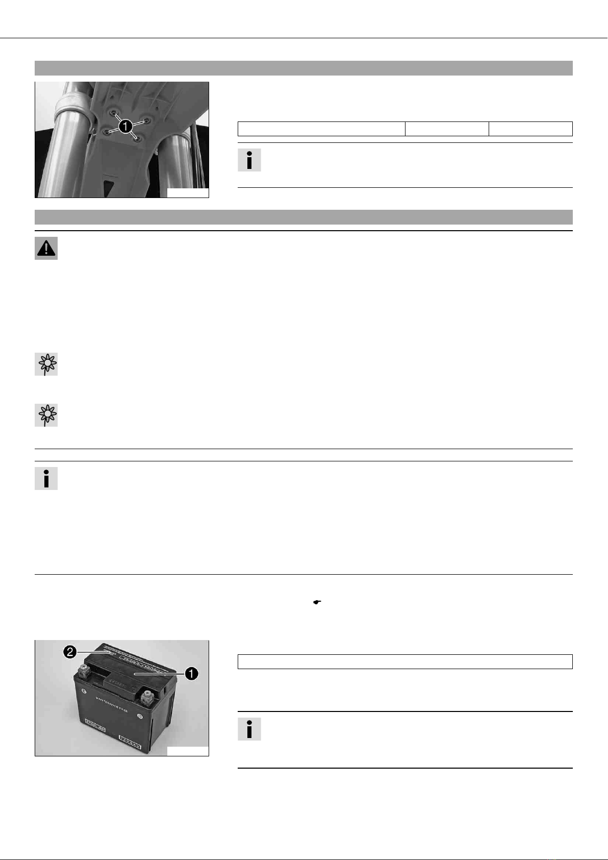
3.4Installing the front fender
600692-10
–Ensure that the spacing sleeves are mounted in the fender.
–Position the front fender. Mount and tighten screws .
Guideline
Remaining screws, chassis M6 10 Nm (7.4 lbf ft)
Info
Take care with the contact between the holding lugs and the start number
plate or headlight mask.
3.5Recharging the battery
Warning
Risk of injury Battery acid and battery gases cause serious chemical burns.
–Keep batteries out of the reach of children.
–Wear suitable protective clothing and goggles.
–Avoid contact with battery acid and battery gases.
–Keep the battery away from sparks or open fire. Charge only in well-ventilated rooms.
–In the event of skin contact, rinse with large amounts of water. If battery acid gets in the eyes, rinse with water for at least
15 minutes and contact a physician.
Warning
Environmental hazard Components and battery acid are a danger to the environment.
–Do not dispose of batteries in normal household waste. Take defective or used batteries to a battery recycling operator.
Warning
Environmental hazard Problem materials cause environmental damage.
–Dispose of oil, grease, filters, fuel, cleaning substances, brake fluid, batteries, etc., according to regulations.
Info
Even if there is no load on the battery, it loses power every day.
The charge state and the type of charge are very important for the service life of the battery.
Fast recharging with a high charge current shortens the battery's service life.
If the charge current, the charge voltage and the charge time are exceeded, electrolyte escapes through the breathing holes.
The battery capacity is then reduced.
If the battery is discharged from starting, it must be recharged immediately.
If it stands for a long time in a discharged state, the battery becomes over-discharged and sulfated, and then it is destroyed.
The battery is maintenance-free, i.e., the acid level does not have to be checked.
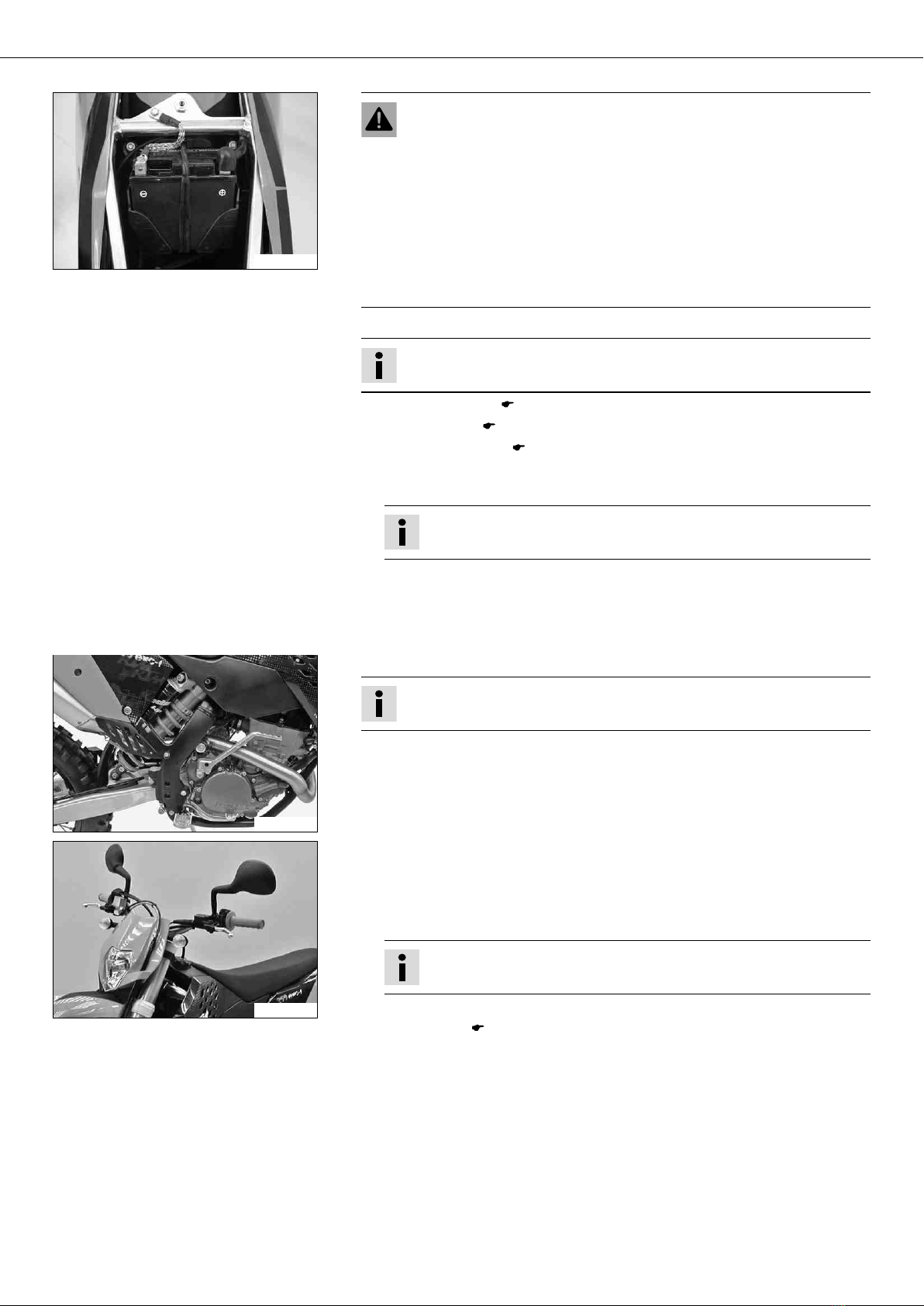
–Switch off all power consumers and switch off the engine.
–Remove the seat. ( p. 5)
–Disconnect the minus (negative) cable of the battery to avoid damage to the motor-
cycle's electronics.
400240-10
–Connect the battery charger to the battery. Switch on the battery charger.
Battery charger (58429074000)
You can also use the battery charger to test rest potential and start potential of the
battery, and to test the generator. With this device, you cannot overcharge the bat-
tery.
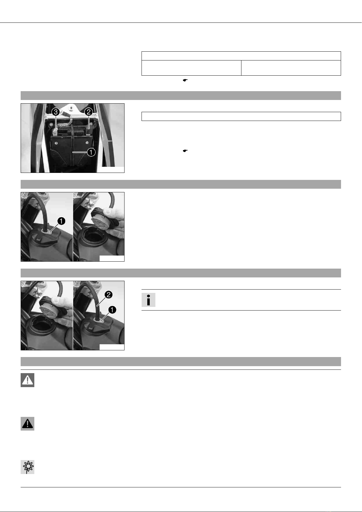
Info
Never remove the lid .
Charge the battery with at most 10% of the capacity specified on the bat-
tery .


 Supplementary service manual")