2 SETUP 3
2.1 Unpacking and setting up the vehicle
C00103-01
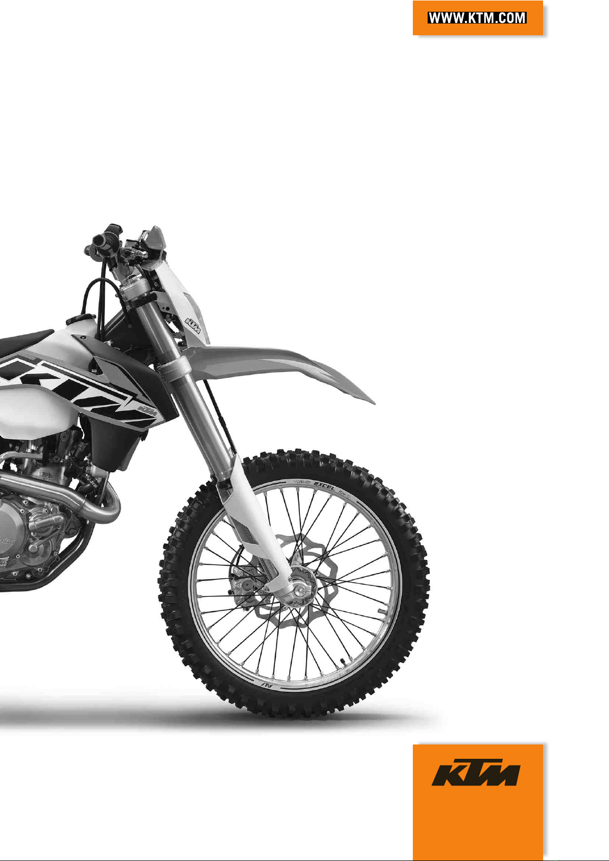
Packaging 2
–Remove the box and the plastic packaging.
Info
To avoid damaging the motorcycle during the setup, leave the protective
film on the vehicle until you have finished.
–Remove the separate enclosure and unpack it. Check that the scope of supply
is complete on the basis of the enclosed packing list.
–Have a lift stand available.
Lift stand (54829055000)
–Carefully loosen and remove the tension belt of the footrest mount.
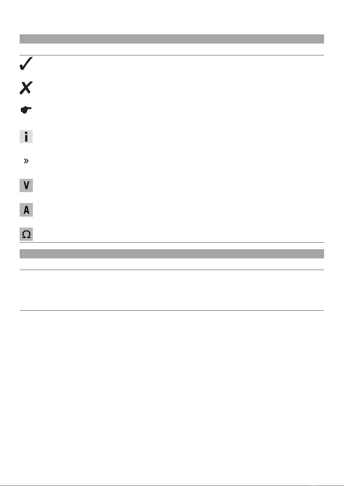
Info
An assistant prevents the motorcycle from falling over.
601706-01
–Together with an assistant, take the vehicle off the palette.
–Position the vehicle on a lift stand.
–Check the vehicle for transport damage.
–Remove the headlight mask with the headlight. ( p. 8)
C00104-01
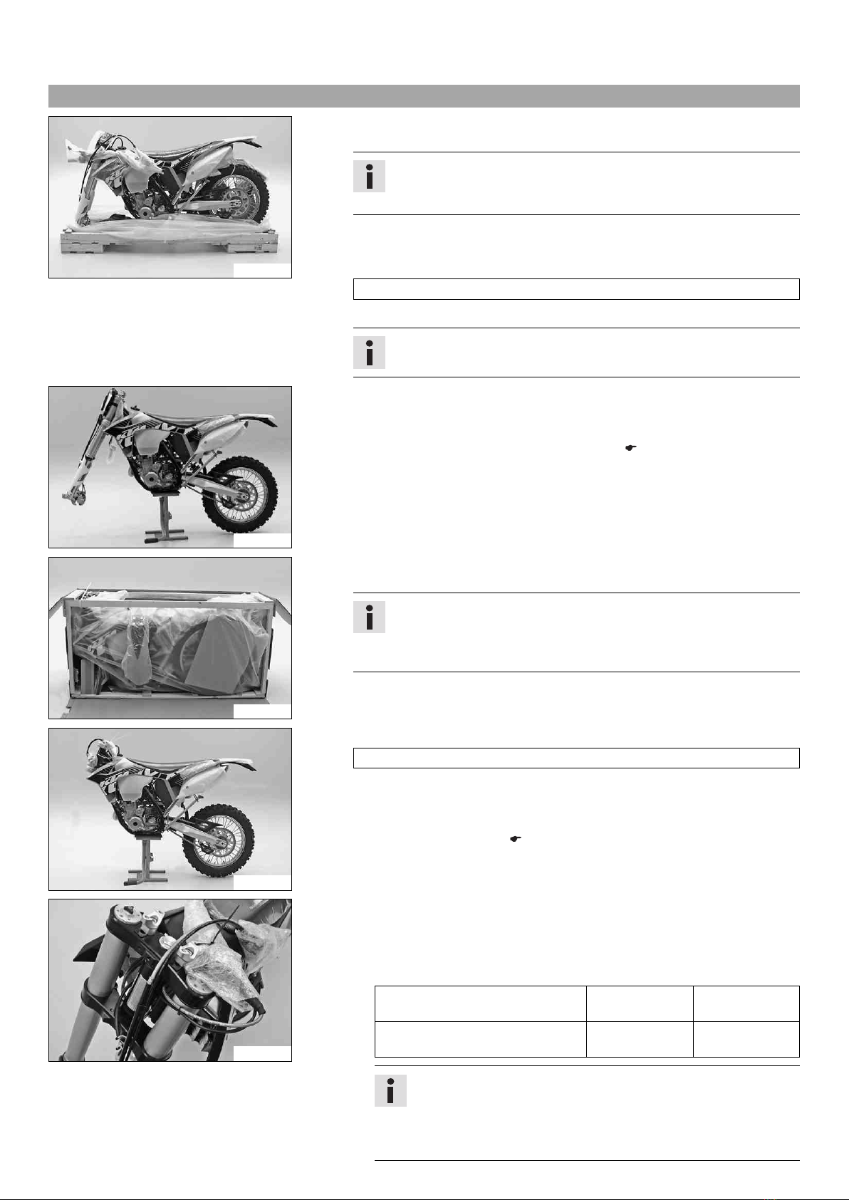
Package 12
–Remove the box and the plastic packaging.
Info
An assistant prevents the motorcycle from falling over.
To avoid damaging the motorcycle during the setup, leave the protective
film on the vehicle until you have finished.
–Remove the separate enclosure and unpack it. Check that the scope of supply
is complete on the basis of the enclosed packing list.
C00105-01
–Have a lift stand available.
Lift stand (54829055000)
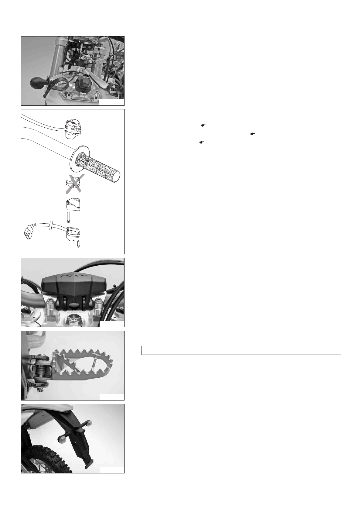
–Together with an assistant, take the vehicle off the palette.
–Position the vehicle on a lift stand.
–Check the vehicle for transport damage.
–Install the shock absorber. ( p. 10)
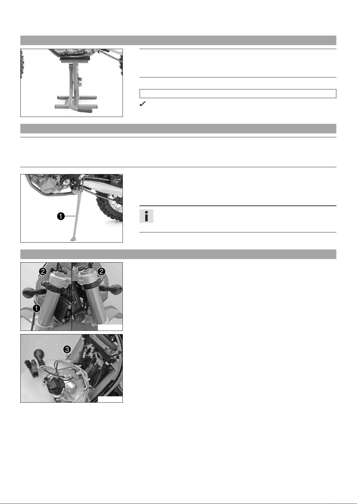
600814-01
–Route the clutch line with the clutch master cylinder toward the front between
the upper and lower triple clamps.
(EXC EU, EXC AUS, all XC‑W models, 500 EXC USA)
–Position the fork legs and tighten the screws of the triple clamp.
Guideline
Screw, top triple clamp M8 20 Nm
(14.8 lbf ft)
Screw, bottom triple clamp M8 15 Nm
(11.1 lbf ft)
Info
Grooves are milled into the side of the top end of the fork legs. The
second milled groove (from the top) in the fork leg must be flush
with the top edge of the upper triple clamp.
Position the bleeder screws toward the front.


 Supplementary service manual")