WORK 8
Info
Even when there is no load on the battery, it still loses power steadily.
The charge state and the type of charge are very important for the service life of the battery.
Rapid recharging with a high charging current shortens the battery's service life.
If the charging current, charging voltage, and charging time are exceeded, electrolyte escapes through the safety valves. This
reduces the battery capacity.
If the battery is depleted from starting the vehicle repeatedly, the battery must be charged immediately.
If the battery is left in a discharged state for an extended period, it will become over-discharged and sulfate, destroying the
battery.
The battery is maintenance-free, which means that the acid level does not need to be checked.
Preliminary work
–Switch off all power consumers and switch off the engine.
–Remove the seat. ( p. 7)
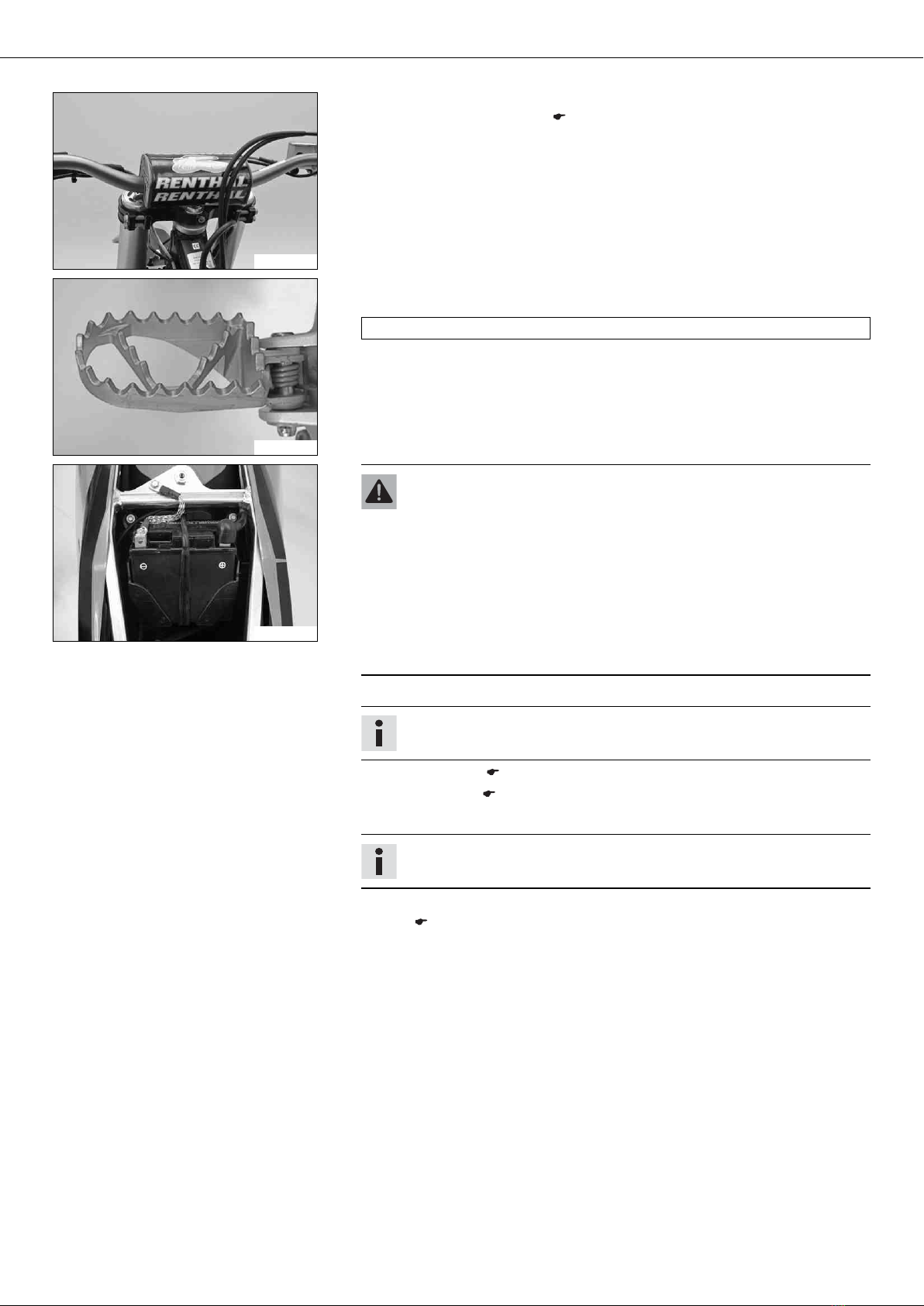
–Disconnect the negative cable of the battery to avoid damage to the onboard elec-
tronics.
400240-10
Main work
–Connect the battery charger to the battery. Switch on the battery charger.
Battery charger (58429074000)
You can also use the battery charger to test the open-circuit voltage and starting
voltage of the battery, and to test the alternator. With this device, you cannot over-
charge the battery.
Info
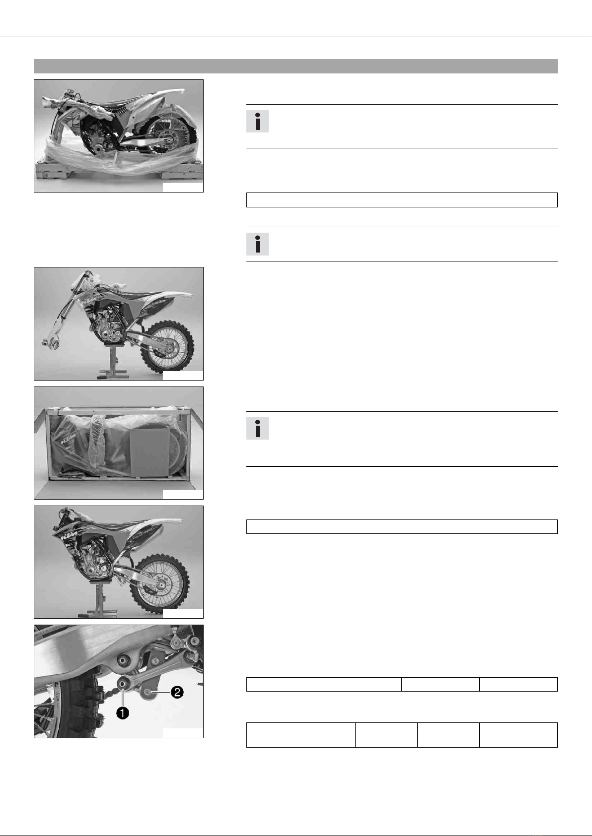
Never remove lid 1.
Charge the battery with a maximum of 10% of the capacity specified on
battery housing 2.
–Switch off the battery charger after charging. Disconnect the battery.
Guideline
The charge current, charge voltage, and charge time must not be exceeded.
Charge the battery regularly when the
motorcycle is not in use
3 months
Subsequent work
–Mount the seat. ( p. 7)
3.8Opening filler cap
Danger
Fire hazard Fuel is highly flammable.
–Never refuel the vehicle near open flames or burning cigarettes, and always switch off the engine first. Be careful that no
fuel is spilt, especially on hot vehicle components. Clean up spilt fuel immediately.
–Fuel in the fuel tank expands when warm and can escape if the tank is overfilled. See the notes on refueling.
Warning
Danger of poisoning Fuel is poisonous and a health hazard.
–Avoid contact between fuel and skin, eyes and clothing. Do not inhale fuel vapors. If fuel gets into your eyes, rinse immedi-
ately with water and contact a doctor. Wash affected skin areas immediately with soap and water. If fuel is swallowed, con-
tact a doctor immediately. Change clothing that has come into contact with fuel. Store fuel in a suitable canister according
to regulations and keep it out of the reach of children.
Warning
Environmental hazard Improper handling of fuel is a danger to the environment.
–Do not allow fuel to get into the ground water, the ground, or the sewage system.


 Supplementary service manual")