WORK 8
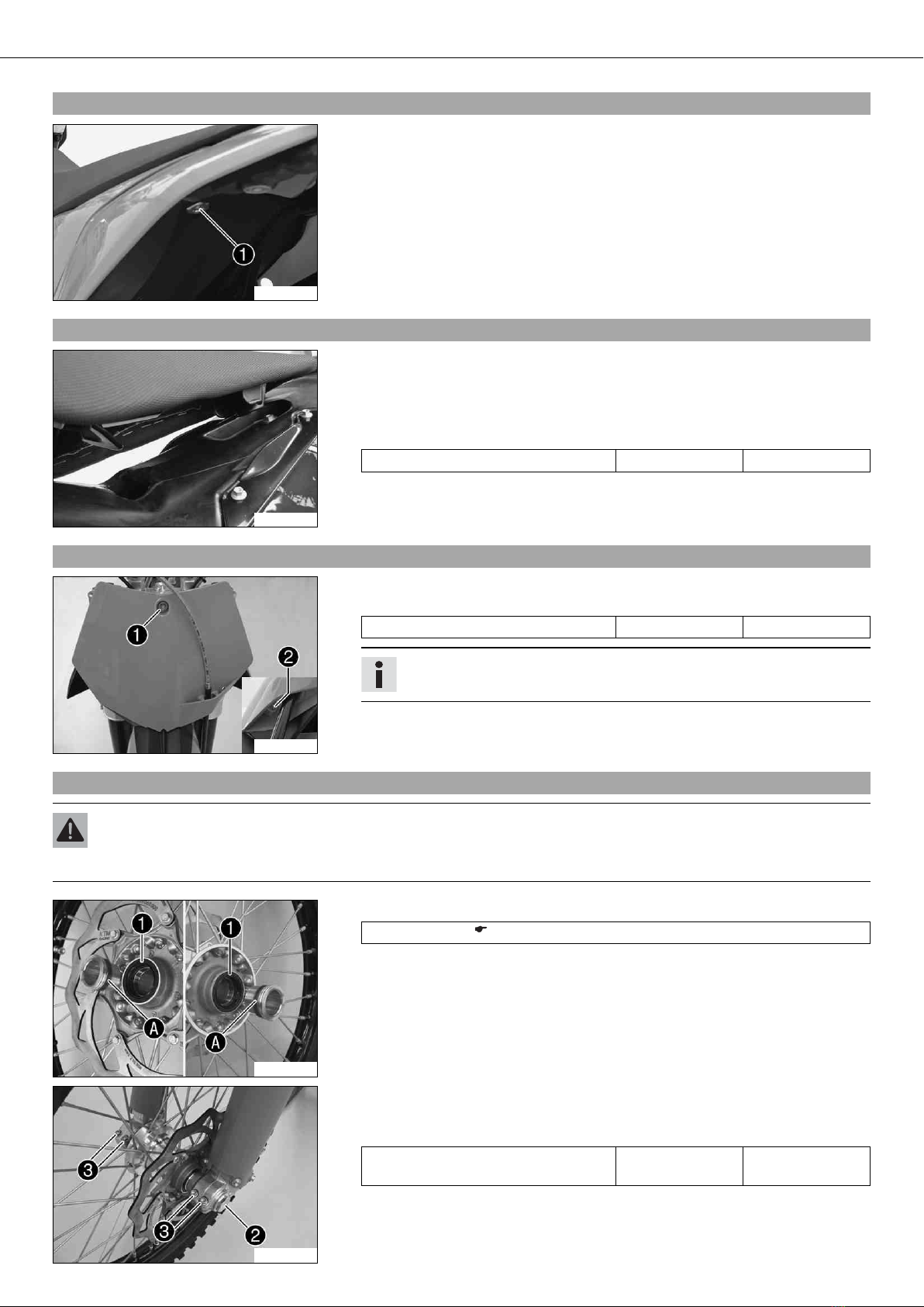
–Remove the motorcycle from the work stand.
–Pull the front wheel brake and push down hard on the fork several times to align
the fork legs.
–Fully tighten screw .
Guideline
Screw, fork stub M8 15 Nm
(11.1 lbf ft)
3.5Recharging the battery
Warning
Risk of injury Battery acid and battery gases cause serious cauterization.
–Keep batteries out of the reach of children.
–Wear suitable protective clothing and goggles.
–Avoid contact with battery acid and battery gases.
–Keep the battery away from sparks or open fire. Charge only in well ventilated rooms.
–In the event of skin contact, rinse with large amounts of water. If battery acid gets in the eyes, rinse with water for at least
15 minutes and contact a doctor.
Warning
Environmental hazard Battery parts and acid are harmful to the environment.
–Do not discard batteries with the household trash. Dispose of a defective battery in an environmentally compatible manner.
Give the battery to your KTM dealer or to a recycling center that accepts used batteries.
Warning
Environmental hazard Hazardous substances cause environmental damage.
–Oil, grease, filters, fuel, cleaners, brake fluid, etc., should be disposed of as stipulated in applicable regulations.
Info
Even if there is no load on the battery, it loses power every day.
The charge state and the type of charge are very important for the service life of the battery.
Fast recharging with a high charge current shortens the battery's service life.
If the charge current, the charge voltage and the charge time are exceeded, electrolyte escapes through the breathing holes.
The battery capacity is then reduced.
If the battery is discharged from starting, it must be recharged immediately.
If it stands for a long time in a discharged state, the battery becomes over-discharged and sulfated, and then it is destroyed.
The battery is maintenance-free, i.e., the acid level does not have to be checked.
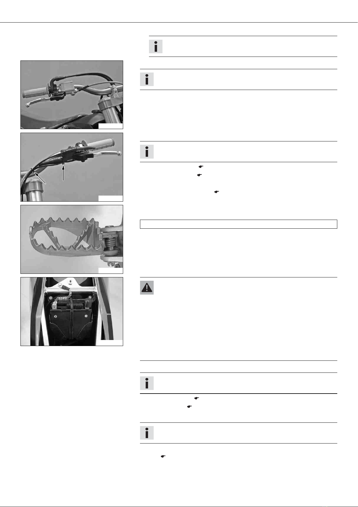
–Switch off all consumers and the engine.
–Remove the seat. ( p. 7)
–Disconnect the minus (negative) cable of the battery to avoid damage to the motor-
cycle's electronics.
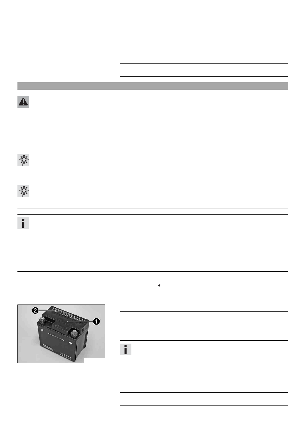
400240-10
–Connect the battery charger to the battery. Switch on the battery charger.
Battery charger (58429074000)
You can also use the battery charger to test the open-circuit voltage and cranking
power of the battery, and to test the generator. With this device, you cannot over-
charge the battery.
Info
Never remove the lid .
Charge the battery with at most 10% of the capacity specified on the bat-
tery .
–Switch off the charger after charging. Disconnect the battery.
Guideline
The charge current, charge voltage and charge time must not be exceeded.
Charge the battery regularly when the
motorcycle is not in use
3 months


 Supplementary service manual")