3 WORK 7
B00192-10
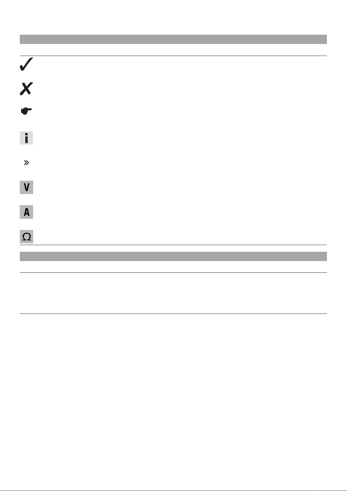
–Disconnect negative cable 3of the battery.
–Disconnect the positive (plus) cable 4of the battery.
–Take the battery 5out of the battery compartment.
Info
Never operate the motorcycle with a discharged battery or without a battery.
In both cases, electrical components and safety equipment can be dam-
aged. The vehicle is then no longer safe to ride.
3.4 Installing the battery
B00192-11
Main work
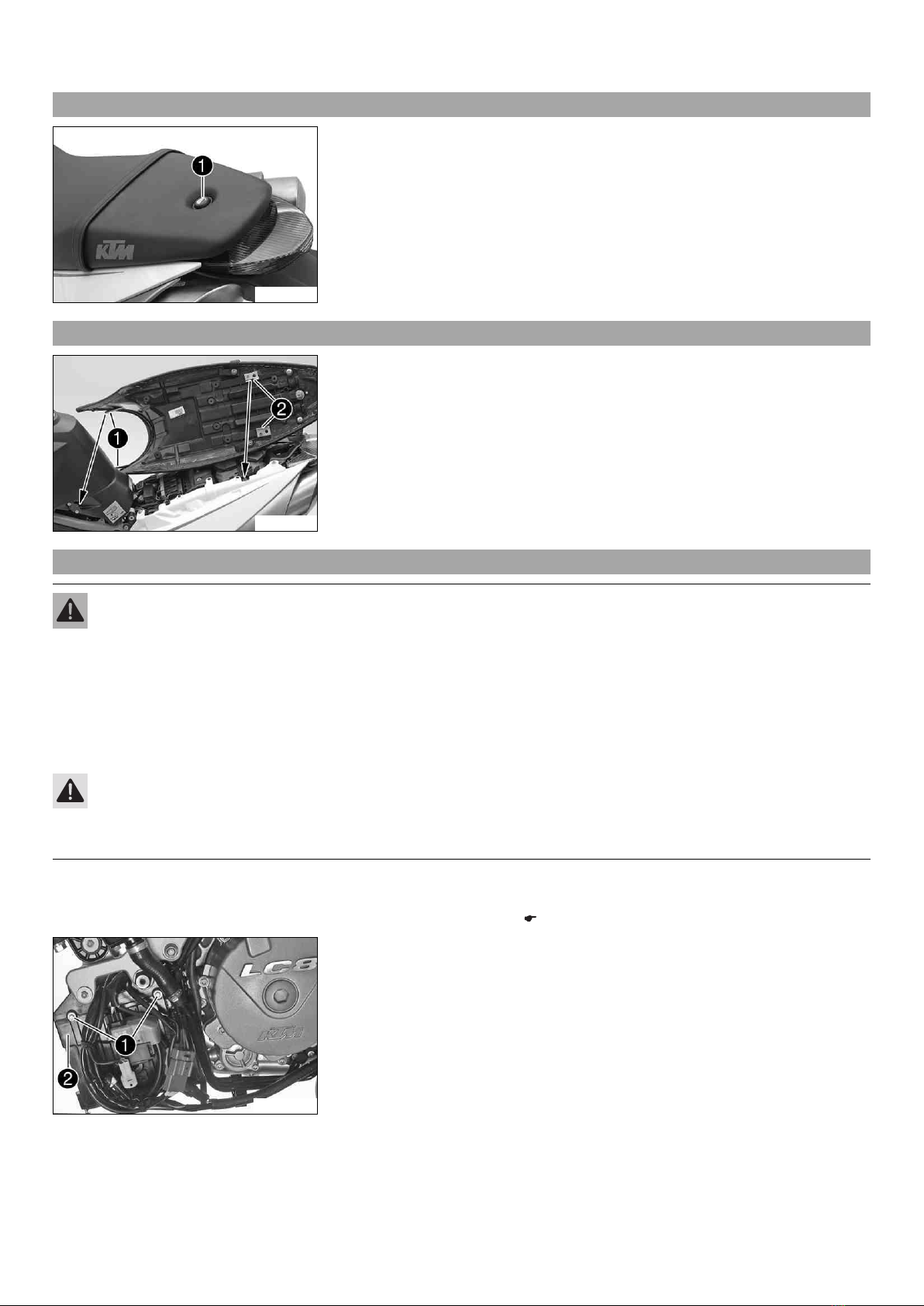
–Position the battery in the battery compartment.
–Connect positive cable 1.
–Connect negative cable 2.
B00191-11
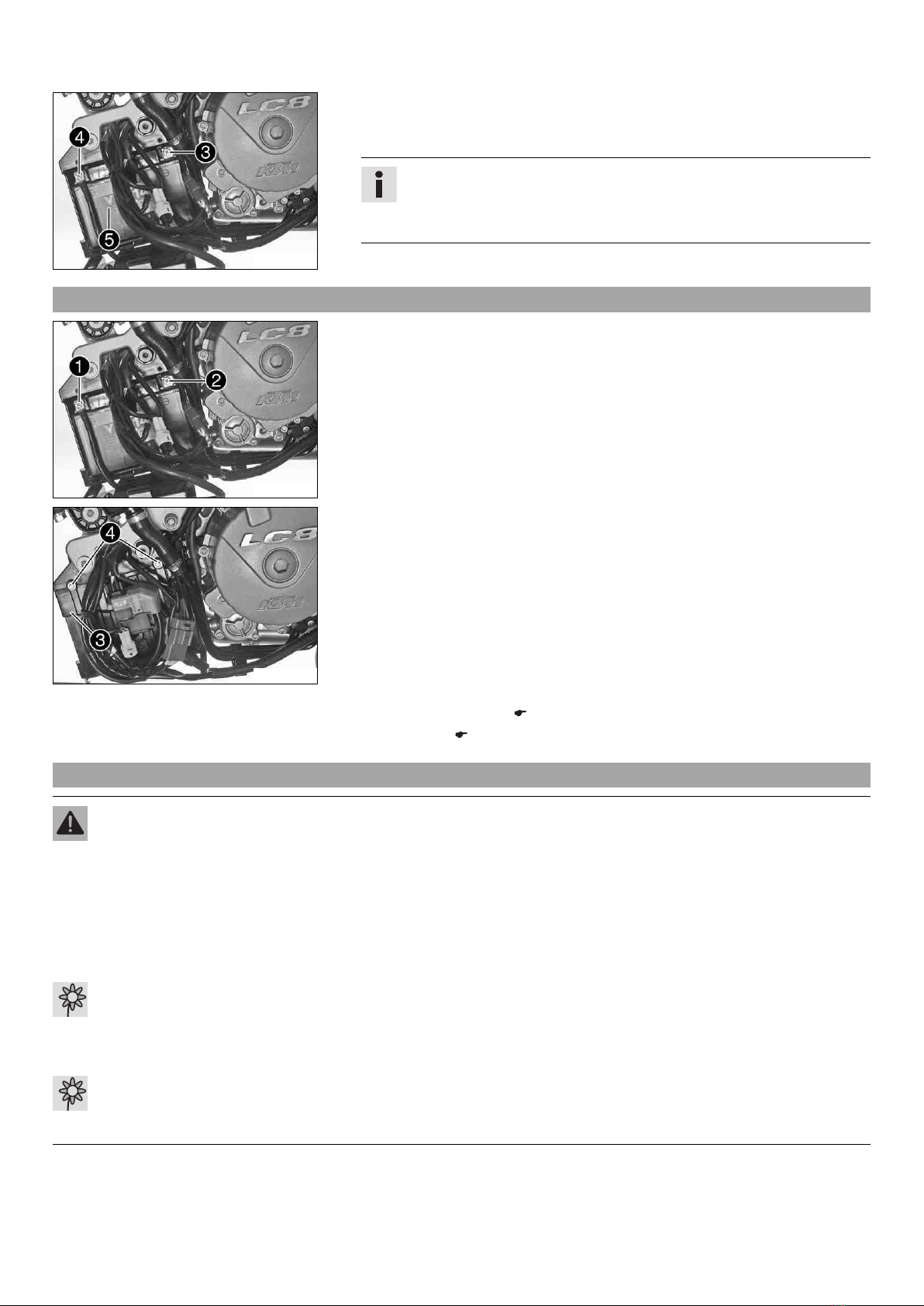
–Fold cover 3up.
–Mount and tighten screws 4.
–Attach the connector to the start relay.
–Position the wiring harness and fasten it with cable binders.
Finishing work
–Install the front spoiler. ( p. 9)
–Set the clock. ( p. 11)
3.5 Recharging the battery
Warning
Risk of injury Battery acid and battery gases cause serious chemical burns.
–Keep batteries out of the reach of children.
–Wear suitable protective clothing and goggles.
–Avoid contact with battery acid and battery gases.
–Keep sparks and open flames away from the battery. Only charge in well-ventilated rooms.
–In the event of skin contact, rinse with large amounts of water. If battery acid gets in the eyes, rinse with water for at least
15 minutes and contact a physician.
Warning
Environmental hazard The battery contains elements that are harmful to the environment.
–Do not discard batteries with the household waste. Dispose of faulty batteries in an environmentally compatible manner.
Give the battery to your authorized KTM dealer or dispose of it at a collection point for used batteries.
Warning
Environmental hazard Hazardous substances cause environmental damage.
–Oil, grease, filters, fuel, cleaners, brake fluid, etc., should be disposed of as stipulated in applicable regulations.


 Supplementary service manual")