3 WORK
8
3.8 Disconnecting the negative cable of the battery
Preparatory work
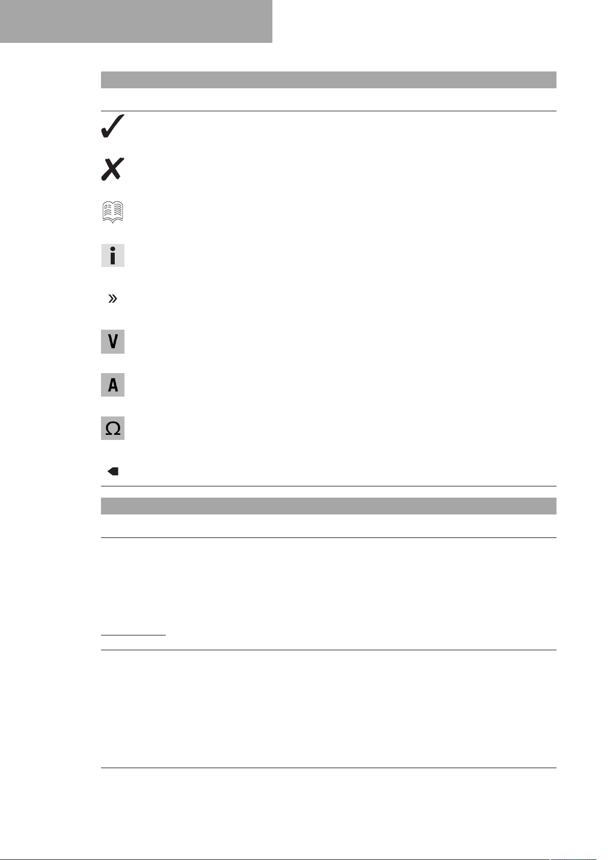
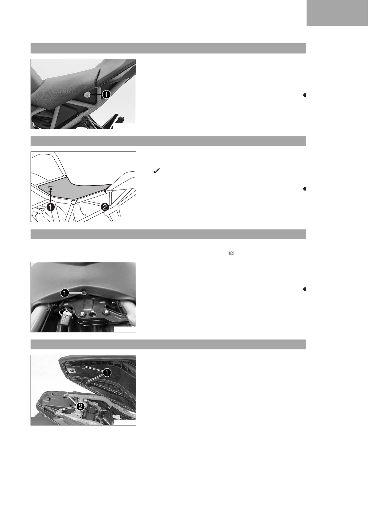
–Remove the front rider's seat. ( p. 5)
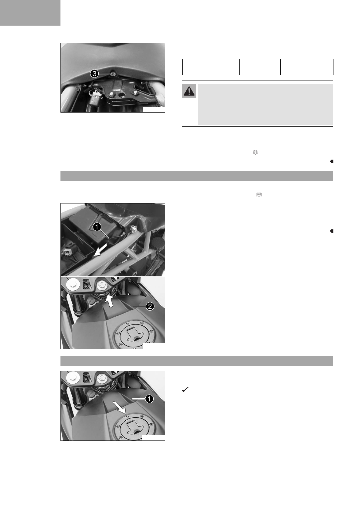
–Remove the battery cover. ( p. 6)
L02156-10
Main work
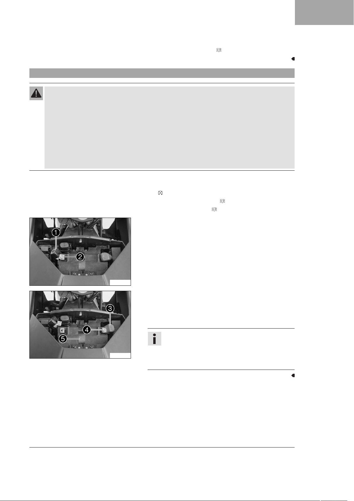
–Pull back the negative terminal cover 1.
–Disconnect the negative cable 2of the battery.
3.9 Recharging the battery
Warning
Risk of injury Battery acid and battery gases cause serious chemical burns.
–Keep batteries out of the reach of children.
–Wear suitable protective clothing and safety glasses.
–Avoid contact with battery acid and battery gases.
–Keep sparks or open flames away from the battery.
–Only charge batteries in well-ventilated rooms.
–Rinse the affected area immediately with plenty of water in the event of contact with the skin.
–Rinse eyes with water for at least 15 minutes and consult a doctor immediately if battery acid and
battery gases get into the eyes.
Warning
Environmental hazard Batteries contain environmentally-hazardous materials.
–Do not dispose of batteries as household waste.
–Dispose of batteries at a collection point for used batteries.
Warning
Environmental hazard Hazardous substances cause environmental damage.
–Dispose of oils, grease, filters, fuel, cleaning agents, brake fluid, etc., correctly and in compliance with
the applicable regulations.
Info
Even when there is no load on the battery, it discharges steadily.
The charging level and the method of charging are very important for the service life of the battery.
Rapid recharging with a high charging current shortens the service life of the battery.
If the charging current, charging voltage, and charging time are exceeded, the battery will be destroyed.
If the battery is depleted from starting the vehicle repeatedly, the battery must be charged immediately.
If the battery is left in a discharged state for an extended period, it will become over-discharged and sul-
fated, destroying the battery.
The battery is maintenance-free, i.e., the acid level does not have to be checked.
Preparatory work
–Remove the front rider's seat. ( p. 5)
–Remove the battery cover. ( p. 6)
–Disconnect the negative cable of the battery. ( p. 8)


 Supplementary service manual")