IMPORTANT SAFETY INSTRUCTIONS
SAVE THESE INSTRUCTIONS
READ ALL INSTRUCTIONS BEFORE USING THE FAN,
ESPECIALLY THESE BASIC PRECAUTIONS:
1. CAUTION: To reduce the risk of injury to persons, install fan
so that the blade is at least 3.05 meters (10 Feet) above the
floor.
2. WARNING: To reduce the risk of personal injury, do not bend
the mounting bracket when installing the bracket, balancing the
fan, or cleaning the fan.
3. The fan shall only be used for it’s intended purpose.
4. Do not immerse the fan in water or other liquids.
5. Turn off and unplug unit:
a) Before dismantling or assembling the fan; or
b) Before cleaning or servicing
6. Avoid touching mobile parts of the fan while in operation.
7. Avoid operation of the fan in the vicinity of flammable vapors, which
might cause an explosion.
8. Do not insert foreign objects into the openings on the front and rear
guards while the fan is in operation.
9. Do not use the fan if the power cord or plug has been damaged.
10. For safety reasons, do not use any accessories not
recommended or sold by the manufacturer.
11. Never operate the fan outdoors.
12. Do not allow the power cord to hang over sharp edges.
13. Do not allow any contact of the power cord with hot surfaces.
14. The fan is to be installed on a dry and even surface.
15. Do not operate the fan if the guards are not fitted or fastened
in place in accordance with the instructions.
WARNING: TO REDUCE THE RISK OF FIRE OR ELECTRIC
SHOCK, THIS FAN SHOULD ONLY BE USED WITH THE REMOTE
CONTROL SUPPLIED WITH THIS UNIT.
WARNING: TO REDUCE THE RISK OF FIRE, ELECTRIC SHOCK
OR PERSONAL INJURY, MOUNT THE FAN TO AN OUTLET BOX
MARKED ACCEPTABLE FOR FAN SUPPORT AND USE THE
MOUNTING SCREWS PROVIDED WITH THE OUTLET BOX.
ATTENTION: Installation of this fan must be in accordance with the
National Electrical Code, ANSI/NFPA 70-1993 and local codes.
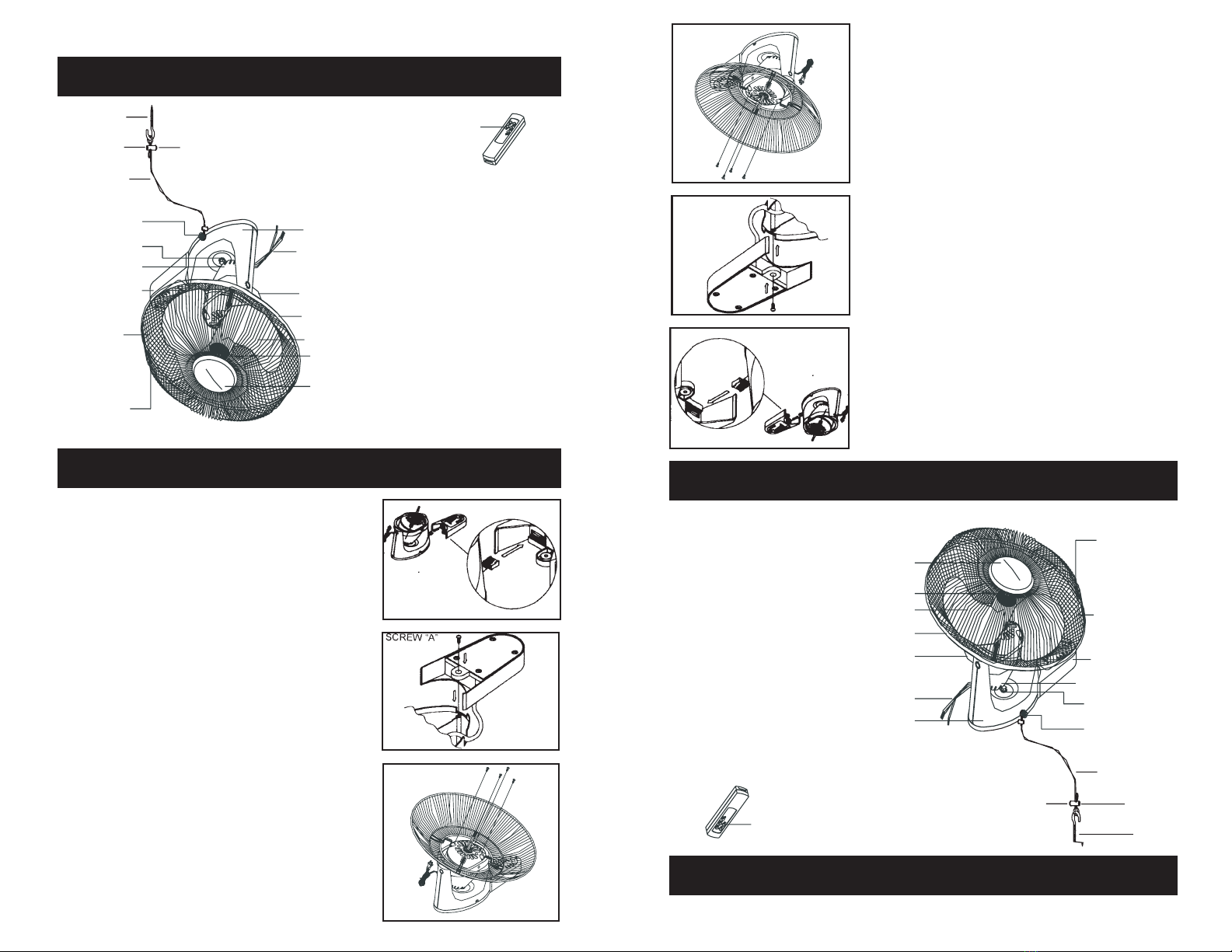
FAN & REMOTE CONTROL
PREPARATION
1) Remote Control: Open the battery compartment
and insert two AAA batteries.
2) Connect the power cord plug to a 120VAC power
outlet. You can now operate the fan by means of
remote control.
3) A change in the function is usually indicated by a beep.
All functions are controlled with the supplied remote. All
functions are enabled when the ON/OFF button is pushed
on the remote control. When power is off, the last operation
is memorized.
If possible, use leak-proof alkaline batteries.
INSTRUCCIONES DE SEGURIDAD IMPORTANTES
GUARDE ESTAS INSTRUCCIONES
LEA TODAS LAS INSTRUCCIONES ANTES DE UTILIZAR EL VENTILA-
DOR, ESPECIALMENTE LAS SIGUIENTES PRECAUCIONES BÁSICAS:
1. Precaución:Conelndereducirelriesgodelesiones,instaleelventi-
lador de manera que las aspas queden por lo menos 3.05 metros (10
pies) por encima del suelo.
2. Advertencia:Coneln dereducir elriesgo delesiones, nodoble el
brazodesoportealmomentodeinstalarlooalmomentodeequilibrar
elventiladoroefectuarlalimpieza.
3. Esteventiladorsólodebeutilizarseparalosnesquehasidodiseñado.
4. Nosumerjaelventiladorenaguauotroslíquidos.
5. Apague y desenchufe el electrodoméstico:
a)Antesdedesarmaroarmarelventiladoro,
b)Antesdeprocederconlalimpiezaoelmantenimiento.
6. Eviteelcontactoconlaspartesenmovimientodelventiladormientras
éste se encuentre funcionando,
7. Eviteponerafuncionarelventiladorcercaavaporesinamables,los
cualespodríanocasionarunaexplosión.
8. Noinserteobjetosextrañosdentrolasaberturasdelasrejillasdelan-
terayposteriormientraselventiladorseencuentrefuncionando.
9. Noutiliceelventiladorsielcordónoelenchufeseencuentrandañados.
10. Por razones de seguridad, no utilice accesorios no recomendados o
vendidosporpartedelfabricante.
11.Nuncautiliceelventiladorenexteriores.
12.Nopermitaqueelcordóncuelguesobrebordesalados.
13.Nopermitaqueelcordónentreencontactoconsuperciescalientes.
14.Instaleelventiladorsobreunasuperciesecayplana.
15.Noutiliceelventiladorsilasrejillasnoseencuentranbiencolocadas
o ajustadas en su lugar conforme a las instrucciones.
Advertencia:Conelndereducirelriesgodequeseproduzcaunincen-
dio o una descarga eléctrica, este ventilador debe utilizarse solamente
con el mando a distancia proporcionado con el equipo.
Advertencia:Conelndereducirelriesgodequeseproduzcaunincen-
dio,unadescargaeléctricaolesionespersonales,instaleelventiladoren
unacajadeelectricidadqueseaaceptableparasoportarelventiladory
utilice los tornillos de instalación incluidos dicha caja de electricidad.
Atención: La instalación de este ventilador debe efectuarse conforme
al Código Nacional de Electricidad, ANSI/NFPA 70-1993 y cualquier otro
código local.
3
3