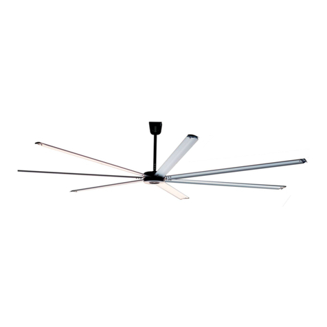
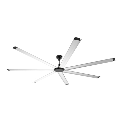
ANEMOI AIRPRO L User manual

AIRPRO [L]
Installation Manual
Issued March 2020
ANIM19AI Rev. A

AIRPRO [L]
2
UPDATES
DATE
UPDATE
DESCRIPTION
05/03/2020
A
First Edition
Technical documents are regularly updated. Anemoi reserves the right to modify the contents of this manual, in full or in part,
without warning.

AIRPRO [L]
3
TABLE OF CONTENTS
SAFETY..................................................................................................................................................................4
1INTRODUCTION............................................................................................................................................5
2TECHNICAL CHARACTERISTICS ...............................................................................................................6
3DIMENSIONS.................................................................................................................................................7
4DELIVERY .....................................................................................................................................................8
4.1 Package Dimensions & Weights............................................................................................................8
4.2 Packing List...........................................................................................................................................8
4.3 Fan diagram ........................................................................................................................................10
5MECHANICAL INSTALLATION..................................................................................................................11
5.1 Clearances ..........................................................................................................................................12
5.2 Installation Tools..................................................................................................................................13
5.3 I-Beam Conditions...............................................................................................................................13
5.4 Pre-installation Checklist .....................................................................................................................14
5.5 Blade guide..........................................................................................................................................14
5.6 Ceiling Mount Bracket..........................................................................................................................15
5.7 Safety Cable Installation......................................................................................................................16
5.8 Extension Tube Shield Installation.......................................................................................................17
5.9 Guy Wires Fixation (optional) ..............................................................................................................18
5.10 Blades Assembly.................................................................................................................................20
5.11 Drive Box Installation...........................................................................................................................21
6ELECTRICAL INSTALLATION ...................................................................................................................22
6.1 Power and Data Connections..............................................................................................................22
6.1.1 Multi Fans Installation......................................................................................................................25
6.1.2 Recommendations ..........................................................................................................................26
7MAINTENANCE...........................................................................................................................................27
8TROUBLESHOOTING.................................................................................................................................28

AIRPRO [L]
4
SAFETY
Thank you for purchasing our products!
Please read this manual carefully before use, use the product accordingly and keep the manual in safe place.
Installation work and electrical wiring must be done by qualified person(s) in accordance with all applicable codes
and standards.
Before the installation, read the following warning and caution instructions:
WARNING!
Do NOT install, repair or clean the fan while it is in operation or connected to the power supply. Failure
to do so may result in serious injury or death.
Do NOT install, handle, repair or clean the fan with wet hands. Failure to do so may result in serious injury
or death.
Do NOT use wires with worn or damaged insulation. Doing so may result in serious or fatal electrical shock,
fire or other accidents.
Ensure that the wires are held securely and protected from abrasion, chaffing, overload or other
damage. Risk of serious or fatal electrical shock, fire or other accidents.
Turn Off power to the fan if you detect any damage. Risk of serious or fatal electrical shock, fire or other
accidents.
Do NOT connect a damaged fan to the power supply. Risk of serious or fatal electrical shock, fire or other
accidents.
CAUTION!
Use proper lifting equipment to handle the motor and blade boxes. Otherwise, the fan could be damaged
and there is risk of accident.
Follow the instructions and recommendations contained in this manual carefully. Failure to do so may
result in incorrect installation.

AIRPRO [L]
5
1INTRODUCTION
The AIRPRO L series is the most powerful motor in the series and has been specially designed to be easily installed
in high ceilings. This fan combines IP55 to operate in the harshest ambient conditions and design. This fan is built-
in seven blades and the drives are provided in an external box to reduce maintenance and installation costs.
The main characteristics are:
•EC brushless motor without gearbox
•184mm ultra-thin motor
•Extremely silent fans
•7 aluminium blades
•Optional customized paint
•RS485 control
In addition, in combination with the traditional air conditioning systems, the use of fans allows generating important
energy savings of up 45% in winter and 25% in summer.

AIRPRO [L]
6
2TECHNICAL CHARACTERISTICS
AIRPRO 400 L
AIRPRO 500 L
AIRPRO 550 L
AIRPRO 600 L
AIRPRO 700 L
GENERAL CHARACTERISTICS
Diameter
4 m
5 m
5.5 m
6.1 m
7.3 m
Blades number
7 aluminium blades
Standard colour
Black matte colour and aluminium blades
MOTOR CHARACTERISTICS
Motor power
1,000W
1,000W
1,000W
1,000W
1,000W
Supply voltage
200VAC ~ 240VAC I, 50/60 Hz
Maximum consumption
825W
1,100W
585W
765W
1050W
Maximum consumption (A)
6.3 A
8.0 A
4.4 A
5.6 A
8.3 A
Maximum speed
115rpm
90rpm
65rpm
60rpm
50rpm
Protection degree
IP55
IP55
IP55
IP55
IP55
Sound level
<46dBA
<46dBA
<46dBA
<46dBA
<46dBA
Total weight
90kg
100kg
104kg
110kg
120kg
Operation temperature
-10ºC ~ 40ºC without derating
Motor type
Brushless EC motor
FAN PERFORMANCE
Airflow*
282,745 m3/h
381,705 m3/h
326,725 m3/h
398,740 m3/h
574,070 m3/h
Recommended coverage**
942 m²
1,272 m²
1,089 m²
1,329 m²
1,914 m²
Maximum coverage***
1319 m²
1,781 m²
1,525 m²
1,861 m²
2,679 m²
CONTROL
Controllers
Magnocontrol
OPTIONS
Extensions
Optional rod extensions of 1500 & 2000 mm
Colour
Optional paint or hydroprinting
Controller
Magnocontrol 10-25
REGULATION
Certifications
IECEE CB / BSMI
* Following AMCA 230-99 * Air Speed > 0.5 m/s ** Air Speed > 0.2 m/s

AIRPRO [L]
7
3DIMENSIONS
The Anemoi Airpro [L] has five different diameters. The height of the fan can also be varied by changing the length
of the extension rod. The next figure shows the fan dimensions with an extension drop of 643 mm:
Model
D
A
B
H1
H2
H3
AIRPRO 400 L
4.0 m
420 mm
250 mm
573 mm
1,000 mm
184 mm
AIRPRO 500 L
5.0 m
AIRPRO 550 L
5.5 m
AIRPRO 600 L
6.1 m
AIRPRO 700 L
7.3 m

AIRPRO [L]
8
4DELIVERY
The Anemoi Airpro [L] fan is delivered in two wood boxes, one including the motor parts and the other the blades.
Handle the fan boxes carefully and with proper lifting equipment to avoid any damage.
CAUTION!
Use proper lifting equipment to handle the motor and blade boxes. Otherwise, the fan could be damaged
and there is risk of accident.
4.1 Package Dimensions & Weights
The dimensions and weights of these boxes are listed in the following table:
Model
Box
WIDTH (mm)
DEPTH (mm)
HEIGHT (mm)
WEIGHT (kg)
AIRPRO [L]
Motor
1350
507
650
49
Blades
3526
305
225
32
4.2 Packing List
The following tables include the different pieces sent inside the boxes. Please check the status and quantity of the
fan equipment and the supporting parts immediately after you have opened the box to make sure that the goods
received are in accordance with your order. If parts are missing or damaged, please inform our company's
responsible person immediately for revision.
Blades box:
NO.
Component name
QTY
1
Fan Blade
7 pcs
Motor box:
NO.
Component name
QTY
1
Main Fan Unit, with:
- Motor
- Extension Rod
- Guy Wire Bracket (piece between motor
and extension rod)
- Mounting Bracket
- Mounting Base
- I-Beam Set Installation (2xI-Beam Clamp,
2xI-Beam Shim)
1 pc

AIRPRO [L]
9
2
Drive Box
1 pc
3
Extension Tube Shield
2 pc
4
Blade Guides
7 pc
Small Equipment box, included at motor box:
NO.
Component name
QTY
1
Safety Cable
1 pc
2
Wire Rope Clamp
20 pcs
3
End Caps
7 pcs
4
Turnbuckle
4 pcs
5
Beam clamp set
4 pcs
6
Earth Wire
1 pc
7
Blades Retainer
7 pcs
BOLTS
Connecting with
Screw standard
QTY
Blade Guides on motor
M10 Flat washer
14
M10 Spring washer
14
M10 Nut
14
Extension tube shield
M5*16 bolts
5
End-caps
M6*40 bolts
7
M6 Flat washer
14
M6 Spring washer
7
M6 Nut
7
Blades
M8*45 bolts
21
M8 Flat washer
42
M8 Spring washer
21
M8 Nut
21

AIRPRO [L]
10
4.3 Fan diagram
A - Safety Cable
B - I-Beam clamp
C - I-Beam shim
D - Mounting Base
E - Mounting bracket
F - Extension tube
G Extension tube shield
H - Extension tube clamp
I - Wire rope clamp
J - Blades Retainer
K - Main Fan Unit (motor)
L - Blade guides
M - Blades
N - End Caps

AIRPRO [L]
11
5MECHANICAL INSTALLATION
CAUTION!
Follow the instructions and recommendations contained in this section carefully. Failure to do so may
result in incorrect installation.
The Anemoi Airpro [L] fan is designed for ceiling installation. Ensure that the ceiling area chosen can hold the
weight of the fan and that there are no obstacles in its operating range. The maximum weight of the fan is about
120 kg and the maximum torque is about 42Nm.
Before installing the fan, it is necessary to sign and protect the working area to prevent anyone from going under
the fan. It is recommended to fence at least four meters around the lifting equipment.
Follow any national or local regulation regarding installations in height.
SAFETY!
Ensure that the ceiling area chosen can hold the weight and torque of the fan, and that there are no
obstacles in its operating range. Failure to do so may result in equipment damage or accident.
Ensure sign and protect the working area. Failure to do so may result in serious injury or death.
Ensure following any national or local regulation. Failure to do so may result in serious injury or death.
Do NOT install the fan while it is in operation or connected to the power supply. Doing so may result in
serious or fatal electrical shock.

AIRPRO [L]
12
5.1 Clearances
In order to ensure the maximum coverage of the Anemoi Airpro [L], all obstacles that may be encountered within
the radius of the fan and between the horizontal height of the fan's static position and the ceiling should be
considered before installation, ensuring that the fan has an appropriate clearance in all directions when running.
If there are lamps above the fan blades, change their position if necessary, to avoid the strobe effect. Ensure that
the fan is installed at a height greater than 3,05 meters.
The next figures show all clearances:
If the fan is installed in an inclined roof, ensure that these minimum distances are achieved and add a higher
extension rod if necessary, to allow the fan take enough air and provide the maximum performance. It is
recommended to protect the fan if there is the possibility to receive impacts.
CAUTION!
Ensure that the minimum distances are achieved. Otherwise, the fan could be damaged.
Protect the fan if there is the possibility to receive impacts. Otherwise, the fan could be damaged.

AIRPRO [L]
13
5.2 Installation Tools
To install the fan, ensure having the following required tools:
NO.
Name
Quantity
1
Standard wrench set
1
2
Standard socket set with ratchet
1
3
Standard Allen wrench set
1
4
Phillips screwdriver
1
5
Hydraulic cutter
1
6
Torque wrench (5-45 Nm)
1
7
Flat head screwdriver
1
8
Multimeter
1
9
Pair of #14 to #24 AWG strippers
1
10
Electronic level
1
5.3 I-Beam Conditions
In case of I-Beam installation, make sure the minimums requirements are met:
Please consult with structural engineer to make sure your building is approved for fan installation.
Minimums requirements for I-Beam are shown below:
1. Width (B) of 135-375 mm
2-1. Thickness (t) of 14-20 mm, the
Mounting Base need 2 I-Beam shims.
2-2. Thickness (t) of 14 mm, the
Mounting Base need 1 I-Beam shim.
SAFETY!
Ensure the minimum requirements are met. Failure to do so may result in serious personal injury or death
and equipment damage.

AIRPRO [L]
14
5.4 Pre-installation Checklist
Before installation, make sure the following requirements are met:
Check
Description
The fan can only be mounted to the I-beam or a concrete beam. DO NOT mount the fan directly to
a single stringer, truss shelf or light steel shelf. For installation methods not included in this manual,
please consult a structural engineer.
The mounting structure approved by structural engineers. The mounting system must be able to
withstand the torque generated by the fan.
Having been familiar with the functions of the safety cable.。.
For the fan installation, the fan blades should be at least 3,05 meters above the ground. Please
refer to section 5.1 Clearances.
For the fan installation, the distance between the blades and other objects/building structure should
be at least 0,6 meters. Please refer to section 5.1 Clearances.
The center-to-center distance between two fans should be at least 3 times the diameter of the fans.
The Mounting Base kit size should match the I-beam. Please refer to section 5.3 I-Beam conditions.
SAFETY!
Ensure the minimum requirements are met. Failure to do so may result in equipment damage.
5.5 Blade guide
The Anemoi Airpro [L] comes with seven blade guides for install the blades easily
1. Install the 7 blade guides on the
motor, this step can be completed on
the ground. (Recommended
tightening torque: 24Nm)
Use M10 Bolt Kit (14 x M10)

AIRPRO [L]
15
5.6 Ceiling Mount Bracket
The Anemoi Airpro [L] comes with mounting brackets (Mounting Base) to anchor the fan to the ceiling. As standard,
all tooling is provided so that the fan can be mounted in I beams or concrete beams. The fan is prepared to be
installed in inclined roofs.
2. Secure the Mounting Base to I-
beam or directly to concrete ceiling.
(Recommended tightening torque: 42
Nm)
Use Mounting Base Bolt Kit (4 x
M12*60)
3-1. Slide the motor, main fan unit to
the Mounting Base, hanger the
Mounting Bracket and securely
fasten.
3-2. Ensure the nuts on the hanger is
tightened. (Recommended tightening
torque: 42Nm)
Use Mounting Bracket Bolt Kit (4 x
M12*45)
CAUTION!
Do not lift the motor weight alone. Failure to do so may result in serious injury or equipment damage.
Ensure that the M12 Mounting Bracket bolts are correctly fastened. Failure to do so may result in equipment
damage.
Ensure that the motor is in vertical position once is assembled. Failure to do so may result in equipment
damage.

AIRPRO [L]
16
5.7 Safety Cable Installation
The motor box contains a safety cable that must be installed to prevent the engine from failing after assembly. To
do so, please use four Wire Rope Clamp and the Safety Cable. If the fan is mounted on a steel or concrete beam,
wrap the beam with the safety cable in a closed loop as shown below:
4-1. Route safety cable wrap it around
the I-beam and thought the Mounting
Base, securely lock the wire rope
clamp.
4-2. The safety cable must be
tightened as picture shows, make
sure the U-shaped inside the wire
rope clamp is tighten to the short side.
(Recommended Tightening Torque:
12Nm)
Use 4 x Wire Rope Clamp and 1 x
Safety Cable.
If the fan is anchored to a concrete ceiling, please drill the ceiling to install a pin that can support the weight of the
fan at a distance of 20-
cable in a closed loop.
SAFETY!
Ensure that the safety cable is correctly installed to prevent the fan from falling. Failure to do so may
result in serious personal injury or death and equipment damage.
Make sure the Wire Rope Clamp are properly tightened. Failure to do so may result in equipment damage.

AIRPRO [L]
17
5.8 Extension Tube Shield Installation
The extension tube shield is provided in order to protect the safety cable and wiring. To do so, please use four
bolts of the Extension tube shield bolt kit that is provided in the motor box, as shown below:
5-1 Connect three-phase terminals
(U, V, W) to drive box.
5-2 Connect the earth wire with
extension tube..
Use Extension Tube Shield Bolt Kit
(1 x M6*16) and 1 x Earth Wire
5-3 Fix the extension tube shied with
bolts after fasten all the safety cables
and wires. Recommended tightening
torque: 5Nm.
Be careful by installing, so do not
damage the wiring.
Use Extension Tube Shield Bolt Kit
(4 x M6*16)
SAFETY!
Connect the Earth Wire with the extension tube. Failure to do so may result in equipment damage.
Ensure that all the safety cables and wires are properly tightened. Failure to do so may result in equipment
damage.
Make sure do not damage the wiring while the Extension Tube Shield is being installed. Failure to do so
may result in equipment damage.

AIRPRO [L]
18
5.9 Guy Wires Fixation (optional)
If oscillations are detected, winds must be installed as part of the assembly process. The use of winds is
recommended for extensions greater than the standard extension.do so, there is an auxiliary hardware with
Turnbuckle, Wire Rope Clamp and Beam Clamp set. Please introduce the guy wires in the Guy wire bracket fixed
in the motor in a 45º angle as shown below:
6-1. Prepare 4 wires with Ø6mm
when installation, these cables are
not provided.
6-2. Looking up from the bottom of
ceiling fan, the angle between each
cables and I-beams is recommended
to be 45-degrees.
6-3 The angle of the cables should be
and 45 degrees angle from horizontal
surface.
7-1. Prepare and secure the beam
clamp tightly, you can finish this
process ahead on the ground to
speed up the efficiency.
11-2. The technician needs toprepare
the guy wire and tailor it according to
the situation. Recommended
Tightening Torque: 12Nm
Use 4 x Beam Clamps Set and 8 x
Wire Rope Clamp.
8-1 Attach the beam clamps to the I-
beam and securely fasten to the
proper position based on step 6.
8-2 Pass the safety cable through the
ring and secure with guy wire bracket.
Recommended Tightening Torque:
24Nm

AIRPRO [L]
19
9-1. Based on step 9, tighten the guy
wire with turnbuckle and wire rope
clamp as picture shows.
9-2 Adjust the turnbuckle to balance
the ceiling fan.
Recommended Tightening Torque:
12Nm.
Use 8 x Wire Rope Clamp and
4 x Turnbuckle.
CAUTION!
Fasten the guy wires clamps correctly to ensure that they cannot be unscrewed. Failure to do so may
result in equipment damage.

AIRPRO [L]
20
5.10 Blades Assembly
To assemble the blades, it is necessary to screw the plastic end caps, and introduce and fix them to the motor
guides. Use the M6 bolts to fix the plastic end caps before lifting the blade to the motor.
10. Insert the end-cap into the blade
and tighten with the 7 bolt kits as
picture shown.
Please. Process this step on the
ground.
Recommended Tightening Torque:
5Nm.
Use End-Caps Bolt Kit (7 x M6*45).
Once the end caps are screwed, remove the plastic protection film and proceed to lift the blade to the motor. Take
care to avoid any damage on the blades paint. The fan blades must be installed in a specific sense, with the
concave side in the bottom.
11-1. Insert the blade into the blade
guide and tighten it. Recommended
tightening torque: 12Nm
11-2. Place retainer over the blade
and spans to the other blade.
Use Blades Bolt Kit (21 x M8*45).
CAUTION!
Make sure the blades are installed in the correct sense. Failure to do so may result in incorrect installation.
Tighten the outside bolts first and then the inside bolts with the blades’ retainer. Failure to do so may
result in incorrect installation.
Check that there are no objects that can avoid the blades rotation. Failure to do so may result in equipment
damage.
Retainer
This manual suits for next models
5
Table of contents
Other ANEMOI Fan manuals
Popular Fan manuals by other brands

Polaris
Polaris PSF 40 RC Manual instruction

Helios
Helios SlimVent Series Installation and operating instructions

Dynex
Dynex DX-FANT12-A Guide d'installation rapide

Progress Lighting
Progress Lighting AirPro P2578 Installation guides

Dantherm
Dantherm DanX 1 user manual

Airflow
Airflow 7006A installation instructions