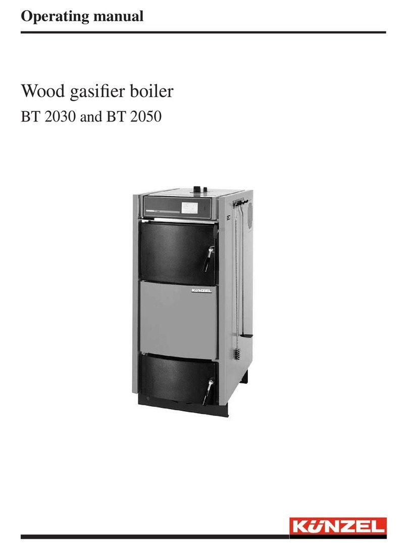
The type identification plate is located behind the ash hatch. Immediately below it is a welded plate with
the boiler number.
3.2 Chimney connection
The exhaust gas duct to the chimney should be as short as possible, without any bends and installed at a
slight incline. The connection to the chimney should have anaerodynamic design that curves upward. The
connector joining the furnace and the chimney must comply with EN 1856-2:2004 and have the required
identification marking (CE). In accordance with EN 1856-2:2004 non-insulated connectors must be kept
at least 40 cm away from combustible components. We recommend the use of insulated connectors.
The figures required for the chimney design calculations can be found in the technical data listed in
section 11 on page 30. Calculated chimney diameters that are smaller than the flue gas branch of the
boiler are not permissible.
Please note: Please note that the low exhaust temperatures occurring during prolonged operation may
mean that it is necessary to fit a moisture-resistant chimney (thermal conductivity factor - resistance
group I in accordance with DIN 18160/T1).
Before connecting the pellet boiler to an existing chimney, subject it to a chimney calculation or obtain
a chimney report. Before commencing with the installation it is essential to obtain the approval of your
local master chimney sweep.
An insufficient draft or a dirty flue gas system will be detected by the burner via the temperature
sensors. The display unit of the burner control unit will then display the fault message „flue draft
insufficient“. Should this occur, the control lamp will switch to yellow and thereby show that the burner
is in emergency operation mode. The display unit will then alternately show the above fault message
and the fault message „reduced output“. If the problem cannot be handled by reducing the output of the
burner and dangerous temperatures occur at the sensors, the burner will be switched off once the upper
temperature limit is reached.
3.3 Description of operation and design
The pellets are transferred by a screw conveyor from an external storage unit to the filling spout of the
burner. They are then transferred by a dosage screw auger into the discharge chute, after which they fall
into the brazier. The drop distance serves as burnback protection.
The level of pellets in the filling spout is monitored. The LED of the chamber full sensor goes out if the
level of the pellets in the connection has fallen below the measurement range of the chamber full sensor.
In normal operation, the external conveyor screw starts to run two minutes after the LED goes out and
then remains active until the LED lights up once again and the filling spout is filled with pellets. The
control unit is to be set so that the motor of the external conveyor screw runs for a maximum of two
minutes. If the filling spout of the burner is not filled with pellets in this time, the display lamp switches
from green to red and the text „external !!! MALFUNCTION !!!“ appears in the display unit. (see also
„Control panel - description of operation“ ).
According to the filling system employed, it can therefore be necessary to adjust the parameter 41 in
the service menu of the burner control unit. For more information on this subject please refer to section
4.3.3 on page 14.
7


