manuals.online logo
Brands
  1. Home
  2. •
  3. Brands
  4. •
  5. Vaillant
  6. •
  7. Boiler
  8. •
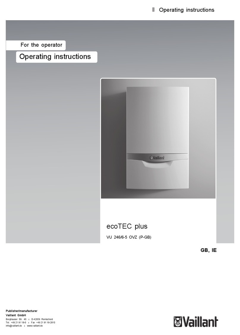
  9. Vaillant aquaPLUS VUI 362-7 User manual

Vaillant aquaPLUS VUI 362-7 User manual

VUI 362-7
For the user
GB
Instructions for use
aquaPLUS
Gas fired room sealed fan assisted
combination boiler with 15L store
834641_12GB_032005.qxd 09.03.2005 16:42 Uhr Seite 1
2
page
Information to the documentation . . . . . . . . . . . . 2
Attachment and safe storage of the documentation 2
ey to symbols . . . . . . . . . . . . . . . . . . . . . . . . . . . . . . . 2
1 General information . . . . . . . . . . . . . . . . . . . . . . 3
1.1 For your information . . . . . . . . . . . . . . . . . . . . . 3
1.2 Liability . . . . . . . . . . . . . . . . . . . . . . . . . . . . . . . . 3
1.3 Specified use . . . . . . . . . . . . . . . . . . . . . . . . . . . 3
1.4 EC designation . . . . . . . . . . . . . . . . . . . . . . . . . 3
1.5 Factory Guarantee . . . . . . . . . . . . . . . . . . . . . . . 3
2 Safety . . . . . . . . . . . . . . . . . . . . . . . . . . . . . . . . 4
2.1 Safety instructions . . . . . . . . . . . . . . . . . . . . . . 4
2.1.1 Setup and adjustments . . . . . . . . . . . . . . . . . . 4
2.1.2 Gas smell . . . . . . . . . . . . . . . . . . . . . . . . . . . . . . 4
2.1.3 Modifications in and around the boiler . . . . . . 4
2.1.4 Explosive and flammable materials . . . . . . . . . 4
2.1.5 Inspection . . . . . . . . . . . . . . . . . . . . . . . . . . . . . . 4
2.2 General precautions . . . . . . . . . . . . . . . . . . . . . 4
2.2.1 Corrosion protection . . . . . . . . . . . . . . . . . . . . . 4
2.2.2 Drinking water supply pressure . . . . . . . . . . . . 4
3 Operation . . . . . . . . . . . . . . . . . . . . . . . . . . . . . . 5
3.1 Overwiev . . . . . . . . . . . . . . . . . . . . . . . . . . . . . . . 5
3.1.1 Operating controls . . . . . . . . . . . . . . . . . . . . . . . 5
3.1.2 Boiler display . . . . . . . . . . . . . . . . . . . . . . . . . . . 5
3.2 Initial checks before turning ON . . . . . . . . . . . 6
3.2.1 Open the service valves . . . . . . . . . . . . . . . . . . 6
3.2.2 Check the water contents . . . . . . . . . . . . . . . . . 6
3.3 Domestic hot water operation . . . . . . . . . . . . . 6
3.3.1 Warmstart operation . . . . . . . . . . . . . . . . . . . . 7
3.3.2 Obtaining hot water . . . . . . . . . . . . . . . . . . . . . . 7
3.4 Heating operation . . . . . . . . . . . . . . . . . . . . . . . 8
3.4.1 Setting the maximum radiator
temperature control . . . . . . . . . . . . . . . . . . . . . 8
3.4.2 Setting the external controls . . . . . . . . . . . . . . 8
3.5 Status display . . . . . . . . . . . . . . . . . . . . . . . . . . . 9
3.6 Resetting the appliance . . . . . . . . . . . . . . . . . . . 9
3.6.1 Faults in the hot water system . . . . . . . . . . . . . 10
3.7 Turning the boiler OFF . . . . . . . . . . . . . . . . . . . 10
3.7.1 To turn OFF the central heating only
(Summer mode) . . . . . . . . . . . . . . . . . . . . . . . . . 10
3.7.2 To turn OFF central heating and hot water
for short periods of time . . . . . . . . . . . . . . . . . . 11
3.8 Care and maintenance . . . . . . . . . . . . . . . . . . . 11
3.9 Frost protection . . . . . . . . . . . . . . . . . . . . . . . . . 11
3.10 Troubleshooting . . . . . . . . . . . . . . . . . . . . . . . . . 11
Table of contents Information to the documentation
Instructions for use VUI 362-7
Important note!
This is possibly a dan erous situation for the
product and the environment!
Note!
Useful information and uidelines.
• This symbol is used to indicate a required step.
834641_12GB_032005.qxd 09.03.2005 16:42 Uhr Seite 2
3
General information 1
3Instructions for use VUI 362-7
1 General information
1.1 For your information
Thank you for choosing a Vaillant boiler. The information
given in this booklet will enable you to obtain the best
performance from your boiler.
aquaPLUS provides both central heating and domestic
hot water, with the domestic hot water supplied directly
from the boiler. The boiler will operate automatically to
provide domestic hot water whenever a hot water tap is
opened, and automatically adjusts to meet the demand
for both central heating and domestic hot water in the
most economical way.
If, after reading these instructions, you have any
questions on the operation of the boiler, please contact
either your installer or Vaillant Technical Department.
1.2 Liability
Warnin !
We can accept no liability whatsoever for
dama e or injury resultin from failure to
observe these instructions.
1.3 Specified use
Vaillant aquaPLUS boilers are made to fulfil the latest
technical specifications and official safety regulations.
These appliances are designed as boilers for use in
central heating and hot water supply systems.
If the appliances are used for purposes other than or in
excess of these specifications, this shall be
classed as incorrect operation, and neither the
manufacturer nor supplier will accept any liability for
resulting damage or injury.
Use of this type is entirely at the owner’s risk.
The term "specified use" also covers observance of the
operating and installation instructions, along with
adherence to the servicing schedules.
The benchmark gas boiler commissioning checklist (in
the installation manual) should be completed by the
installer and/or the commissioning engineer.
All CORGI Registered Installers carry a CORGI ID card,
and have a registration number. Both should be
recorded in the Benchmark gas boiler commissioning
checklist.
You can check your installer by calling CORGI direct on
01256 372300.01256 372300.
1.4 EC desi nation
The purpose of EC designation is to certify that the
boiler complies with the requirements of the directives
covering gasfired appliances (Council directive
90/396/EEC) and electromagnetic compatibility (Council
directive 89/336/EEC).
These appliances also comply with the requirements of
the directive on operating efficiency (Council directive
92/42/EEC).
1.5 Factory Guarantee
Our confidence in the quality of craftmenship and
performance of our products is demonstrated by the
Vaillant two year guarantee.
During the first year from installation the guarantee
covers your boiler against manufacturing defects for
both parts and labour. In order to extend this guarantee
to the second year from installation all you have to do is
ensure that your boiler receives a service when it is a
year old. (Please note that the cost of the service is not
included in the guarantee).
Important
To qualify for the your two year uarantee:
The boiler must be serviced either by Vaillant Ltd. or
another competent servicing company (CORGI
registered) within one year of the installation date and
the details recorded in the Benchmark gas boiler
commissioning checklist (this should have been
completed by the installer).
Please note that the cost of the service is not included
in the guarantee.
Re isterin with us
Registaration is simple. Just complete the Guarantee
Registration Card and return to Vaillant within 30 days
of installation. Your details will then be automatically
registered within the Vaillant scheme.
Note: No receipt will be issued.
Immediate help
If your Vaillant boiler develops a fault your first action
should be to contact your installer, as his professional
assessment is needed under the terms of our
Guarantee. If you are unable to contact your installer,
phone Vaillant Service Solutions: 0870 6060 777.
834641_12GB_032005.qxd 09.03.2005 16:42 Uhr Seite 3
4
2 Safety
Instructions for use VUI 362-74
Attention!
The device may only be used
• for initial operation
• for testin
• for continuous operation
with the chamber cover closed and with the flue
system fully mounted and sealed.
2.2 General precautions
2.2.1 Corrosion protection
DO NOT use aerosol sprays, solvents, chlorine-based
cleaning products, paints, adhesives, etc. in the vicinity
of the unit. The use of these items can, under certain
circumstances, also result in corrosion damage to the
flue outlet system.
2 Safety
2.1 Safety instructions
2.1.1 Setup and adjustments
Installation and adjustment of the boiler as well as
service maintenance and repair of the boiler may only
be carried out by a competent person in accordance
with the Gas Safety (Installation and Use) Regulations
1998. (In the U. . "CORGI" Registered installers
undertake the work to a safe and satisfactory standard).
If the boiler is installed in a compartment do not
obstruct any purpose provided ventilation openings, and
do not use the compartment for storage purposes.
2.1.2 Gas smell
If you smell gas or suspect a gas leak:
• Turn off the boiler
• Do not switch the light or any electrical switches in
the hazardous area on or off, do not use the telephone
in the hazardous area, avoid sparking, such as lighting
the lighter or matches
• Do not smoke in the hazardous area
• Turn off the gas supply at the gas meter
• Ventilate the room
• Warn the other occupants and leave the house
• Consult your gas supplier, service agent or other
competent person.
2.1.3 Modifications in and around the boiler
No modifications may be made to the following items:
• The boiler
• The gas, water and electrical supply
• The flue system
• The safety valve for the heating water
• Any structural changes around the appliance that
could affect the operational safety of the boiler.
2.1.4 Explosive and flammable materials
Do not use or store any explosive or highly flammable
materials (e.g. gasoline, paper or paint) near to the
appliance.
2.1.5 Inspection
The boiler should be serviced annually. We recommend
that you sign a service agreement with your service
agent or Vaillant Ltd.
Important!
When ti htenin or slackenin screwed connec-
tions always use suitable open-ended spanners
(not pipe wrench, or extensions, etc.).
Incorrect use and/or unsuitable tools can lead to
dama e bein caused (e. . as or water leaka e)!
834641_12GB_032005.qxd 09.03.2005 16:42 Uhr Seite 4
5
peration 3
Instructions for use VUI 362-7 5
3.1.2 Boiler display
aquaPLUS boilers have an advanced multifunction boiler
display. When the main ON/OFF control is in the "ON"
position the display will normally show the temperature
of water in the boiler circuit (50° C in the example),
which confirms that the boiler is functioning correctly.
The display supplies the following information:
1 Fan speed malfunction
2 Heating demand
3 Hot-water demand
4 Warm-start on (Comfort mode)
5 Pump on
6 Gas valve on
7 Actual Heating-system flow temperature (e.g. 50 °C)
or
Displaying of a status/error code
8 Correct burner operation (normal flame) or
lock out (crossed-out flame)
Fi . 3.2: Display indications
0
I
C
o
C
o
VRC-VC
123
7
654
8
3 Operation
3.1 Overwiev
3.1.1 Operatin controls
For access to the controls pull the side edges of the
lower front panel and drop it down.
The following can be seen:
1 Maximum radiator temperature control
2 The "+" and "-" buttons for the display panel
3 Main ON/OFF control
4 Pressure gauge displaying the pressure in the heating
system
5 Built in control/timer module (if fitted)
6 The "i" information button
7 Boiler display
8 "Reset" button
9 Maximum hot water temperature control and
warmstart ON/OFF control
Fi . 3.1: Operatin elements
0
I
C
o
C
o
32 4
85
1
9
VRC-VC
76
834641_12GB_032005.qxd 09.03.2005 16:42 Uhr Seite 5
6
3 peration
Instructions for use VUI 362-76
Fi . 3.4: Checkin the water level
3.3 Domestic hot water operation
Warnin !
The boiler should only be used when the heatin
system contains water. Use of the boiler without
water may cause dama e to the boiler or its
components.
Settin the maximum domestic hot water
temperature control
• Turn the main switch (2, Fig. 3.5) to the "l" position.
• The domestic hot water temperature can be adjusted
using the hot water temperature control (3, Fig. 3.5).
• Turn the control clockwise to increase the
temperature and anti-clockwise to decrease the
temperature.
As a guide for normal circumstances set the knob to the
one o´clock position.
Note!
This control adjusts the maximum domestic hot
water temperature. If adjustin the control
upwards appears to have no effect on the
temperature, then the boiler is already operatin
at full output for the selected flow rate.
Warnin !
If you live in a hard water area please do not set
the control knob above the mid (12 o'clock)
position to prevent excessive scale formation
(fi . 3.5).
VRC-VC
C
o
0
I
C
o
1
3.2 Initial checks before turnin ON
3.2.1 Open the service valves
• Ensure the cold water service valve is open. This can
be checked by opening a hot water tap and ensuring
water flows.
• Ensure that the service valves in the heating flow and
return (2 and 1) and the gas service valve (3) are open.
Note!
The flow, return and as service valves are open
when the line markin has the same direction as
the pipe.
• The pressure relief valves (4) are provided for safety
reasons and must not be interfered with.
Note!
A bottom cover is fitted to the appliance. The
service valves can be seen throu h the cover.
Fi . 3.3: Openin service valves
3.2.2 Check the water contents
• Check the water contents of the system on the
pressure gauge (1).
The needle on the pressure gauge (1) should be within
the green band (between 1 and 1.5 bar). If the needle
displays a value below 0.75 bar when the appliance is
cold, follow the instructions left by your installer to refill
the system. Alternatively, your installer should be called
to refill the system.
I
0
2 3 1 4
834641_12GB_032005.qxd 09.03.2005 16:42 Uhr Seite 6
7
peration 3
Instructions for use VUI 362-7 7
Fi . 3.5: Domestic hot water supply
3.3.1 Warmstart operation
The warmstart facility provides instantaneous delivery
of domestic hot water from the aquaPLUS boiler.
When the warmstart system is switched ON the boiler
will automatically light periodically to maintain the
internal temperature of the boiler. When the warmstart
system is switched OFF a short delay may be
experienced in obtaining hot water at the tap.
• The warmstart system is activated by turning the hot
water temperature control knob (1) all the way to the
very right for a short time. Reset the hot water
temperature control knob to the desired setting. The
symbol "C" (comfort) appears in the display and
shows that the Warmstart system is activated. The
boiler will now provide instantaneous delivery of hot
water directly when a hot water tap is turned on.
• The Warmstart system is switched off by momentarily
turning the knob (1) to the left, as far as the stop. The
"C" symbol no longer appears in the display. Reset the
hot water temperature control knob to the desired
setting.
Note!
Irrespective of whether the warmstart facility is
switched on or off, the boiler will automatically
operate to provide hot water whenever a hot
water tap is opened.
C
o
0
I
C
o
VRC-VC
C
o
C
o
2
3
Fi . 3.6: Switchin the warm start on and off
3.3.2 Obtainin hot water
When you open a hot water tap (1) at a draw-off point
(wash basin, shower, bath etc.), the appliance supplies
you with the hot water you require.
When a certain volume of water has been drawn off, the
appliance is brought into operation automatically and
the integrated hot water storage vessel is re-filled (in
some circumstances, the appliance may operate only
after the water has been drawn off).
Warnin !
The appliance is equipped with an automatic
protection function a ainst le ionella: If the
temperature in the hot water stora e vessel falls
below 50 °C, then the vessel will be heated to
65 °C once in a 24 hr period. In this way, the
water in the stora e vessel is thermally
disinfected. Please note that after completion of
the thermal disinfection process there is a
possible risk of scaldin when drawin off hot
water.
Fi . 3.7: Drawin off hot water
1
C
o
C
o
1
1a
b
a
b
834641_12GB_032005.qxd 09.03.2005 16:42 Uhr Seite 7
8
3 peration
Instructions for use VUI 362-78
3.4.2 Settin the external controls
• Set the room thermostat (3, accessory) and/or the
thermostatic radiator valves (4, accessory) according
to the instructions supplied with the control(s).
Note!
Vaillant offer room thermostat/ time control
accessories which ive accurate and economic
room temperature control as well as improved
comfort.
Ask your installer!
The boiler will now operate automatically to provide
central heating for the conditions selected on the
external controls and also provide domestic hot water
on demand).
Whilst the boiler is operating, the boiler display (7, fig.
3.2) indicates the temperature of the water within the
boiler circuit. After the boiler stops operating the pump
and fan will continue to operate for a short period to
fully disperse the heat from the boiler.
Note!
The boiler incorporates an anti-cyclin
economiser control to prevent ener y wasteful
ON and OFF operation of the boiler for short
periods when in the central heatin mode. When
turnin the room thermostat to a hi her settin
there may therefore be a short delay before the
boiler operates.
Fi . 3.9: Settin the external controller
34
3.4 Heatin operation
3.4.1 Settin the maximum radiator temperature
control
• Turn the main switch (1) to the "l" position.
• Set the maximum radiator temperature control to the
desired setting using the control knob (2). We
recommend the following settings:
- Left setting during spring and autumn (turning the
control knob all the way to the very left switches OFF
heating),
- Middle setting during mild winter,
- Right setting during cold winter.
Fi . 3.8: Settin the flow temperature
VRC-VC
C
o
0
I
C
o1
2
C
o
C
o
C
o
834641_12GB_032005.qxd 09.03.2005 16:42 Uhr Seite 8
3.5 Status display
(For maintenance and service work performed by your
installer or service agent)
The status displays are activated by pressing the "i"
button (1). The current status code, e.g. "S.34" for the
frost protection mode, is shown on the display (2).
Pressing the "i" button again will switch you back to the
normal mode.
The "+" and "-" buttons will only be used by your
installer or service agent during service and
maintenance work.
Fi . 3.10: Status displays
Table 3.1: Status displays (A complete overview of the status
codes can be found in the installation instructions).
* Heating operation, ** Hot water operation
2
1
VRC-VC
C
o
0
I
C
o
9
peration 3
Instructions for use VUI 362-7 9
3.6 Resettin the appliance
When a hot water tap or the central heating system
requires heat, the boiler automatically ignites and starts
to operate. If the automatic ignition is not successful
within 10 seconds, then the boiler does not go into
operation and switches to "Lock out".
This is indicated visually by the crossed out flame in the
display and the displaying of fault code "F.28" or "F.29"
(flame extinguished during operation). A new attempt to
ignite the flame can then only be performed after
pressing the "Reset" button.
• Press the "Reset" button (2) and hold for approx. 1
second.
Warnin !
If the boiler still shuts off after a third attempt,
then please consult your installer or Vaillant
Service Solutions.
The boiler also switches to "Fault" when there is not
enough water in the system. This fault is indicated by
fault codes "F 22", "F.23" or "F.24". The boiler must only
be placed back in operation after the heating system has
been properly refilled with water.
In the unlikely event of any other fault developing, which
prevents the boiler from operating, the display will also
show other fault codes. If a fault code is displayed
please contact your installer or Vaillant Service
Solutions.
Note!
If contactin Vaillant Service Solutions please
remember to quote the fault code, as this will
help to pinpoint the fault.
Fi . 3.11: Reset
C
o
0
I
C
o
VRC-VC
Display Meanin
S.00* No heating demand
S.02* Pump running
S.03* Ignition sequence
S.04* Burner ignited
S.05* Fan and water pump over run
S.07* Water pump over run
S.08* Anti cycling mode (after heating operation)
S.10** Hot water demand
S.20** Tank cycle mode active
S.28** Anti cycling mode (after tank filling)
S.34* Frost protection mode active
834641_12GB_032005.qxd 09.03.2005 16:42 Uhr Seite 9
10
3 peration
Instructions for use VUI 362-710
3.7 Turnin the boiler OFF
3.7.1 To turn OFF the central heatin only (Summer
smode)
• Turn the maximum radiator temperature control knob
used to control the heating supply temperature (1) all
the way to the left.
Note!
You can switch off the heatin operation in
summer, for example, but the boiler will continue
to provide domestic hot water whenever a hot
water tap is opened.
Fi . 3.13: Settin the summer operatin mode
VRC-VC
C
o
0
I
C
o
C
o
C
o
C
o1
Fi . 3.12: Reset
3.6.1 Faults in the hot water system
To protect the storage vessel feed pump, the appliance
is equipped with dry-running protection. This prevents
operation of the feed pump if an insufficient quantity of
water is available in the appliance. If dry-running
protection is activated, reset the appliance as follows:
• Press the "Clear fault" button (see 2, illustration 3.12)
and hold it down for approx. 1 sec. or, alternatively,
switch the appliance main switch "OFF" and "ON"
again.
If the boiler still shuts off after a third attempt, please
consult your installer or Vaillant Service Solutions.
C
o
0
I
C
o
VRC-VC
2
STOP
max. 3 x
834641_12GB_032005.qxd 09.03.2005 16:42 Uhr Seite 10
11
peration 3
Instructions for use VUI 362-7 11
3.7.2 To turn OFF central heatin and hot water for
short periods of time
• Turn the main ON/OFF control (2) to the "0" position.
Note!
If you want to turn the aquaPLUS boiler OFF for
a lon er period of time (e. . holidays), and there
is no dan er of frost, then you should also turn
off the as supply, the cold water service valve
and the electrical supply. Please note the frost
protection hints in this re ard.
Fi . 3.14: Shuttin down the unit completely
3.8 Care and maintenance
Clean the outer casing of your boiler with a damp cloth
and a little soap. Do not use abrasive or solvent
cleaning agents that may damage the case or the plastic
fittings.
The appliance should be serviced at least once per year.
To ensure regular servicing, it is strongly recommended
that arrangements are made with your service agent or
Vaillant Ltd. For further details please contact Vaillant
Service Solutions: (0870 6060777).
3.9 Frost protection
Your boiler is equipped with a frost protection function:
If the heating water temperature drops below 5 °C when
the main switch is ON, then the boiler goes into
operation and heats the boiler circuit to approx. 30 °C.
Warnin !
It cannot be uaranteed that water will circulate
throu hout the entire heatin system.
VRC-VC
C
o
0
I
C
o
C
o
C
o
I
0
2
If the boiler is not operated for several hours during
very cold weather there is therefore the possibility of
the system freezing. Please ensure that if you are
absent during a period of frost the central heating
remains in operation and all rooms are kept above
freezing point.
It must be remembered, however, that the boiler will be
automatically switched off by the built in monitoring
devices if certain faults occur, e.g. interruption in the gas
or electricity supply or faults in the flue gas system. To
overcome this possibility you can drain both the central
heating system and boiler.
Warnin !
Frost protection and monitorin devices can
only function when the main switch of the unit
is set to the "I"position and the boiler is
connected to the electrical supply.
3.10 Troubleshootin
In the unlikely event that a problem occurs with the
operation of the aquaPLUS boiler, the following points
should be checked:
Boiler fails to operate:
• Is the gas supply turned on?
• Is the water supply turned on?
• Is there enough water in the heating system?
• Is the electrical supply switched on?
• Is the main ON/OFF control in the "On" position?
(switch position "I")
• Dry-running protection activated?
• Is the burner lock out indicator illuminated?
Hot water operates but no central heatin
• Is the heating turned on?
• Are all external heating controls ON?
Warnin !
If your boiler still does not operate then please
consult your installer or Vaillant Service
Solutions (0870 6060 777).
834641_12GB_032005.qxd 09.03.2005 16:42 Uhr Seite 11
834641_12GB 03 2005 Subject to alteration
834641_12GB_032005.qxd 09.03.2005 16:42 Uhr Seite 12

Other manuals for aquaPLUS VUI 362-7

2

Other Vaillant Boiler manuals

Vaillant VWZ MPS 40 User manual

Vaillant

Vaillant VWZ MPS 40 User manual

Vaillant VR 66 User manual

Vaillant

Vaillant VR 66 User manual

Vaillant ecoMAX 635 User guide

Vaillant

Vaillant ecoMAX 635 User guide

Vaillant ecoVIT exclusiv User manual

Vaillant

Vaillant ecoVIT exclusiv User manual

Vaillant ecoTEC SERIES User guide

Vaillant

Vaillant ecoTEC SERIES User guide

Vaillant uniSTOR VIH SW GB 500 BES User manual

Vaillant

Vaillant uniSTOR VIH SW GB 500 BES User manual

Vaillant ecoTEC plus SERIES User manual

Vaillant

Vaillant ecoTEC plus SERIES User manual

Vaillant aquaPLUS VUI 362-7 User guide

Vaillant

Vaillant aquaPLUS VUI 362-7 User guide

Vaillant eco TEC plus 415 User manual

Vaillant

Vaillant eco TEC plus 415 User manual

Vaillant ecoTEC plus 937 Instructions for use

Vaillant

Vaillant ecoTEC plus 937 Instructions for use

Vaillant eloSTOR plus VEH 10/7 U User manual

Vaillant

Vaillant eloSTOR plus VEH 10/7 U User manual

Vaillant ecoTEC SERIES User manual

Vaillant

Vaillant ecoTEC SERIES User manual

Vaillant aroSTOR VWL B 270/5 User manual

Vaillant

Vaillant aroSTOR VWL B 270/5 User manual

Vaillant ecoTEC plus SERIES Manual

Vaillant

Vaillant ecoTEC plus SERIES Manual

Vaillant aquaPLUS VUI 362-7 User manual

Vaillant

Vaillant aquaPLUS VUI 362-7 User manual

Vaillant ecoTEC plus SERIES User manual

Vaillant

Vaillant ecoTEC plus SERIES User manual

Vaillant ecoTEC VU 466/4-5 User manual

Vaillant

Vaillant ecoTEC VU 466/4-5 User manual

Vaillant eloSTOR Exclusive VEH 50/8-7 User manual

Vaillant

Vaillant eloSTOR Exclusive VEH 50/8-7 User manual

Vaillant ecoTEC pure VC 146/7-2 User manual
Vaillant

Vaillant ecoTEC pure VC 146/7-2 User manual

Vaillant VRT 350f User manual

Vaillant

Vaillant VRT 350f User manual

Vaillant ecoTEC pure VCW 206/7-2 User manual

Vaillant

Vaillant ecoTEC pure VCW 206/7-2 User manual

Vaillant ecoMAX SERIES User guide

Vaillant

Vaillant ecoMAX SERIES User guide

Vaillant ecoMAX 665 Manual

Vaillant

Vaillant ecoMAX 665 Manual

Vaillant ecoTEC plus VU GB 656/4-5 A User manual

Vaillant

Vaillant ecoTEC plus VU GB 656/4-5 A User manual

Popular Boiler manuals by other brands

DeDietrich E200 SHL Installation and service manual

DeDietrich

DeDietrich E200 SHL Installation and service manual

Bosch Danesmoor 12-14 User instructions & customer care guide

Bosch

Bosch Danesmoor 12-14 User instructions & customer care guide

Fagor FEB-20E UK ECOPLUS User instructions

Fagor

Fagor FEB-20E UK ECOPLUS User instructions

Hoval SR-plus 500 Operating and installation instructions

Hoval

Hoval SR-plus 500 Operating and installation instructions

Grant Combi 90 V3 User, installation & servicing instructions

Grant

Grant Combi 90 V3 User, installation & servicing instructions

Worcester GB162 General information

Worcester

Worcester GB162 General information

Junkers ZWE 24 MFA Series manual

Junkers

Junkers ZWE 24 MFA Series manual

Baxi Mainfour 24-24F Operating and installation instructions

Baxi

Baxi Mainfour 24-24F Operating and installation instructions

QHT BIASI 3 WOOD instructions

QHT

QHT BIASI 3 WOOD instructions

Viessmann Vitoflex 300-UF 530 Installation and operating instructions

Viessmann

Viessmann Vitoflex 300-UF 530 Installation and operating instructions

Unical AIREX Series Installation and maintenance instructions

Unical

Unical AIREX Series Installation and maintenance instructions

Slant/Fin INTREPID TRDV Series Installation and operating instructions

Slant/Fin

Slant/Fin INTREPID TRDV Series Installation and operating instructions

UTICA BOILERS PEG075EID Installation, operation & maintenance manual

UTICA BOILERS

UTICA BOILERS PEG075EID Installation, operation & maintenance manual

Thermo Dynamics TDX-90 Installation and operating manual

Thermo Dynamics

Thermo Dynamics TDX-90 Installation and operating manual

Metal-Fach SE MAX II Technical And Operating Manual

Metal-Fach

Metal-Fach SE MAX II Technical And Operating Manual

Hyco Omega OMEG3 Product instruction manual

Hyco

Hyco Omega OMEG3 Product instruction manual

Hamworthy F40H Installation, commissioning and operating instructions

Hamworthy

Hamworthy F40H Installation, commissioning and operating instructions

Flexiheat THERMO-Combi 15 User instructions

Flexiheat

Flexiheat THERMO-Combi 15 User instructions

manuals.online logo
manuals.online logoBrands
  • About & Mission
  • Contact us
  • Privacy Policy
  • Terms and Conditions

Copyright 2025 Manuals.Online. All Rights Reserved.