manuals.online logo
Brands
  1. Home
  2. •
  3. Brands
  4. •
  5. Kuppersbusch
  6. •
  7. Hob
  8. •
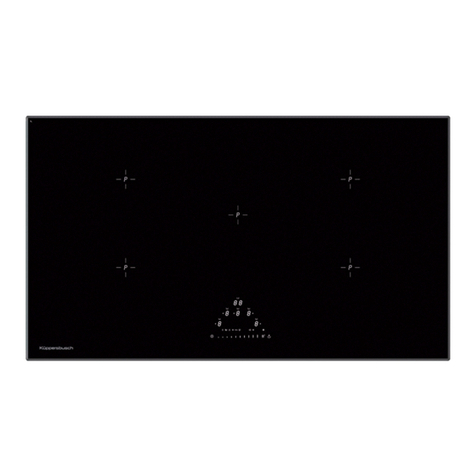
  9. Kuppersbusch EKE 81.2 Quick setup guide

Kuppersbusch EKE 81.2 Quick setup guide

BEDIENUNGSANWEISUNG
mit Montageanweisungen
Instructions for use and installation instructions
Instructions d’utilisation et avis de montage
Gebruiksaanwijzing en montagehandleiding
Istruzioni di uso e di montaggio
Instrucciones de uso y de montaje
Instruções de uso e de montagem
EKE 81.2
225059 M81
12 EKE 81.2
For your information
Please read the instructions in this booklet care ully as it contains important
in ormation concerning the sa ety, the installation, the use and the mainte-
nance o your appliance.
The appliance should only be used or cooking in the household.
Keep the operation instructions in a sa e place.
Notes on disposal
Disposing of the packaging
The transport packaging consists o the ollowing materials: Corrugated card-
board, cardboard, styro oam (CFC- ree), Polyethylen- oil.
Do not put these materials in the household rubbish, but ask your local au-
thority to give you the adress o the most convenient collection point.
What to do if you happen to have an old appliance
The symbol on the product or on its packaging indicates
that this product may not be treated as household waste.
Instead it shall be handed over to the applicable collection
point or the recycling o electrical and electronic equip-
ment. By ensuring this product is disposed o correctly, you
will help prevent potential negative consequences or the
environment and human health, which could otherwise be caused by inappro-
priate waste handling o this product. For more detailed in ormation about re-
cycling o this product, please contact your local city o ice, your household
waste disposal service or the shop where you purchased the product.
Conditions of guarantee
The conditions o guarantee applicable or this product are subject to those
published by the representative in the relevant country. Details regarding same
may be obtained rom the dealer rom whom the appliance was purchased.
For claims under guarantee the sales receipt must be produced.
Contents
Your appliance at a glance. . . . . . . . . . . . . . . . . . . . . . . . 13
Safety instructions . . . . . . . . . . . . . . . . . . . . . . . . . . . . . 14
or connection and unction
or the cooking area
Before first use . . . . . . . . . . . . . . . . . . . . . . . . . . . . . . . 14
Use of the cooking zones. . . . . . . . . . . . . . . . . . . . . . . . . 14
Switch on the hob
The cooking levels
Automatic initial cooking
Residual heat indicators
Multi-circuit cooking zones
Some instructions on cookware
The emergency switch
Sensor-lock
Timer
Time limit unction (holiday unction)
Other unctions
What to do if there is a fault . . . . . . . . . . . . . . . . . . . . . . 17
Cleaning and care. . . . . . . . . . . . . . . . . . . . . . . . . . . . . . 17
Installation. . . . . . . . . . . . . . . . . . . . . . . . . . . . . . . . . . . 18
Please note
Notes or itting
Installation
Electrical connection
EKE 81.2 13
Your appliance at a glance
1 Cooking zones
2 Cooking setting display o the cooking zones
3 Sensor keys or cooking zones
4 Minus sensor
5Plus sensor
6Sensor-lock
7 Sensor key ON/OFF
8Multi-circuit key
9Timer
10 Frying zone
11 Dual-circuitcooking zone
32
110
11
1
256789
4
14 EKE 81.2
Safety instructions
or connection and unction
■ The mains connection, maintenance and repair jobs should only be carried
out by an authorised technician in accordance with the applicable sa ety
standards. Work which has been improperly carried out can endanger your
sa ety.
■ The sur aces o heating- and cooking zones become hot during operation.
There ore: Always keep children away.
or the cooking area
■ Overheated ats and oils may spontaneously ignite. You should there ore
cook ood involving the use o ats and oils, e.g. chipped potatoes, only un-
der supervision. Never extinguish ats or oils with water! Place a lid on the
pan, switch o the cooking zone and take the pan o the hot cooking zone.
■ I cracks, ractures, or any other de ects appear in your glass-ceramic cook-
ing area, do not use your appliance. Unplug or otherwise disconnect your
appliance rom the mains supply and call our service centre.
■ I the cooking area cannot be switched o due to a de ect in the sensor
control immediately disconnect your appliance and call the service centre.
■ Be care ul when working with additional appliances! The connection leads
must not come into contact with the hot cooking zones.
■ The glass ceramic cooking area should not be used as a storage area.
■ Do not place combustible or in lammable objects upon the cooking top
which might be dangerous in case o unintentional switching on.
■ Never use the cooking zones without cookware. Never use the appliance to
heat rooms!
■ Never put aluminium oil or plastic on top o the cooking zones. Substances
that melt, or example plastic, oils and especially sugar and ood with a
high sugar content are to be kept away rom the hot cooking zone. In order
to avoid damaging, sugar, while still hot, should immediately be scraped o
the cooking area with a scraper.
■ Avoid repeated burning o stains and boiling over.
■ Chalk deposits may damage the cooking area.
■ I there are any pets in the apartment which could come near the hob, ac-
tivate the lock.
Before first use
Remove packaging and moving parts. Be ore irst use the cooking area should
be cleaned with a damp cloth and a little washing-up liquid.
The cooking area is insensitive to temperature shocks (cold and hot) and also
extremely robust.
■ Avoid dropping sharp objects onto the cooking area. Pointed objects alling
onto your cooking area might break it.
■ Please read through the cleaning and care instructions. Be especially care ul
to keep the sensor keys clean since soiling could be mistaken or inger
contact by the appliance. Never put anything (pans, tea towels etc.) onto
the sensor keys! I ood boils over onto the sensor keys, we advise you to
activate the emergency switch.
■ You might hear a humming sound rom the heating when switching on the
appliance. This is due to technical reasons and has no in luence on quality
and unctioning o your appliance.
■ Hot pans should not be put down near the sensor keys. In this case the
appliance may automatically shut o .
■ Clean the hob be ore using it or the irst time. Then switch the cooking
zones onto the highest setting, one a ter the other, or three minutes. This
will remove any “new” smell and cause any humidity in the heating units to
evaporate. This is necessary so that the electronic circuits unction properly.
Use of the cooking zones
Read the safety instructions!
Subsequent to initial connection and in the event o a power ailure, the con-
trols will be tested automatically. On completion o the test a short buzz will
sound.
Important:
There must be no objects on the sensors while the sensor sensitivity is being
set. Extreme lighting shining on the buttons, such as direct sunlight or bright
halogen lights, is to be avoided.
Switch on the hob
Touch sensor key ON/OFF
The cooking zone setting displays will indicate a “0” and the ready- or-
operation indications on the cooking setting displays will blink.
The appliance is in operation (stand-by mode).
The stand-by mode switches o automatically i no cooking zone is activated
within a period o 10 seconds.
EKE 81.2 15
The cooking levels
There exist 9 cooking levels.
A cooking zone is activated when the
cooking zone sensor key o the required
cooking zone is operated.
The spot at the bottom right o the cooking
setting display to indicate that a cooking
zone is ready or operation lights up.
The cooking setting o the
required cooking zone
can be activated by
means o the plus or the
minus sensors. The
setting is indicated in the
respective cooking setting
display.
I the plus sensor is
pressed, the cooking
zone will commence
operation at setting 1. I
the minus sensor is
pressed, the cooking
zone will commence operation at setting 9.
Switching o the selected cooking zone:
Press the minus sensor until the 0 setting is indicated,
or
press the plus sensor and the minus sensor simultaneously.
Automatic initial cooking
All cooking zones have a automatic
initial cooking unction. The
parboiling boost is activated at ull
power. The parboiling boost time
depends on the subsequent cooking
level which has been selected a ter
the activation.
The cooking zone automatically
changes to the selected subsequent
cooking level as soon as the set
parboiling boost time has elapsed.
Activate the required cooking zone by means o its cooking zone sensor key.
Select the cooking level 9 with the minus sensor.
The automatic parboiling unction is activated by touching the plus sensor. The
cooking setting display shows “A”.
The cooking setting subsequently required must now be set within
10 seconds.
The selected cooking level will be indicated alternately with an “A” on the
cooking level setting or as long as the automatic parboiling unction is
activated.
Should no subsequent cooking setting be selected within 10 seconds o
activating the automatic parboiling unction, the automatic parboiling unction
will be de-activated again.
Should the plus sensor be touched a ter the subsequent setting has been
selected, the parboiling boost time will be adapted to the newly-selected
subsequent cooking setting.
The automatic parboiling unction will be terminated i the minus sensor is
touched a ter the subsequent cooking setting has been selected.
Cooking level Suitable or
1-3 heating up, keeping warm
swelling, de rosting
4-5 steaming, soaking
boiling
6-8 rying, deep- at rying
9heating large quantities
or
and
Cooking
level
Parboiling
boost, time in
minutes:seconds
101:00
203:00
304:48
406:30
508:30
602:30
703:30
804:30
9– : –
16 EKE 81.2
Residual heat indicators
As long as the cooking zone is still hot an
“H” will appear in the display when the
cooking zone has been switched o .
Multi-circuit cooking zones
Usually the cooking zone with the smaller diameter is being heated.
Switch on the outer cooking zone circuit or bigger sauce pans or rying pans.
Dual-circuit cooking zones and frying zones
Two-circuit-circuit connection o the re-
spective cooking zone can only be e ected
a ter the corresponding cooking zone has
been activated and switched on.
Select the desired cooking level 1-9 .
Switch on the second heating element by
means o the Multi-circuit key. The control
lamp o the selected cooking zone lights
up.
The corresponding cooking zone must also be activated in order to switch o
the two-circuit connection. The outer heating circuits are switched o by pres-
sing the Multi-circuit key once again. The control lamps are then no longer lit.
Some instructions on cookware
Only use pans with even and flat bottoms.
Uneven pan bottoms prolong the boost times and increase the power require-
ment. Rough pan bottoms scratch the glass-ceramic area when shi ted about.
When using ireproo glass or porcelain cookware, please ollow the manu ac-
turers instructions.
Choose a pan with a diameter at least as large as the cooking zone.
You will thereby save energy and cooking time. You will also avoid overheating
o the cooking area.
Wherever possible, place a lid on the pan.
You will save a lot o energy by cooking in a closed pan. Liquids and oods
will only boil over i the temperature is too high. For the cooking zones, you
can precisely set the temperature required. With a little practice, you will read-
ily make the correct choice o cooking settings so that nothing boils over even
when a lid is in place.
The emergency switch
All o the cooking zones can be switched
o quickly by means o the ON/OFF
sensor.
Sensor-lock
The sensor lock can be used to protect the appliance against unauthorised
operation.
The ollowing unctions can still be used when the lock is activated:
■ emergency switch-o (ON/OFF sensor)
■ de-activating the lock
Activating the lock:
Press the lock sensor or
approx. 2 seconds.
The display on the bottom right below the
sensor will light up. The lock has been
activated.
De-activating the lock:
Press the lock sensor or
approx. 2 seconds.
The display on the bottom right below the
sensor will light up. The lock has been de-
activated.
Timer
The timer can be used to automatically switch o a cooking zone a ter a pre-
set time o between 1 and 99 minutes. The required cooking zone must be
activated, stand-by dot lights up. Select a cooking level rom 1 to 9 by means
o the minus or plus keys.
Then press timer key. The
timer display shows “00”.
Select the required cooking
time between 1 and 99 minu-
tes by means o the Minus or
Plus keys. The control lamp o
the selected cooking zone li-
ghts up.
The selected cooking time can be altered at any time. Activate the relevant
cooking zone, press timer key and change the cooking time by means o the
Minus or Plus keys.
EKE 81.2 17
When the pre-set cooking time has inished, the cooking zone switches o
automatically and an acoustic signal sounds or two minutes. This can be swit-
ched o by pressing any key.
I you want to switch the timer o be orehand, press cooking zone key and
timer key. The Minus key can now be used to set the timer to ”00”, or alter-
natively this can be done by the simultaneous pressing o the Minus and the
Plus keys.
The timer can also be used as an egg timer when none o the cooking zones
are activated. In this case, no cooking zone should be activated when the timer
is being set (the stand-by dot cooking zone does not light up).
Time limit unction (holiday unction)
The appliance is equipped with an automatic time limit unction. This unction
makes sure that the appliance is not in operation or a long time. The time
period o the time limit depends on the selected cooking setting, eg.: The high-
er the selected cooking setting, the aster the appliance is switched o
The unction to limit operation time works separately or each cooking zone.
Other unctions
■ I pressing two or more sensor keys – at the same time e.g. when a pan
is mistakenly put onto the sensor key no unction is activated. A ter 10 sec-
onds the appliance switches o automatically.
Exception:
– Switching o a cooking zone by means o simultaneously pressing the
plus and minus sensors.
■ The appliance does not automatically switch on again a ter a power ailure.
I the sensor lock was activated prior to a power ailure it will subsequently
be de-activated.
What to do if there is a fault
Unplug the appliance befor repair!
Check care ully to make sure that the ault is not due to misoperation. You
can recti y many aults yoursel .
Important note:
Repairs should only be carried out by an authorised technician! Even during
the guarantee period repairs will not be ree o charge i due to incorrect op-
eration or to non-adherence to our instructions given under “What to do i
there is a ault”.
You should always give the data on the rating plate to your service centre in
case you have enquiries or want to order spare parts. The rating plate is lo-
cated underneath the cooking area. The rating label is located at the bottom
side o the hob. It is also stuck onto the cover page o this operating manual.
Cleaning and care
■ Never use sharp or abrasive agents!
It is su icient to clean with a damp
cloth and a little washing-up liquid
a ter usage. Wipe dry.
■ Incrustation due to boilied over oods
are best preso tened with a wet
cloth. Then remove them with a glass
scraper. Sugar and melted plastic
should be removed while the cooking
area is still hot.
■ Clean the glass-ceramic cooking area a ter every use. Always keep the sen-
sor keys clean, since soiling could be detected as inger contact by the
aplliance. Immediately remove soiling. Never put anything (pans, tea-towels
etc.) on the sensor keys! I ood boils over onto the sensor buttons, we ad-
vise you to activate the emergency switch.
■ Care or your glass-ceramic cooking area once a week. Regular care builds
up a protective layer and also eases day to day cleaning. Please ollow the
instructions o the cleaner or cleanser manu acturer concerned. Even heavy
soiling can be cleaned with a cleanser and enough water. Wipe dry with a
cloth.
Cooking setting Switching o time a ter
9
8
7
6
1.5 hours
54 hours
4
35 hours
2
16 hours
Fault Cause Remedy
Not possible to
switch o cooking
area.
Failure o electronic
component.
Switch o cooker use in use-
box, Call service centre.
The LED indicator or
the cooking level or
heat indicator does
not light up or only
partly lights up.
LED indicator de ec-
tive.
Call Customer Service. There is
a danger o being burned as the
temperature warning is not
reliable.
Cooking area does
not heat.
Fuse is de ective. Check or replace cooker use in
use box.
Sensor lock not de-
activated.
De-activate the sensor lock.
Cooking area is
de ective.
Call service centre.
18 EKE 81.2
Installation
Please note
KÜPPERSBUSCH built-in cooking zones may be combined only with KÜPPERS-
BUSCH built-in ovens with cooling an. The use o any other make o oven
shall exempt Küppersbusch rom all liability. Failure to observe this requi-
rement will invalidate all granted certificates and labels of approval.
Notes or itting
■ Make sure that the worktop is per ectly horizontal.
■ The ront, rear and lateral clea-
rances around the hob unit must
be maintained in accordance with
the dimensional drawing.
A corner moulding o solid wood
may be itted to the worktop at
the back o the hob unit provided
that the minimum clearances are
maintained.
For practical reasons the lateral
clearance between the hob unit
and an adjacent tall cupboard unit
must measure at least 300 mm.
■ Make sure that there is su icient clearance underneath the cut-out. Any ur-
niture battens must be cut away to leave an area which is at least the same
size as the cut-out itsel .
■ Make a point o ensuring that the plastic laminate or wood veneer on your
urniture surround has been applied by means o a heat-resistant adhesive
(100 °C).
■ The underside o the in-
stalled appliance must be
protected by a panel which
prevents inadvertent con-
tact with the live parts or
connecting leads between
the control unit and the
hob unit.
It must not be possible to
remove the panel without
tools.
■ Any cooker hoods or wall
cupboards must have a
vertical clearance o at least 650 mm rom the hob unit.
■ Miniumum distance rom the hob edge to the adjacent wall: 40 mm.
It will be expedient to seal built-in sinks and other built-in appliances in the
worktop in the same way (protection against ingress o water).
We recommend you to seal the cut sur ace o the worktop recesses or itted
sinks and hobs with a protective water-proo paint.
The assembly seal is to be renewed a ter every dismantling operation. You can
obtain this sealing rom our Customer service.
Installation
■ Be extremely care ul when installingl Do not place or drop any sharp or
pointed tools (screwdrivers etc.) on the glass sur ace!
■ The glass-ceramic cooking area must have a level and lush bearing. Any
distortion may lead to racture o the glass panel.
■ Never use any electrically operated or air operated wrenches and avoid any
overtightening!
Making the worktop recess
– Make the worktop recess accurately with a good, straight saw blade or re-
cessing machine in accordance with the dimensions in the illustrations. The
cut edges should then be sealed so that no moisture can penetrate.
490± 1,0
730
±1,0
730
±1,0
750
510
50
55
EKE 81.2 19
Insert the hob
– Care ully position the hob in the recess and irmly asten to the worktop with
the appropriate attachment elements.
– A ter attachment check the seal with the worktop.
Attachment with screws
– Insert the angle nuts and introduce the glass ceramic hob rom above. Then
asten the hob with screws and attachment brackets rom below (see illu-
strations).
– Align the glass ceramic hob horizontally. There is a risk o breakage i the
hob is canted or subjected to stress during installation!
Attachment with clips
Drive in the clips
– Align the clips care ully and drive them in with a hammer..
Worktops with more than 30 mm thickness:
With worktops with 30 mm
thickness the clips have to be
screwed down with two screws
(not supplied)!
Inserting the hob
– Position the hob on the le t side
(1), align it (2) and insert the
clips (3).
Be care ul not to pinch the
connecting cable!
=It is essential that the hob
rests evenly in the opening,
since strain may cause the
griddle/hob to crack on being
heated up.
F I the hob is not ixed tightly in the opening
it is slightly too big. In this case screw the
clips with two screws down each (not supp-
lied) to raise the spring tension.
Plug the mains plug into the wall socket.
– Insert the plug into the wall socket.
– The exceeding cable has to be pulled out o the installation area.
Attachment of worktops with an uneven surface
– When installing a hob into an uneven worktop, e.g. with a ceramic or similar
covering (tiles etc.), the seal on the hob is to be removed and the seal bet-
ween the hob and worktop made with plastic sealing materials, such as
heat-resistant silicone rubber (not included in scope o delivery).
– Clean the sur aces to be sealed in accordance with the manu acturer's in-
structions on the cartridge. Apply the compound in a continuous strip, pres-
sing it irmly against the gap to be sealed.
217,5 217,5295
217,5 217,5295
20 EKE 81.2
Electrical connection
■ The built-in cooking area must be connected to the mains supply by
a qualified electrician who is authorized to carry out such work.
■ Both legal wiring regulations and the requirements o your local electricity
supply board must be ully complied with.
■ When connecting the hob, a device must be provided which enables all-
pole disconnection o the hob rom the supply with a gap construction o at
least 3 mm. Circuit breakers, uses and contactors are considered to be
suitable disconnecting units.
■ When connecting and repairing the appliance disconnect it rom the elec-
tricity supply with one o these devices.
■ Overall protection against electric shock must be ensured by the installation.
■ The earthed conductor lead must be su iciently long so that, in the event
o ailure o the strain relie , it is not subjected to strain until a ter the live
wires o the connection cable.
■ Any super luous cable must be removed rom the installation area beneath
the appliance. See the illustration on page 18 or the position o the cable
cut-out.
To connect the appliance, unscrew the switchbox cover on the underside o
the appliance to access the terminal block. A ter connecting the appliance, re-
place the cover and secure the connection cable with the strain relie clamp.
■ The green-yellow earth conductor must be longer than the other wires.
Electrical connections
Caution:
Incorrect connection results in the total destruction of the power elec-
tronics.
Electrical
connection
Permanent connection by means o an oven connection
socket.
Connection
diagram
is depicted on the underside o the appliance, suitable or
the various types o mains.
Connection data Permanent connection 400 V 3 N ~ 50 Hz
(AC 230 V in UK)
Voltage o heating element: 230 V
Total connection output: 7.6 kW
400 V 3 N ~ sa ety current 16 A
400 V 2 N ~ sa ety current 20 A
230 V 1 N ~ sa ety current 25 A
Connection cable at least o type HO5 VVF
Length o cable as necessary.
(*) This type o electrical connection is not permitted by the SEV (Swiss As-
sociation o Electrical Engineers) in Switzerland.

Other Kuppersbusch Hob manuals

Kuppersbusch EKI9954.1F Operation manual

Kuppersbusch

Kuppersbusch EKI9954.1F Operation manual

Kuppersbusch EKI9940.1 User manual

Kuppersbusch

Kuppersbusch EKI9940.1 User manual

Kuppersbusch GKS 324.0 User manual

Kuppersbusch

Kuppersbusch GKS 324.0 User manual

Kuppersbusch EKS Series Use and care manual

Kuppersbusch

Kuppersbusch EKS Series Use and care manual

Kuppersbusch KI9520.0SF Operation manual

Kuppersbusch

Kuppersbusch KI9520.0SF Operation manual

Kuppersbusch EKE 854.2 Operation manual

Kuppersbusch

Kuppersbusch EKE 854.2 Operation manual

Kuppersbusch EKE 60.2 Quick setup guide

Kuppersbusch

Kuppersbusch EKE 60.2 Quick setup guide

Kuppersbusch EWE 457.1 User manual

Kuppersbusch

Kuppersbusch EWE 457.1 User manual

Kuppersbusch GKS 324.0-54 User manual

Kuppersbusch

Kuppersbusch GKS 324.0-54 User manual

Kuppersbusch EKE 61 Quick setup guide

Kuppersbusch

Kuppersbusch EKE 61 Quick setup guide

Kuppersbusch EWI 456.0 Quick setup guide

Kuppersbusch

Kuppersbusch EWI 456.0 Quick setup guide

Kuppersbusch VKIW3800.0 Operation manual

Kuppersbusch

Kuppersbusch VKIW3800.0 Operation manual

Kuppersbusch EKE 805.3 Quick setup guide

Kuppersbusch

Kuppersbusch EKE 805.3 Quick setup guide

Kuppersbusch VKI3805.0 User manual

Kuppersbusch

Kuppersbusch VKI3805.0 User manual

Kuppersbusch EKE3721.1 Operation manual

Kuppersbusch

Kuppersbusch EKE3721.1 Operation manual

Kuppersbusch KI6120.0SR Operation manual

Kuppersbusch

Kuppersbusch KI6120.0SR Operation manual

Kuppersbusch VKE3300.0SR User manual

Kuppersbusch

Kuppersbusch VKE3300.0SR User manual

Kuppersbusch K8 Operating and maintenance manual

Kuppersbusch

Kuppersbusch K8 Operating and maintenance manual

Kuppersbusch EGE3710.1ED Operation manual

Kuppersbusch

Kuppersbusch EGE3710.1ED Operation manual

Kuppersbusch EGS 304.0 User manual

Kuppersbusch

Kuppersbusch EGS 304.0 User manual

Kuppersbusch KI6870.0SR Operation manual

Kuppersbusch

Kuppersbusch KI6870.0SR Operation manual

Kuppersbusch EKI9652.1 Operation manual

Kuppersbusch

Kuppersbusch EKI9652.1 Operation manual

Kuppersbusch GWS 3711.0ED Troubleshooting guide

Kuppersbusch

Kuppersbusch GWS 3711.0ED Troubleshooting guide

Kuppersbusch EKRS 600.0 Quick setup guide

Kuppersbusch

Kuppersbusch EKRS 600.0 Quick setup guide

Popular Hob manuals by other brands

Gaggenau SP 483 Operating and assembly instructions

Gaggenau

Gaggenau SP 483 Operating and assembly instructions

Bosch PCQ875B21E/01 instruction manual

Bosch

Bosch PCQ875B21E/01 instruction manual

Waterline essentials ESSGH60E Users guide & installation handbook

Waterline

Waterline essentials ESSGH60E Users guide & installation handbook

Electrolux EIV84550 user manual

Electrolux

Electrolux EIV84550 user manual

Kaiser KCT 4745 F user manual

Kaiser

Kaiser KCT 4745 F user manual

Smeg P1752XTD manual

Smeg

Smeg P1752XTD manual

ROSIERES RPI430 Instructions for use and installation

ROSIERES

ROSIERES RPI430 Instructions for use and installation

Hotpoint IX 644 CRFH operating instructions

Hotpoint

Hotpoint IX 644 CRFH operating instructions

Bosch PEE68.CA1 instruction manual

Bosch

Bosch PEE68.CA1 instruction manual

Beko GIEI627474PN installation instructions

Beko

Beko GIEI627474PN installation instructions

AEG IKE42640KB user manual

AEG

AEG IKE42640KB user manual

Ariston PKL 751 A operating instructions

Ariston

Ariston PKL 751 A operating instructions

Gaggenau CI 490 use and care manual

Gaggenau

Gaggenau CI 490 use and care manual

Bosch PIE975N14E instruction manual

Bosch

Bosch PIE975N14E instruction manual

AEG IKE84475FB user manual

AEG

AEG IKE84475FB user manual

Lamona LAM1006 user guide

Lamona

Lamona LAM1006 user guide

IKEA LAGAN user manual

IKEA

IKEA LAGAN user manual

Smeg SE264SX3 manual

Smeg

Smeg SE264SX3 manual

manuals.online logo
manuals.online logoBrands
  • About & Mission
  • Contact us
  • Privacy Policy
  • Terms and Conditions

Copyright 2025 Manuals.Online. All Rights Reserved.