Point Source Lighting Westwood, New Jersey 07675 Fax 201 664 4801
INSTALLATION INSTRUCTIONS
SQUARE DIRECTIONAL
J2333, J2335, & J2337
Junction
Box Inner
Cover
T
-approx. 1/4"" Jlh dlrecllons
(left to right / forward and backward)
Note: If required: I
Fig. 1
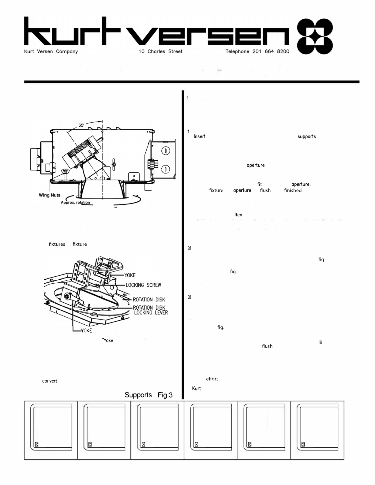
Before ceiling is closed, loosening of wing nuts
allows square aperture to be aligned with other
in pattern. Re-tighten wing nuts
when desired alignment is attained.
LOCKING LEVER
Fig. 2
1 For adjustable units, releasing Locking Lever• allows
yoke to pivot from O to 35 degrees (Modules142, 144,
and 146. 0 to 25 degrees for module 248). Re-engage
lever when desired angle is obtained.
2 Releasing "Rotation Disk Locking Lever• allows rotation
disk to rotate 360 degrees. Re-engage lever when
desired position is obtained.
3 To from downlight to adjustable position, remove
downlightlocking screw.
Rail
1-1 /2" channel1• channel 1/2" conduit
Notes:
Installationby a licensed electrician only. Make sure power is off.
Building wires must be in compliance with local codes.
2 Rails are not supplied unless ordered. They come in two sizes
26" and 52". Contact the factory. Available immediately.
3 Fixture must be above ceiling before closing in.
Installation
Fasten rail supports to internal adjustment brackets on housing.
rails by gently squeezing wings of rail
together to ease passage of rails. Do not squeeze too hard or
the rail supports will take a set. When pressure is released, the
rail support will lock onto rails. (See Fig. 3)
2 Remove proper knockouts from junction box and attach connectors.
3 If alignment of square is required, with trim removed, loosen
(2) wing nuts. Align aperture. Tighten wing nuts. {See Fig. 1)
4 Using the aperture as a template, mark tile for the aperture hole.
5 Cut hole in tile for a snug around the
6 Adjust so is with tile face or 1/16"
above. Do not allow aperture edge below tile face or more than
1/16" above. Tighten rails to ceiling grid permanently. {See Fig. 7)
Wiring
1 Attach conduit or to junction box. Make all splices.
2 Fixture must be grounded with greenscrew or groundingwire provided.
Installation of LED Module Assembly:
Downlight Position. {See Fig. 4)
Fixtures are pre-set at the factory in the downlightposition per order.
Push in LED wire plug into pin plug in driver plate.
3 Engage LED module bracket into yoke until springs engage into slots.
4 When required, yoke may be rotated horizontally. {See . 2)
5 To remove, unplug module. Depress spring. Pull module gently
form yoke {See 6).
Installation of LED Module Assembly:
Adjustable Position. {See Fig. 4)
Place yoke in vertical position.
Push in LED wire plug into pin plug in driver plate.
3 Engage LED module bracket into yoke until springs engage into slots.
4 Adjust vertical and horizontal positions as desired. Lock in place with
locking levers {See Fig. 2).
5 To remove, unplug module. Depress spring. Pull module gently from
yoke {See 5).
Installation of Trim. (See Fig. 4)
1 Squeeze springs on either side of trim and attach safe chain.
2 Insert trim into aperture until with ceiling on all s,des.
Access to Junction Box: {See Fig. 1)
Remove trim (disconnect safety chain) and LED module inside yoke,
release wire plug remove inner junction box cover.
Quality Control
Every is made to assure that our products reach the job
in perfect condition. We welcome your comments.
Versen Company may change construction periodically without
notice as part of its program for product improvement.
1/2" bar 1• bar 1/2" - 1• angle
Supports accept many types of roils. Job site scrap may be used. KV3547 Union mode IBEW.


