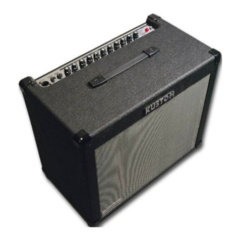
Kustom Defender V30 User manual

V30
OWNER’S MANUAL
GUITAR AMPLIFIER
Congratulations on the purchase of your Kustom Defender V30.
Your Defender Model draws on decades of amp design and manufacturing experience at Kustom. This model was built from the ground
up to offer world-class tone, useful features and reliable performance. Inside this manual, you’ll nd valuable information about the
amp’s controls and specications. Being familiar with its features will help you effectively dial in different tones. We wish you many
years of enjoyment with your Kustom amplier.


5. MASTER BYPASS: This control disables the Master Volume control from the circuit, allowing the V30 to function like a vintage tube
amp. Crank up the Volume Control with Master Bypass engaged for authentic vintage overdrive.
1 2 3 4 5 6 7 8 9 10 11
12
14
13
6. BASS: This passive EQ adjusts the low frequency equalization of the amplier. It interacts with the Middle and Treble as described
in the Treble section (8). For a tighter low end, use the Bass EQ set to lower settings. This is particularly helpful when using the amp at
very loud settings.
1. INPUT JACK: This ¼” input is for plugging in your instrument. It is intended for guitar but will accept other instruments as well.
3. VOLUME: This control adjusts the gain at the input stage of the preamp. It is used in conjunction with the Master to dial in the
desired amount of distortion and volume. For cleaner sounds, this control should be set to lower settings and the Master set higher for
slight breakup, the controls should be set in their middle ranges for heavier distortion, set the Volume higher and the Master lower.
2. BRIGHT: The Bright Switch increases the high frequencies while reducing low frequencies for a tighter, chunkier attack. This feature
is useful for ne-tuning the amp’s tone and feel for different guitars.
4. MASTER: The Master control sets the overall volume of the amplier and simultaneously tailors the tone controls based on the
Master knob position. When the Master is set higher, the tone is adjusted for a cleaner, “chimey” tone. When set lower, for more
distortion, the tone controls adjust the low end for a tighter, thicker sound.
7. MIDDLE: This passive EQ adjusts the midrange equalization of the amplier. It interacts with the Bass and Treble EQ as described
in the Treble section (8). For a heavier, more distorted sound, set the Middle lower. For more of a vintage-style, cleaner sound, set the
Middle higher. This EQ works for both Rhythm and Lead channels
8. TREBLE: This passive EQ adjusts the high frequency equalization of the amplier, but also interacts with the Bass and Middle
controls as follows: As the Treble is increased, the Bass automatically decreases and the Middle slides down in frequency. Conversely,
if the Treble is decreased, the Bass automatically increases and the Middle slides up in frequency. This interaction is typical of vintage-
style passive EQ, and is responsible for the increased effectivity of such a simple system.
9. REVERB: Reverb controls the amount of reverberation effect in the amplier. This effect is created by an authentic spring reverb pan
and essentially sounds like playing the amp in a large room. The Reverb can be defeated by turning the knob fully counter-clockwise.
10. PRESENCE: The Presence control operates in the power amp section of the amp and adds high frequencies to the tone. Higher
settings will provide more bite and help you cut through the mix.
11. BOOST: This controls the amount of footswitchable boost in the power amp, and is particularly useful for solos. It will provide up to
10dB of “Master Volume” boost. The tone is optimized to increase the volume without sacricing too much headroom in the power amp.
(Note: Boost is active if the footswitch is unplugged.)
12. JEWELED PILOT LIGHT: Indicates that the power switch is in the “ON” position.
13. STANDBY: This allows the amplier to be on, but with the tubes in a non-operational mode. Switching into the “OFF” will cause no
sound to come out of the amplier. This can be used instead of the power switch between performance sets, and when powering up the
amp.
14. POWER: Provides AC power to the amplier when in the “ON” position.
V30 Control Panel

1 2 3 4
A BC
D E 5
6
7 8
1. AC POWER CORD RECEPTACLE: Insert the AC cord (provided) rmly into the AC connector. NOTE: Replace the AC power cord if
protective jacket is damaged or ground pin is damaged or removed. The fuse is located in a housing just below the receptacle. Replace
only with same type and size. To remove the fuse, remove AC power cord and pull out on the tab above the fuse symbol located on the
fuse carriage. Place the new fuse in the carriage clip and re-insert.
NOTE: To prevent an electrical hazard, DO NOT replace fuse without using the fuse carriage. Replace the fuse carriage if lost
or damaged before re-inserting the AC power cord.
3. FOOTSWITCH: The Footswitch jack on the V30 is a mono jack that connects to a footswitch to the amplier. The footswitch switches
the Boost on and off.
2. FUSE: The fuse is located in a fuse tray just below the receptacle. Replace only with the same type and size. For your convenience,
a spare fuse is located inside the fuse tray toward the front. To replace fuse, remove AC power cord.
Remove fuse tray by pulling the tab located above the fuse symbol away from the receptacle.
5: SPEAKER OUTPUTS: These 1/4” jacks are provided to connect the internal and/or external speakers to the V30.
THE AMPLIFIER SHOULD NEVER BE OPERATED WITHOUT A SPEAKER PLUGGED INTO A SPEAKER JACK.
6: IMPEDANCE SELECTOR: This switch is used to select the appropriate impedance, and is important in achieving the desired results
from the V30. The correct impedance should be selected using the Impedance Selector Switch as follows:
A. Internal Speaker Only: 16 Ohm Setting
B. Internal Speaker + External 16 Ohm Speaker: 8 Ohm Setting
C. Internal Speaker + External 8 Ohm Speaker: 4 Ohm Setting. (This conguration results in a mismatched impedance)
7. DIRECT OUT: The XLR Direct Out jack is designed to connect the V30 amplier to a recording or live mixer. The output is speaker-
emulated, and mimics the sound of the Celestion Vintage loudspeaker. This output is very useful for direct recording, and especially
helpful for live applications since it eliminates a live microphone on stage and the resulting feedback potential. The V30 amplier should
never be operated without a speaker plugged into a speaker jack.
8. GROUND LIFT: The Ground Lift switch disconnects pin 1 of the XLR Direct Out jack to eliminate a “ground loop” hum. A ground loop
can exist when the V30 and the mixer it is plugged into are connected to grounded outlets that are in physically different locations and/
or on different circuits, and should only be used if there is an audible hum. Pressing the ground lift does not disconnect the ground
connection from the V30’s chassis.
4. TUBE CONFIGURATION DIAGRAM
A. Bias Switch: The V30 ships from the factory with classic EL34 output tubes. However, if you want to try 6L6’s, this amp has the
capability. Underneath the tube cage is a switch that may be used to change the bias to accommodate either EL34 or 6L6 power tubes.
(Note: This switch is not a user serviceable item. Be sure to take it to a qualied service tech to make these changes.)
B. EL34 Output Tubes: These power tubes were selected to provide the best combination of performance and tube life, and shouldn’t
require adjustment to their bias. The amp uses a mixed-bias system, which is a combination of xed and self-bias techniques to give
the user the best of both worlds. The result is that the amp will control its own bias to a certain extent, but without the typical reduction
in power associated with normal self-biased designs. The V30 uses two EL34s in a “push-pull” amplier conguration.
C. Phase Inverter Tube: This 12AX7 is used in boosting the gain and driving the EQ. It has the biggest impact on higher gain sounds.
D. Preamp Tube 2: This 12AX7 is used in boosting the gain and driving the EQ. It has the biggest impact on higher gain sounds.
E. Preamp Tube 1: Half of this 12AX7 is the input tube, and as such, is the most likely to cause microphonic problems. If tube feedback
occurs, it can usually be corrected by swapping this rst tube with one of the other tube locations, since they have less gain following
them and are less prone to feedback. The rst tube also has the greatest effect on the clean tone of the amp. The other half of this tube
is responsible for providing the extra gain needed for the Boost control.

V30 Specications

Signal Flow Diagram

EC Declaration of Conformity
We: Kustom Musical Amplification INC.

3015 Kustom Drive
Hebron, Ky 41048-0568
Tel: 1-859-817-7100 Fax: 1-859-817-7150
Declare that the product
Product name:
Product model number:
to which this declaration relates is in conformity with the following standards;
EN55013: 2001/+A1:
2003+A2: 2006 Limits and methods of measurement of radio disturbance characteristics of broadcast
receivers and associated equipment.
EN55020: 2007 Electromagnetic immunity of broadcast receivers and associated equipment.
EN61000-3-2: 2006 Limits for harmonic current emissions (equipment input current < 16A per phase).
EN61000-3-3: 2008 Limitation of voltage fluctuations and flicker in low voltage supply systems for
equipment with rated currents < 16A.
EN60065: 2002+A1:
2006+A11: 2008 Safety requirements for main operated electronic and related apparatus for household and
similar general use.
Following the provisions of EU Council Directive(s): 72/73 EEC and 89/336/EEC.
We the undersigned, hereby declare that the equipment specified above conforms to the aforementioned directive(s).
Name of authorized person: James Brown, Chief Engineer
Signature:______________________ Date:
Kustom Musical Amplification INC.
3015 Kustom Drive
Hebron, Ky 41048-0568
Tel: 1-859-817-7100 Fax: 1-859-817-7150
Signature:______________________
Date:
Defender V30
March 15, 2011
Kustom


www.kustom.com
3015 Kustom Drive
Hebron, Kentucky
USA 41048
888-4-KUSTOM (888-458-7866)
Table of contents
Other Kustom Musical Instrument Amplifier manuals

Kustom
Kustom KXB100 User manual

Kustom
Kustom KG112FX User manual

Kustom
Kustom KB200 User manual

Kustom
Kustom Sienna30 User manual

Kustom
Kustom Defender V50 User manual

Kustom
Kustom KG1 User manual

Kustom
Kustom GROOVE 1200 User manual

Kustom
Kustom KGA30 User manual

Kustom
Kustom KG210FX User manual

Kustom
Kustom 72 Coupe Hardtop Quick start guide

Kustom
Kustom 36 coupe User manual

Kustom
Kustom The Defender V5 User manual

Kustom
Kustom Sienna16 User manual

Kustom
Kustom IV Lead User manual

Kustom
Kustom KAA65 User manual

Kustom
Kustom III User manual

Kustom
Kustom Sienna 35PRO User manual

Kustom
Kustom HV 30 User manual

Kustom
Kustom DE300 HD User manual

Kustom
Kustom KGA10 User manual