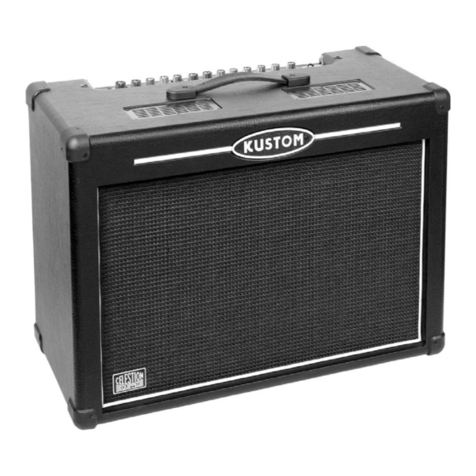
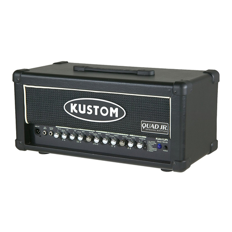
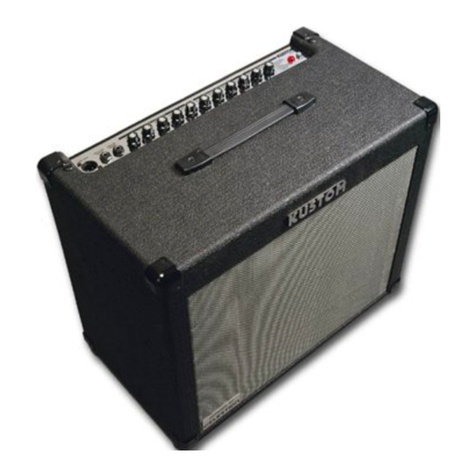
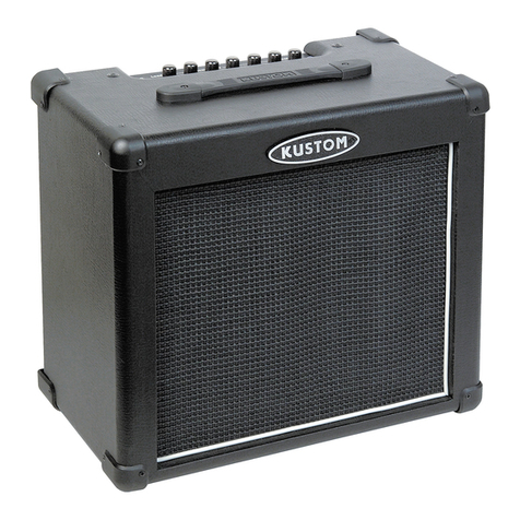
Kustom IV Lead User manual

www.SteamPoweredRadio.Com
KUSTOM
WARRANTY
All
Kustom amplifi
ers,
poweruni
ts,
mixers, and
their
associated components and
part
s, except
as
specilied below, are
guaranteed, by Kustom Electronics, Inc
.•
to
the original purchaser
to
be free of defects
in
material
or
workmanship for a
per
iod
of five
(5)
years from
the
date
of purchase.
-and -
All
Kustom speaker cabinets and their associated components and parts, except as specified below, are guaranteed, by
Kustom Electronics, In
c.,
to
the
original purchaser
to
be free ofanydefects in materials and workmanship for a period
of
one
(1)
year from the
date
of purchase.
-provided -
(I) Theoriginal pu
rc
h
aser
applies for a Kustom Warranty Card for
the
guaranteed product(s) within
10
days ofthe
date
of purchase; and,
(2)
Within the applicable period of this guarantee,
the
original purchaser deliver
s,
at
his own expense. the defective
product(s)
to
an Authorized Kustom Dealer
or
Service Center
fo
r repair; or, where no such dealer
or
se
rvice center
is nearby, obtains
at
his own expense from Kustom Electronics, Inc., a.n "Authorization Number"
to
return
merchandise and ships,
at
his own expense,
the
defective product(s)
to
Kustom Electronics Customer Service,
909
W. Che
rr
y,
Chanu
te,
Kansas 66720. The repaired product(s) will
be
returned freight prepaid.
Kustom Electronics, Inc., will,
at
its
option, repair
or
replace
the
defective part(s)
or
product(s).
Excluded from coverage by this warranty are exterior
su
rfaces and finishes, face panels, grill cloth, covers, knobs,
handles, casters and appearance items.
Any modification of
the
Kustom-manufactured product(s) such
as
the
installation ofsubstitute parts, rewiring
or
other
changes
to
the
system without written
aut
horization from Kustom Electronics, Inc.,
will
automatically void this warranty.
Kustom Electronics, Inc., shall not be liable
fo
r any direct, special, incidental
or
consequential damages incurred
by
reason of a breach of the above provisions, except as expressly provided above.
The provisions of this warranty shall be covered by the local laws of
the
state
where
the
original purchaser shall
purchase products covered hereby, and shall be en
fo
rceable only
to
the
exte
n
t,
and in
the
manner, permitted under such
laws.
EXCEPT
AS
HER
E
IN
E
XPRESSLY
PROVIDED
,
KUSTOM
ELECTRONICS,
INC.,
MAKES
NO
WARRANTY
,
EXPRESSED
OR
IMPLIED
,
OF
MER
C
HANTABILITY
, FITNESS
FOR
A
PA
R
TICULAR
PURPOSE,
OR
OT
HER
WISE
.
www.SteamPoweredRadio.Com
CONTROL OPERATION
CHANNEL
I - LEAD
The Kustom IV
Lead
electric guitar amplifier is designed
with
one
of
the most flexible
electronic control systems available.
The Channel I preamplifier includes a non-linear device which
can
be used to introduce a
deliberate, controlled distortion into the music. Located in the circuit between the DRIVE and
VOLUME controls, the device receives its signal from the DRIVE circuit.
In
this manner, a high
DRIVE setting causes more distortion, independent
of
the VOLUME setting. As a result, the
VOLUME setting to produce a given outputwill depend on the DRIVE control setting. DRIVE and
VOLUME controls should
be
used together to obtain a type
of
distortion similar to certain older
tube-type amplifiers. To achieve this sound, adjust both controls so that the desired amount
of
distortion is achieved
at
the required volume level. With the DRIVE control adjustep maximum
counter-clockwise, distortion will be at a minimum.
Distortion occurs
in
the preamplifier and
not
in the output or final stages. Output distortion
will
be
obtained only at high power and volume levels and has a distinctly different sound.

www.SteamPoweredRadio.Com
The BASS, MIDDLE, and TREBLE controls are
of
the
"boost
and
cut"
configuration, and
exhibit a great deal
of
control over their operating ranges. However, the type
of
guitar, strings,
and playing style will have a noticeable effect on the tone control operation. The electric guitar
has a frequency range
of
from approximately 74Hz (open
low
El
to
1320Hz (12th fret high
El
. The
dominant harmonicovertones occurin the frequency range
of
128Hz -528GHz. The relationship

between the fundamental frequency and the harmonics determine the tonal quality
of
the
amplified sound. The tone control circuitry provides the musician
with
the means to control the
amplitude relationship between these frequencies.
The tone control circuits are configured very much like those used on the older tube-type
amplifiers. i:his arrangement has the advantage
of
unique boost and cut points and the
disadvantage that if all three tone controls are adjusted
to
minimum, no output signal will result.
The
BR
IGHT switch located on the TREBLE control (pull
for
"on")providesavery noticeable
increase in the extreme treble when the VOLUME control is advanced past position 5.
Tremolo
SPEED
and DEPTH controls are used to adjust the rate and effect
of
the tremolo
circuitry. The tremolo
SPEED
control adjusts the rate at which the tremolo circuits vary the
intensity
of
the amplified signal. The
SPEED
control will only function when the tremolo foot
switch has been depressed and the
DEP
TH control advanced
to
a r.iominal operating position
(5)
.
The tremolo DEPTH control adjusts the amount
of
effectthetremolo circuitry has on the amplified
sound.
The R
EVER
B control adjusts the amount
of
artificial reverberation mixed with the input
signal. As the control is advanced in the clockwise direction, more
of
the reverberation effect
results. When thecontrol is
ad
justed
to
minimum, the reverb spring will
not
crash or rumble when
the amplifier is moved or shaken.

www.SteamPoweredRadio.Com
CHANNEL
II
-
NORMAL
Channel
II
allows modified tone control action (for a bass guitar) and also allows proper
equalization for a standard electric guitar.
The electricguitar has a frequency range
of
from approximately74Hz (open
low
E)
to 1320Hz
(12th fret high El. The dominant harmonic overtones occur in the 128-5280Hz frequency range.
The relationship between the fundamental frequency and these harmonics determine the
tonal quality
of
the amplified sound. The tone control circuitry provides the musician with the
means
to
control the relationships between these frequencies.
The tone control circuits for the electric guitar
c;He
configured very much like those used on
the older tube-type amplifier. This arrangement has the advantage
of
uniqueboost and cut points
and the disadvantage that
if
all controls are adjusted
to
minimum, no output signal results.
Channel
II
tonecontrol circuits, like those used in Channel I, can only
c::ontrol
the frequencies
within their operating range. However, control action for
an
electric guitar will be more apparent
under mostoperating conditions than
for
the electric bass, because
of
the ability
of
the guitar to
play chords.
The strumming
of
an
electric guitar produces an extremely complex signal which, in most
instances, has a fundamental frequency and
at
least one harmonic overtone in each
of
the tone
control operating ranges.

www.SteamPoweredRadio.Com
OPERATING CONTROLS
CHANNEL
I - LEAD
Dr
ive
Used in conjunction with the VOLUME control to produce a form
of
distortion
usually associated with tube-type amplifiers.
With
the DRIVE control adjusted
to
minimum, a very clean sound results. In normal operation, the DRIVE and
VOLUME controls are adjusted to achieve thedesired distortion at any volume level.
Volume
Adjusts the loudness
of
the amplifier. Depending on the instrument used,
maximum amplifier output can be obtained at almost any control setting. Control
numbers are provided for
ease
in readjusting the amplifier for a specified output
level.
Bass
Adjusts the level
of
the
"low
end"
or
bass frequencies. This control is
of
the "boost
and
cut"
-type.
Middle
This
"boost
and
cut"
-type control adjusts the level
of
the frequencies
in
relation to
the
bass
and middle frequencies. TREBLE
is
also the
"boost
and
cut"
-type control.
Treble
Used to adjust high frequencies in
re
lation to
bass
and middle frequencies. A
"boost
and
cut"
-type control.
Bright
Located on the TREBLE control, the BRIGHT switch provides an additional degree
of
"bite"
or boost to the treble frequencies. Pull for
''on"

www.SteamPoweredRadio.Com
Speed Adjusts the rate
at
which the tremolo circuits vary the intensity
of
the amplified
signal. This control will only function when the tr3molo
foot
switch has been
depressed and the DEPTH control advanced
to
a nominal operating position
(approximately 5).
Depth
Controls the amount
of
effect the tremolo circuitry has on the amplified sound.
Tremolo circuitry varies the amplitude
or
strength
of
a signal
as
compared to a
vibrato circuit which actually alters the.physical pitch
of
a note.
Reverb Controls the amount
of
artificial reverberation mixed
with
the input signal. When
the control
is
at
the minimum setting, the reverb spring will not
"crash"
when the
amplifier is moved
or
shaken.
CHANNEL
11
-
NORMAL
Volume
Same
as
Channel I VOLUME control.
Bass Operates the same
as
Channel I BASS, except that the boost and
cut
points are
modified to resembl~ those
of
older tube-type amplifiers.
Middle
This
"boost
and
cut"
-type control affects frequencies in
the
middle
of
the electric
guitar range. Control action resembles that
of
a tube-type amplifier.
Treble A
"boost
and
cut"
-type control, its action also resembles
that
of
a tube-type
amplifier and functions the same
as
Channel I TREBLE control.
Bright Operates the same
as
Channel I BRIGHT control.

www.SteamPoweredRadio.Com
GENERAL CONTROLS
Master
Volume
Graphic
Equalizer
Controls the level from both preamplifier sections and allows the input amplifier to
be completely over-driven
to
produce high-level distortion. This dual-unit control
is located before and afterthe GRAPHIC EQUALIZER circuit (refer
to
the functional
blockdiagram), allowing themusician to maintain the same amount
of
preamplifier
overload distortion (if desired) at any loudness level. This control may
be
adjusted
for optimum signal-to-noise ratio when used
in
studio applications. To obtain the
optimum signal-to-noise ratio, adjust the preamplifier VOLUME and MASTER
VOLUME controls simultaneously.
The Kustom IV
Lead
guitaramplifier features a7-band (frequency) graphic equalizer
providing ±12dB
of
boost or cut
at
each frequency and allowing the musician
increased flexibility
of
tone control in a variety
of
playing environments. Before
experimenting
with
equalizersetting combinations, begin
with
all
slides
in
the
"flat"
or
center position.

www.SteamPoweredRadio.Com
TECHNICAL
SPECIFICATIONS
Power Output
Preamplifier gain measured at 1.0KHz. Tone
controls maximum.
Signal-
to
-noise ratio.
Minimum input voltage required for rated output.
Tone controls adjusted
for
12
o'clock position.
Bright
switch
in
.
Drive
minimum
.
Volume
adjusted maximum.
Minimuminput voltage required for rated output.
Tone
controls
adjusted
for
flat
response
at
1.0KHz. Volume adjusted maximum.
Power
output
measured into
two
3.0 ohm loads
at 1.0KHz. All tone controls maximum with
bright switch in.
Frequency response measured
with
tone con-
trols adjusted for flat response.
276 Watts RMS@ 1.0% THO
Channel I 30dB
Channel
II
39dB
Channel I Gain min. -77dB
Gain max. -58dB
Channel
II
Gain min. -81dB
Gain max. -50dB
Channel I 150mv RMS
Channel
II
22mv RMS
± 4.0dB 90Hz -13KHz

www.SteamPoweredRadio.Com
Nominal inputimpedance.
Line
output
at rated power.
Absolute minimumspeaker load impedance.
AC accessory receptacle maximum load.
Channel I 50.0K ohms
Channel
II
220K ohms
0.700V RMS, ZL = 600 ohms
3.0
ohms per pair
of
jacks
8.0 ohms per jack
200
watts
TONE CONTROL RANGE
CHANNELi
Bass
Middle
Treble
CHANNEL
II
Bass
Treble
Middle
± 8.0dB@ 40.0Hz
± 6.0dB @300Hz
± 7.0dB@ 5KHz
± 7.0dB@ 40.0Hz
± 9.0dB @15.0KHz
± 6.0dB @350.0Hz

www.SteamPoweredRadio.Com
I.O
• it::"
,_,
..
FUNCTIONAL BLOCK
DIAGRAM
C
""-'Nl.
l
UflCn
t tlt
~
~
,
.......
, ,_,1,n
....
,
,.i,
,l,
./·
'.
jw
,OOL(
I /
----
----
-------
----
------
--
-
-------
- - - - - - -
----
----------
J
-·-
\'l,liL
I
', ,
\.-----
--
----
---
----
__
,
1
111.&STVI
VOi.)
aMMC
m.li'LIZP
\
'. '
'---
-----------------•
'1.IHCTtCINAL
a0CK
DIMft
.....,
KUSTOM
IY
lLAO
.....
""""
u,
....
:s
-
TOT
M.
L0,1,0JO..,_

www.SteamPoweredRadio.Com
•
...
""
-
...
..
...
..
......
T
O,
-·-
c,.ca
,a.a.
,
._,
.
....
.,,,n
..
1
1,1
1
••
Cl,U
··
·"
...
..
.
..
.
..
OT
E0UAU2£JI
-
-00
lWtfOII
~-
•
OM•OOH-00
0)1•00
-4
f•OO
otO-OO
H
-00
oto-oon-oo
ON ""OOH
•0
1
OJO
-
toOI
•
00
~-H>O
l
-00
OH•t004•00
OH•OOOl•OO
ao•
•
OOOO
•
ot
HU
•OOIO
•
le
tM
-OOOO•l
l
IH •
OMJ
-1
1
,n-00.
,-00
POVlel
,.,..
..
.
PC50eS
.
.
i
.
I
I
I
I
.
• I
. .
L -
...
- - _ _ .,
LIi
...
OUT""'
...
l
..
~
...
POWDI
,.,..
.,
.
PC,065
te&ITMI-
f//D-IIIO'Tt.MD
,.
n
..
..
"
-
-
..
..
Tl
:
:
.
~
-,
~,.
_,
--
r:
:
..
--
""'
ILICTaONICI
,
--
.1::.c
,
~
··-
--
,!
...
--
__
.._..
oo
.:o;;
,_
oo

www.SteamPoweredRadio.Com
,-
1.
•
• - '
i-;-:;;;~»-,
.4
~-r
'
I
I
I
I
I
I I
7
I
..
I
I .
..
--
L
________________
J._
_____
_ --04
-
t
....
........
.,..,
....
.
.....
....
uu.~
--
--
..........
...
.,.
a.\lCI..,
..
~
...............
...,_
..
""'
...
.........
,_
__
.....
.,,
............
.
..
..
.
"
..
•
...
I
:
.
--
......
..,
.
...,
..........
..
-
. --
"
......
...
.
...
.
...
..
..
,
....
-.
..
.
..
..
l»
•OOM-00
...
,
:u..-...oo
..
..
,
...
..
,,
...
..
...
.
~
1uc.,aoeuc1,
HK
.
--
-
~-
r -
~
-
...
.
..
I"(
...
..
i:-
:r- --

www.SteamPoweredRadio.Com
-
:.:
.....
-
..
.......
D
n
11
.
..
a
,..
H
..
-
11,
.....
...
-
-
-
...
----------7
.----
--,~-.
---
-
---__,
.....
;...
-f
__________
:;:::::.:.:.:.--.~
-----1
,...,
_ I
I::,. •
.
..
UC
.
..
...
..
.
::
w.~+
.....
....ll~
:,
I
-
...
-
~
J,\.~
:-.r'I-Xa-
.....
..:.::.::::.=-=-=-=-=-=-=-=-=-=-=-::::=====~============-l
,
.....,.
.....
,
....
.._,_
• .,
~mna.
UU..W'IGll..wa•••.a
I !
NIN.,,._
.
..................
....
••uc..........,..,..,,.~Oll,,•-.....
.UIIW,.
...
~,_.c-...,_
•~r
..
. 0 ~
_,
...........
-----
.z.c-..
·~•~<•.
.1tt.<
~
:...rv
..
r -r -
-' .
--
......
"
..
·1-
i:-
, r
00
, .
..
.....

www.SteamPoweredRadio.Com
--
--
--
--
--
--
..
..,.._MIOI
I
I--.Li~-,....;""-'~~1T'l\aJ....:ii:...+~i-
---i
.i:
.:...
!=
~~~..i-----l=.-i-
u
=::r:
:
:;:--
.MCS
~
RA
NI'
-·
_
..
..
.,..
..
...
----
l
........
,._
.....
..,
.
..
IO
...
__,
..
_,....
t
all,.
UIMCllOII
Wllr..U
11M ■
9ICIIOJ'"""°"'~
_,.,.
•
1.
IIIIOOC
Ult
.....
TD
■
A
CL-.OII
t,CCM.UII,
•
~-•1,t1t.aODMl
IIOUlftD
■
ll
.....-,
0-MCWJae
t
-.n•
-.,..:-,,n
.-
'1111M
flOIIIDlllll,
.-...
. •
LDllll#19~,_Co.ot..._,
......
-""'~~
(:flllt,eti
00
.........
...
..-
CIHaCl9
_.,_,_
..
•
••
OOf.000.-,00
::
.
..
-::::a=r--
..
.
OI
-~
..
00?
•000.
-00
o,
oor-ooot--00
. .
.........
t10
nail
INI
00
,-0000--00
REV.
..
UNIT
DATE
Table of contents
Other Kustom Musical Instrument Amplifier manuals

Kustom
Kustom KBA65 User manual

Kustom
Kustom 12 Gauge J User manual

Kustom
Kustom The Defender 15H User manual

Kustom
Kustom KG100FX212 User manual

Kustom
Kustom Sienna16 User manual

Kustom
Kustom KB200 User manual

Kustom
Kustom HV 65 User manual

Kustom
Kustom Defender 5H User manual

Kustom
Kustom Defender V30 User manual

Kustom
Kustom JCLEPA4200 User manual

Kustom
Kustom Sienna 30PRO User manual

Kustom
Kustom KGA10 User manual

Kustom
Kustom HV 30 User manual

Kustom
Kustom KG110 User manual

Kustom
Kustom GROOVE 1200 User manual

Kustom
Kustom Deep End DE50 User manual

Kustom
Kustom KAA65 User manual

Kustom
Kustom The Defender V5 User manual

Kustom
Kustom GROOVE 600TM User manual

Kustom
Kustom 36 coupe User manual