Rev: 08.04.2017 Page 10 Kwikee® 888 Electric Step Owner's Manual
Testing The Motor
If the step extends and retracts during this test, the condition of the step motor is good.
1. Disconnect the 2-way connector between the step motor and the control unit.
2. Connect the motor’s red wire to the positive (+) battery terminal of the battery and touch the motor’s
yellow wire to the negative (-) battery terminal of the battery to extend the step.
3. To retract the step, reverse the connections.
NOTE: On steps with reverse polarity plug Part Number 1800711 (Kwikee) or Part Number 365884 (LCI)
reverse the red and yellow wire connections to perform the previous test.
Testing The 4-Way Connector
NOTE: The step wiring circuit must be independent. No other device (i.e. alarm systems, step well lights,
etc.) can be connected to the step wiring circuit. Any device connected to the steps wiring can
cause the step to malfunction and will void the warranty.
1. To check the main power source, connect a voltmeter between the red wire from the 4-way connector
(vehicle half) and the ground terminal at the end of the control unit’s green ground wire (Fig. 6). The
reading should be a minimum of 12 volts DC.
A. If the voltage reading is low, there may be a loose or corroded connection at the battery, a low
charge level on the battery itself, or a poor ground.
B. If the voltage reading is zero volts, check the step fuse/circuit breaker, all connections, and the
condition of the wiring between the battery and the plug, including the ground connection at the
chassis.
2. To check the step switch, connect a voltmeter between the white wire from the 4-way connector
(vehicle half) and the terminal at the end of the control unit’s green ground wire (Fig. 7). The reading
should be a minimum of 12 volts DC with the switch in one position, and zero volts DC with the switch
in opposite position.
NOTE: Refer to vehicle OEM owner’s manual (or OEM Requirements) which will provide the switch position
of “on” or “off” for the step lock position.
A. If the voltmeter reads 12 volts when the step switch is in the Automatic Mode position, there is a
problem in the step switch circuit.
B. Check the 6 amp in-line fuse, the step switch itself and the condition of the circuit’s wiring and
terminal connections.
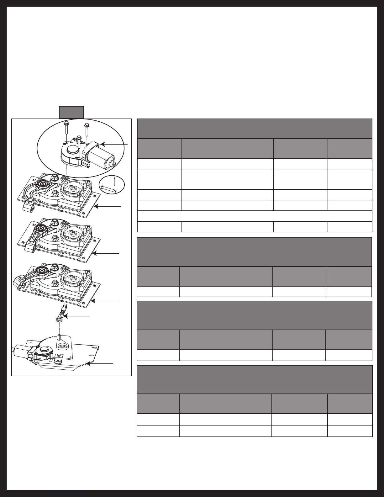
Van Steps
If the van step is equipped with a splash cover, remove the cover to access motor assembly and control unit.
If step is locked in retracted (UP) position and the plastic cover can not be removed, disassemble the step
tread to access the plastic cover. To disassemble the tread, remove the eight ¼" - 20 x 1” long hex head
bolts in tread side rails (connects tread and sliding blocks to side rail). This allows the tread to drop out of
the way and the plastic cover to be accessible. Reassemble the tread after removing the cover. Reinstall the
cover after testing procedures and any necessary repairs are complete. Fully extend the step to reinstall the
cover. Make sure that the 4-way connector exits the notch in the plastic cover when reassembling.
Step control wiring is only to be used for step and step light (provided with the step) functions. Do not splice
or tap into any of the step wiring. Failure to heed this warning may result in failure of step control, which
may result in loss of step function or fire in the step control.