L2 BPA10T30W100 User manual

BPA10T30W100 Broadband System User Manual
E-Mail: sales@l2microwave.com
www.l2microwave.com
- 1 -
User Manual
- BPA10T30W100 -
Please read this manual before using the equipment.
And keep this manual with the equipment.

BPA10T30W100 Broadband System User Manual
E-Mail: sales@l2microwave.com
www.l2microwave.com
- 2 -
- Contents -
1. GENERAL............................................................................................................................... 4
1.1. Information about this User Manual ..................................................................................................................... 4
1.2. Purpose of Operation............................................................................................................................................ 4
1.3. Responsibility of the Operator .............................................................................................................................. 5
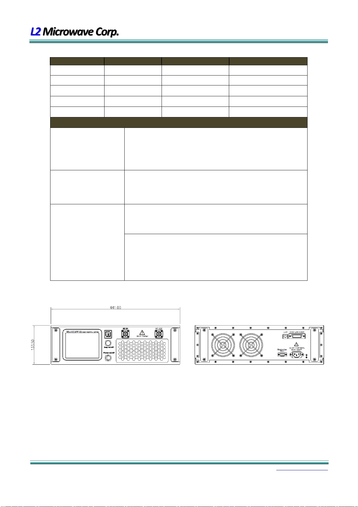
1.4. Specifications........................................................................................................................................................ 6
2. SAFETY..................................................................................................................................8
2.1. Basic Safety Instructions ....................................................................................................................................... 8
2.2. Product-specific Safety Instructions ...................................................................................................................... 8
2.2.1. Safety Instruction for Amplifier System and Equipment.......................................................................................8
2.2.2. Hazards from Supply Voltage................................................................................................................................8
2.2.3. Power Supply ........................................................................................................................................................8
2.2.4. High energy electrical circuits...............................................................................................................................9
2.2.5. Hazards from high-frequency currents .................................................................................................................9
2.2.6. Hazards from RF Radiation ...................................................................................................................................9
2.2.7. Occupational safety from RF shielding .................................................................................................................9
2.2.8. Flue gases..............................................................................................................................................................9
2.2.9. Rules for amplifier services.................................................................................................................................10
2.3. Operator (Personnel/User) ................................................................................................................................. 10
2.4. Safety Devices..................................................................................................................................................... 10
2.4.1. Protective Covers ................................................................................................................................................10
2.4.2. Instructions for Protection against Electrostatic Discharge (ESD).......................................................................10
3. INSTALLATION ..................................................................................................................... 11
3.1. Installation Position Selection............................................................................................................................. 11
3.2. Transport and Moving......................................................................................................................................... 11
3.3. Power Supply...................................................................................................................................................... 11
3.4. Load Condition for System Output ...................................................................................................................... 11
4. OPERATION METHOD .......................................................................................................... 13
4.1. Equipment operating sequence. ......................................................................................................................... 13
4.2. Alarm and Description for Status LCD ................................................................................................................. 14
4.2.1. Initial Screen Status ............................................................................................................................................14
4.3. Remote Control................................................................................................................................................... 18
4.3.1. GPIB Control .......................................................................................................................................................18

BPA10T30W100 Broadband System User Manual
E-Mail: sales@l2microwave.com
www.l2microwave.com
- 4 -
1.General
1.1. Information about this User Manual
This user manual is a part of the BPA10T30W100 broadband amplifier system of L2 Microwave Corporation
and describes the design, function, operation and components of the broadband amplifier system. The terms
of the model BPA10T30W100, broadband amplifier, and broadband amplifier system are used as synonyms in
this user manual.
Contents
The user manual for the broadband amplifier system describes all the required activities for the installation,
operation, and diagnostic procedures of the broadband amplifier.
Safety
All skilled personnel working with the broadband amplifier system or its components must read the relevant
information and follow the safety instructions outlined in the user manual. The broadband amplifier must be
used according to the operational purposes and regulations, and all operations associated with the broadband
amplifier or individual components must be performed by skilled personnel. Any additional skills and
qualifications are referenced in the appropriate sections in the manual.
Symbol
This triangle symbol means danger. Caution should be exercised if you do not follow this manual
correctly or do not comply with it, this may damage the equipment. Do not proceed to the next step until you
fully understand and meet the indicated conditions.
This triangle symbol means caution. This equipment is a Class 1 safety ground product (provided the
protective earth included in the power cord). Only the line power plug should be inserted into the outlet
provided with the protective earthing contact. Damage to the protective conductor inside or outside may
expose the product to hazards and should not intentionally damage the protective conductor.
If you have specific instructions, they are numbered and contain additional information for easier handling
and processing of the broadband amplifier system.
1.2. Purpose of Operation
•The BPA10T30W100 is used to amplify electrical input signals with frequencies and powers that meet the
limits specified in the technical specifications.
•All interfaces are used to connect external devices, the inputs and outputs of which correspond to the
requirements of the respective interface specifications provided in the technical specifications, please refer
to the data sheet of the BPA10T30W100.
•The BPA10T30W100 should only be used under the environmental conditions specified in the technical
specifications.
This type of system should only be operated by qualified personnel and require a high level of accountability
to ensure proper operation, understanding of technical complexity, and the ability to safely cope with potential
risks. Examples of applications that can be used include.

BPA10T30W100 Broadband System User Manual
E-Mail: sales@l2microwave.com
www.l2microwave.com
- 5 -
•RF amplifiers that produce high field strength through radiation antennas for EMC measurements, materials,
and device testing in fully shielded chambers.
•RF amplifier for energy generation for particle acceleration.
•RF amplifiers for feeding magnetic field coils.
1.3. Responsibility of the Operator
Operator
The operator is the company/institution that operates the instrument for its own commercial or scientific
purposes or makes it available for use/usage to third parties and holds the legal product liability for protecting
the user, personnel or third party during operation.
Obligations of the operator
The broadband amplifier is used in commercial applications, and operators of the broadband amplifier are
subject to legal obligations for industrial safety. In addition to the safety instruction in this manual, the
regulations for safety, accident prevention, hygiene and environmental protection must be observed. In
particular, the following applies.
•The operator shall be familiar with their workplace safety regulations and risk assessment to identify the risks
that may arise from the specific operating conditions of the site where the broadband amplifier is used.
Appropriate operating instruction for operating the broadband amplifier should also be prepared to prevent
hazards.
•The operator shall periodically check that operational instructions created in accordance with the rules
during the entire operating time of the broadband amplifier meet current regulatory requirements. The
operator shall modify the operating instructions when any changes are made.
The operator shall also be responsible for ensuring that the broadband amplifier and all systems connected
to the instrument are always in perfect working order. Therefore, the following applies.
•The operator shall be obligated to have all safety devices that are connected to the system checked regularly
for proper function and completeness.
•The operator of broadband amplifier system is responsible for ensuring the safe working conditions of the
personnel.
•The operator must comply with the maintenance period described in this manual.
When an operator enters or exits a room where high field strengths occur, the RF interlock system and
personal RF warning devices must be used to protect against the risk of radiated RF power.

BPA10T30W100 Broadband System User Manual
E-Mail: sales@l2microwave.com
www.l2microwave.com
- 6 -
1.4. Specifications
ELECTRICAL SPECIFICATIONS @ 220VAC, 25C, 50
Parameter
Symbol
Min
Typ
Max
Unit
Operating Frequency
BW
1000
3000
MHz
Output Power @ PSAT, CW
PSAT
100
140
Watt
Power Gain @ Psat
GS
53
dB
Input Power for Rated PSAT
PIN
0
dBm
Gain Flatness @ Rated PSAT
G
±1.5
dB
Input Return Loss
S11
-10
dB
In/Out Impedance
Z
50
ohm
Third Order Intercept Point
2-Tones @ 41dBm/Tone, = 100 kHz
IP3
+55
dBm
Harmonics @ Pout =100W
2nd / 3rd
-20
dBc
Spurious Signals
Spur
-70
-60
dBc
Power consumption @ PSAT
VAC
1000
1600
Watt
MECHANICAL SPECIFICATIONS
Parameter
Value
Units
Note
Dimensions ( H x W x D)
133.5 x 441 x 522.2
mm
3U
Weight
Typ. 25
kg
Max
RF Connectors Input/Output
N type, Female
Front
Primary Power
88~264 VAC, 50/60Hz
3 pin Single phase
Cooling
Air cooling
Self-contained fans & Heat sink
ENVIRONMENTAL CHARACTERISTICS (Design to Meet)
Parameter
Symbol
Min
Typ
Max
Unit
Operating Case Temperature
Tc
-20
+60
°C
Storage Temperature
Tstg
-40
+85
°C
Relative humidity (non-condensing)
RH
95
%
Altitude ( MIL-STD-810F Method 500.4)
ALT
30,000
Feet
Vibration/Shock
MIL-STD-810F-Method 514.5/516.5-Proc I
VI/SHI
Airborne

BPA10T30W100 Broadband System User Manual
E-Mail: sales@l2microwave.com
www.l2microwave.com
- 7 -
OPTIONS
Auto Gain Control
Remote control
Display
Option #
X
X
2 color LED
Option #000
O
X
2 color LED
Option #100
O
X
Touch LCD
Option #101
O
O
2 color LED
Option #110
O
O
Touch LCD
Option #111
Description
▷Auto Gain Control
-. Control function to improve linearity
; Monitoring the input and output levels of the system in real time and
adjust the amount of internal attenuation for maintain a constant gain.
; The dynamic range of the AGC function guarantees more than 20dB
of rated power.
▷Remote control
-. Function to operate amp system through external control unit
; Communication protocol by IEEE-488 (GPIB), Ethernet (RJ-45), USB 2.0
; Amplifier on/off. ID return.
; Information transfer on amplifier steady and fault conditions.
▷Display
-. 2 color LED Indication
; Abnormal Alarm ( Temperature / Current / Power )
; If an abnormal condition occurs in the amplifier, the amplifier will
automatically shut down and display a notification with an LED.
-. Touch LCD Display
; LCD display of amplifier status. The status of the amplifier is displayed
in real time, and when an error occurs, a notification function and an
automatic shutdown are performed. It includes an amplifier check
function and a connection with an external control unit.
OUTLINE DRAWING

BPA10T30W100 Broadband System User Manual
E-Mail: sales@l2microwave.com
www.l2microwave.com
- 8 -
2.Safety
2.1. Basic Safety Instructions
Chapter 1 "General" of this manual contains "Basic Safety Instructions" that apply to all products produced
and supplied by L2 Microwave. The BPA10T30W100 broadband amplifier system and its ancillary equipment
must only be operated by qualified technicians.
Compliance with all legal provisions is a prerequisite for operating the broadband amplifier. The operator or
agent authorized by the operator is responsible for complying with these instructions. And training for
authorized representatives must meet local requirements.
2.2. Product-specific Safety Instructions
2.2.1. Safety Instruction for Amplifier System and Equipment
•Only trained personnel can perform electrical installation and connection tasks.
•When installing an operating area and installing or operating electrical equipment, always comply with the
relevant national and international safety rules and regulations.
•When installing an amplifier rack, it is important to comply with national special accident prevention.
2.2.2. Hazards from Supply Voltage
Risk of fatal injury from electrical voltage
•When working with voltages that constitute a shock hazard, appropriate measures must be taken to prevent
exposure to danger.
2.2.3. Power Supply
Risk of property damage
Operation without protection against overloads and short circuits can lead to damage to the instrument, fire,
or arcing.
•Before connecting the power supply, it is important to ensure that the system or the power supply
specifications applied to the equipment comply with the general specifications of the local power supply
network.
•The power supply device must be protected at all times through a fuse or an earth leakage power breaker to
prevent overload and short circuit.
•If the equipment is permanently connected to the power supply without a power plug, install a device that
will power off the power supply circuit at all poles.

BPA10T30W100 Broadband System User Manual
E-Mail: sales@l2microwave.com
www.l2microwave.com
- 9 -
2.2.4. High energy electrical circuits
Electrical circuits carrying high amounts of energy pose a risk of injury.
This equipment has a low voltage circuit that can be supplied from an extremely low impedance voltage
source (e.g. amplifier operating voltage). These circuits carry dangerously high levels of energy.
These electrical circuits are considered circuits with hazardous contact voltages. Therefore, the user should
always be careful about electrical contacts.
2.2.5. Hazards from high-frequency currents
Burn hazard from arcing
All of the power-conducting RF plug connectors and RF modules require attention to contact current. Arcing
may occur if high-frequency cables are plugged in or unplugged while the amplifier is in operation. This can
cause burns and eye injuries. At open high-frequency interfaces with active gain there is a burn hazard in the
high-frequency range and risk of electric shock in the low-frequency range.
•Operate the amplifier system after firmly fixing the antenna or load.
•Never disconnect the high frequency cable while the amplifier system is in operation.
•Never open the amplifier system while it is in operation.
•Never operate the amplifier system if the RF cables are exposed.
2.2.6. Hazards from RF Radiation
Risk of injury from high-frequency electromagnetic radiation
High frequency electromagnetic radiation during operation of the broadband amplifier can be generated in
the beam portion of the antenna with a specific absorption rate that is higher than the human exposure limits.
Prolonged exposure may cause eye damage and metabolic disorders.
Operate the amplifier system only in such a way that the beam area of the antenna is located in a shielded,
access-restricted room or area.
2.2.7. Occupational safety from RF shielding
The BPA10T30W100 broadband amplifier system is shielded from all RF cables, shielding covers and case
components to ensure that they are not exposed to RF radiation even if they are close together for extended
periods of time. This industrial safety clause is based on Korean legislation.
2.2.8. Flue gases
Severe health damage may be caused by flue gas formation.
In general, any flue gases produced by burning of casing parts, cables, insulation materials, batteries, etc.
can result in serious harm to a person's health.

BPA10T30W100 Broadband System User Manual
E-Mail: sales@l2microwave.com
www.l2microwave.com
- 10 -
•Use personal protective equipment in the event of smoke formation. Use breathing protection in the danger
zone that is independent of the ambient air.
2.2.9. Rules for amplifier services
Do not operate the amplifier system (equipment) unless the case is closed.
Risks when reconnecting the power supply
Do not reconnect the power supply until the amplifier is fully installed. Failure to observe this may result in
electric shock or RF radiation.
•Ensure that all case components are securely installed.
•Ensure that all cables and grounding lines are properly connected.
2.3. Operator (Personnel/User)
Risk of injury from insufficient qualification of personnel
All work (operation, maintenance, troubleshooting, repair, etc.) should be performed only by qualified
personnel. Failure to do so may result in serious injury or property damage.
2.4. Safety Devices
2.4.1. Protective Covers
Risk of injury due to removed protective covers
This symbol indicates a protective cover for electrical circuits at risk due to large amounts of energy,
RF current or supply voltage. The protective cover prevents unintentional contact with these electrical circuits.
•Pay attention to the cover marked with this symbol.
•Do not remove the protective cover with this symbol.
•Any work that requires accessing the inside of the system may be carried out by the manufacturer's service
personnel only.
2.4.2. Instructions for Protection against Electrostatic Discharge (ESD)
Risk of damage to electronic components
To avoid damage to electronic components, all work on the equipment and components must be performed
in a location protected against electrostatic discharge (ESD). The following items can be used individually or in
combination to protect against electrostatic discharge.
•Protective armband with grounding cable
•Wearing antistatic shoes and antistatic clothes

BPA10T30W100 Broadband System User Manual
E-Mail: sales@l2microwave.com
www.l2microwave.com
- 11 -
3.Installation
This chapter describes the installation of the BPA10T30W100 broadband amplifier and the requirements for
the peripheral infrastructure.
3.1. Installation Position Selection
RF Radiation
The BPA10T30W100 is a broadband amplifier that generates electromagnetic waves and may affect other
sensitive equipment; therefore, should only be operated in an industrial environment.
Installation position
This equipment uses air circulation cooling method using FAN to release heat by high power operation.
Therefore, we recommend installation in a spacious space with no dust or other contaminants.
Others
The operator of the BPA10T30W100 should not be disturbed during operation of the broadband amplifier
system. The recommended power of the BPA10T30W100 is 1.6kW or more. We recommend installation only in
places where breakers and electric power facilities are 1.6kW or more.
3.2. Transport and Moving
Avoid product damage (damage) caused by improper transportation. Improper transport can cause
the product to fall or fall, causing serious damage to the equipment.
• Broadband amplifiers must be installed with L2 Microwave or qualified personnel, although they may vary
depending on the equipment.
• Do not disassemble or move the installed broadband amplifier arbitrarily.
• When moving with forklifts and other lifting machines, the broadband amplifier should not tilt to one side
and move carefully to avoid affecting the internal parts. If it is tilted to one side, it may fall over, causing
internal or external damage to the rack.
3.3. Power Supply
The BPA10T30W100 wideband amplifier system operates with the following AC voltages.
-Acceptance input voltage : AC 220V single phase
-Maximum power consumption : 1.6 kW
-Power frequency : 47 Hz ~ 63 Hz
3.4. Load Condition for System Output
In general, the most defects in broadband amplifier operation are caused by high VSWR of load. Be sure to
check the conditions for the amplifier load as shown below.

BPA10T30W100 Broadband System User Manual
E-Mail: sales@l2microwave.com
www.l2microwave.com
- 12 -
• Check for deficiency between amplifier output and load
-. It is recommended that VSWR of RF cable applied between amplifier output and load is less than 1.5: 1.
-. Check the VSWR of the load before connecting the amplifier and load.
Check the VSWR of the antenna connected to the output of the amplifier during the radiation experiment.
The minimum required VSWR for the antenna should be used under 1.5 : 1.
If the operator wants to use it under high VSWR conditions, the amplifier's output can be used at a lower level.
The following table shows VSWR condition of Load vs. Output Power of BPA10T30W100.
Output power
VSWR Condition of Load
100W
Under 2.0:1
63W
Under 2.2:1
40W
Under 3.0:1

BPA10T30W100 Broadband System User Manual
E-Mail: sales@l2microwave.com
www.l2microwave.com
- 13 -
4.Operation method
This chapter describes the operation and condition of the amplifier.
The AMP ON / OFF button on the front panel operates the amplifier and checks the condition of the amplifier.
If an error occurs in the amplifier, the Alarm LED on the front panel will change to RED and the amplifier will go off.
To reactivate the amplifier, remove the cause of the alarm and operate by pressing the AMP ON / OFF button again.
4.1. Equipment operating sequence.
To control the amplifier, follow by below sequence for system operation.
①Plug in rear power switch ON.
-Use power cable that can supply more than 1.6kW.
-Connect to ground wire between amplifier and installation site using M3 Nut.
-Turn on the power breaker.
②Check the status of the front panel of amplifier.
(Refer to “4.2 Alarm and Description for Status LCD”)
③Press the “AMP ON/OFF” push button. From OFF mode to ON mode.
④Input the RF input signal.
-Slowly increase the input value from the -20 dBm input to the target output.
The system is off in reverse order.

BPA10T30W100 Broadband System User Manual
E-Mail: sales@l2microwave.com
www.l2microwave.com
- 14 -
4.2. Alarm and Description for Status LCD
This Chapter describes the front status of LCD.
4.2.1. Initial Screen Status
•Description of Display part
User can change the FWD and RVS values of the RF Power Display by selecting dBm or Watt of the
display.
①If you change the value of the cell of Display to dBm, it will be displayed as follows.
②If you change the value of the cell of Display to Watt, it will be displayed as follows.

BPA10T30W100 Broadband System User Manual
E-Mail: sales@l2microwave.com
www.l2microwave.com
- 15 -
•Description of AMP Status part
- This part displays the status of AMP inside the shelf.
- You can change the status by pushing the button of Amp ON / OFF.
Amp OFF normally.
Amp OFF when alarm is occurred.
Amp works normally.
•Description of Frequency part
①This part displays the status of Frequency of the shelf.
-You can change the value of Frequency by touching the button of Set.
And the below screen is displayed.
-How to use the screen of change about Frequency
-> End : Button to exit Frequency keypad.
-> Save : Button to save written Frequency.
-> Clear : Button to delete written Frequency.
-> 0 ~ 9 : Number button.

BPA10T30W100 Broadband System User Manual
E-Mail: sales@l2microwave.com
www.l2microwave.com
- 16 -
•Description of RF Power Display part
- Display RF Power status and change the % of color by output.
(Rated output is 100%.)
- Display FWD (Forward Detect) Power value.
- Display RVS (Reverse Detect) Power value.
•Description of Status Value part
①Status Value : Display status of shelf.
- AMP Temp : Display self temperature status.
(Don't be displayed when PSU status is OFF.)
- Supply Power : Display the Supply Power used by the shelf.
•Description of Alarm light part
①Status of shelf is normal.
- The status of shelf is all normal. You can use this shelf.
②Temp Alarm of is occurred on shelf.
- It is occurred if the temperature of shelf is above 70℃.
- If the Temp alarm is occurred, cool down the temperature and push the Alarm Reset
button.
③VSWR Alarm is occurred on shelf.

BPA10T30W100 Broadband System User Manual
E-Mail: sales@l2microwave.com
www.l2microwave.com
- 17 -
- It is occurred if FWD value is higher than RVS value.
- Check the equipment connected to the RF Out Pin such as cables, antennas
and so on.
-> You have to use the shelf after checking RF Out Pin.
Otherwise, the product may be malfunction.
④Current Alarm is occurred on shelf.
- Alarm is occurred when the AMP inside the shelf is over current or standby current.
- Over current may be occurred if you're using more than the rated power of the shelf.
-> It is not recommended to use more than the rated output.
-> If the Current Alarm is occurred, turn off the RF input and touch the Alarm Reset
button.
- Standby current may be occurred if the internal AMP is abnormal.
-> How to check the standby current
1) Turn off the RF Input.
2) Push the Alarm Reset button.
3) Push the Amp On/Off button
4) If it occurred even after inspection, please contact the supplier.
⑤RF Power Alarm is occurred on shelf.
- It is occurred if FWD value is higher than 125W. (Rated Output is 100W.)
-> It is not recommended to use more than the rated output.
-> If the RF Power Alarm is occurred, turn off the RF input and touch the
Alarm Reset button.

BPA10T30W100 Broadband System User Manual
E-Mail: sales@l2microwave.com
www.l2microwave.com
- 18 -
4.3. Remote Control
4.3.1. GPIB Control
•Description of GPIB part
①Change or display the address of GPIB.
- ▲: The GPIB address value is increased.
- ▼: The GPIB address value is decreased.
- Save : You can save the GPIB address value by touching the button.
•GPIB command
"IDN?"
-
Check the unique information of AMP
Response
Manufacturer, model, serial number, and version
"AMP?"
-
Check the On/Off status of AMP
Response
"AMP ON" or "AMP OFF"
"AMP ON"
Control
Turn on AMP
"AMP OFF"
Control
Turn off AMP
"HZ?"
-
Check the amp’s frequency information
Response
"Hz nnnnMHz" Records nnnn = 1000 ~ 6000
"HZ nnnn"
-
Record the amp’s frequency information
Control
"HZ nnnn" Records nnnn = 1000 ~ 6000 ( change frequency)

BPA10T30W100 Broadband System User Manual
E-Mail: sales@l2microwave.com
www.l2microwave.com
- 19 -
4.3.2. LAN Control
• IP Address Set
To connect to the LAN, User has to check the user’s network IP Address and be entered network IP address into
the amplifier system.
In order to input IP Address to the amplifier system, it must be entered on the LCD window and the LCD GUI
program at the same time.
The procedure to enter is as follows.
1. Connect amplifier system and user’s network with LAN line.
2. Click the LAN box on the LCD of Amplifier system and activate it.
→
3. In order to activate the “Control Panel folder” of window, click the control button on the LAN box.
4. To create the following folder, click “Control Panel folder”.
<Activate Control Panel folder of window>
- Click the 3rd button, The following folder is created.
- Click the 3rd button (GMAC).
The following “‘Remote-NDIS Host’ Settings” is created.
Record user’s network IP Address in the activated “’Remote_NDIS Host’ Settings” folder.
It is important to note that the 4th value is a number different from the user's network IP Address to avoid collision.

BPA10T30W100 Broadband System User Manual
E-Mail: sales@l2microwave.com
www.l2microwave.com
- 20 -
When you are done, close all folders.
5. Close the “Control Panel folder” of window and record the IP Address entered in the “'Remote_NDIS Host'
Settings” folder in the IP address of the LAN box.
Table of contents
Popular Modem manuals by other brands

Eminent
Eminent EM4218 manual

Alcatel-Lucent Enterprise
Alcatel-Lucent Enterprise OmniAccess Stellar AP1320 Series installation guide

Adp
Adp ATS 700 installation guide

Paradyne
Paradyne COMSPHERE 3920PLUS Series Installation and operation manual

Zoom
Zoom 3095F quick start

Campbell
Campbell Sierra Wireless RavenXTV instruction manual