GENERAL MANUAL
VOUGEOT - VOLNAY
Page 4 of 43
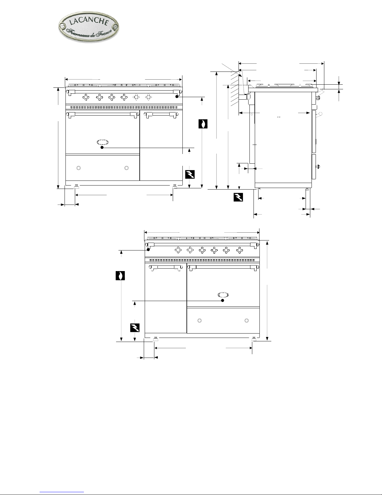
Layout :
5-burner cook’s stove, oven and storage cupboard GN 1/1 (Figure 1 & 3).
Description :
Enamelled steel or stainless body panels AISI 430. Pressing cooking surface (stainless steel AISI 304) (Figure 4 and 5). 5-
burners of different size and power individually controlled by a safety valve. Electrical ignition.
TRADITION” model equipped with a 385 x 510 mm (15 5/32’’ x 20 5/64’’) heating plate (Figure 6).
Gas oven :
Enamelled sheet metal. Dimensions W x H x D : 530 mm (20.8’’) x 305 mm (12’’) x 460 mm (18.1’’). 4 shelf level with
62 mm spacing, 62 liters / 2.18 ft3. Heating provided by thermostatically controlled burner, thermocouple safety cut-outs.
Electrical ignition.
Power supply : 120 / 240 VAC 60Hz.
Static electric oven (option) :
Same dimensions as gas oven.
Thermostatically controlled roof and base heating elements, safety cut-out by safety thermostat.
Rating : 3400 W – Power supply : 240 Volts 60Hz.
Ventilated electric oven (option)
Heating provided by two circular heating elements each surrounding a reaction-type fan. Dimensions W x H x D : 530 mm
(20.8’’) x 305 mm (12’’) x 405 mm (15.9’’). This can optionally be fitted with an electric.
Thermostatically controlled heating elements, safety cut-out by safety thermostat.
Rating : 3700 W – Power supply : 240 Volts 60Hz.
Plate warmer cabinet (option)
Plate warmer-insulated stainless internal lining (AISI 304). Heating provided by 950 W heating element underneath base.
Controlled by thermostat selector switch, 30 to 110 °C. Capacity : 72 plates, Ø 240 mm (9.5’’). Dimensions W x H x D :
325 mm (12.8’’) x 490 mm (19.3’’) x 530 mm (20.8’’). 5 shelf level with 68 mm (2.8’’).
Rating : 1030 W – Power supply : 240 Volts 60Hz
Accessories
One drip tray, one shelf, one pastry tray per oven. General-purpose cabinet : 1 shelf. Plate warmer cabinet : 2 shelves.
Shipment-Packaging
Unpack and check the appliance is in good condition. In case damage, note any reservations on the delivery note and
confirm them within 48 hours by registered letter with confirmation of delivery to the carrier.
Appliance Width Depth Height mm Weight Gross/Net
LG 1051 G 1130 mm / 44.5’’ 760 mm / 29.9’’ 1050 mm / 41.3’’ 120 kg /108 kg – 267 / 240