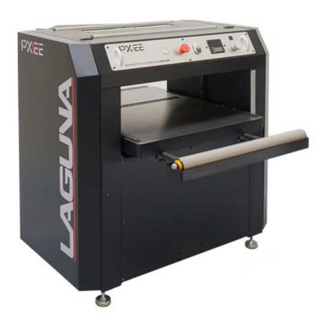
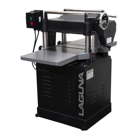
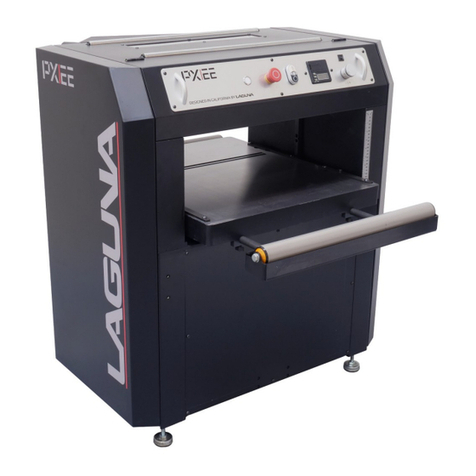
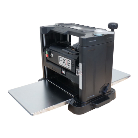
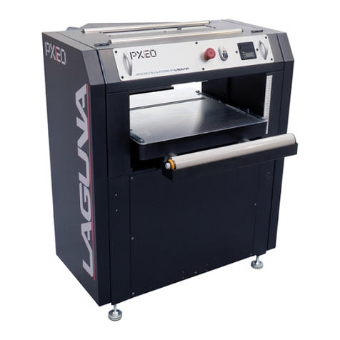
laguna MPLAN25-15-3-0130 User manual

0
Operating
Manual
Model
MPLAN25-15-3-0130 with CSA
MPLAN25-10-1-0130
WARNING
This tool should be connected to a
grounded metal permanent wiring system;
or to a system having an equipment-grounding
conductor
!
2072 Alton Parkway. Irvine, CA 92606
Ph: 800.234.1976 | www.lagunatools.com

1
WARNING
Read this manual completely and observe all warning labels on the machine.
Every attempt to provide a safe, reliable, easy-to-use piece of machinery. Safety, however, is
ultimately the responsibility of the individual machine operator. As with any piece of machinery,
the operator must exercise caution, patience, and common sense to safely run the machine.
Before operating this product, become familiar with the safety rules in the following sections.
Safty Rule
1. KEEP GUARDS IN PLACE and in working order.
2. REMOVE ADJUSTING KEYS AND WRENCHES. Form habit of checking to see
that keys and adjusting wrenches are removed from tool before turning it on.
3. KEEP WORK AREA CLEAN. Cluttered areas and benches invite accidents.
4. DON'T USE IN DANGEROUS ENVIRONMENT. Don't use power tools in damp
or wet locations, or expose them to rain. Keep work area well lighted.
5. KEEP CHILDREN AWAY. All visitors should be kept safe distance from work
area.
6. MAKE WORKSHOP KID PROOF with padlocks, master switches, or by
removing starter keys.
7. DON'T FORCE TOOL. It will do the job better and safer at the rate for which it
was designed.
8. USE RIGHT TOOL. Don't force tool or attachment to do a job for which it was not
designed.
9. WEAR PROPER APPAREL Do not wear loose clothing, gloves, neckties, rings,
bracelets, or other jewelry which may get caught in moving parts. Nonslip
footwear is recommended. Wear protective hair covering to contain long hair.
10.ALWAYS USE SAFETY GLASSES. Also use face or dust mask if cutting
operation is dusty. Everyday eyeglasses only have impact resistant lenses, they
are NOT safety glasses.
11.SECURE WORK. Use clamps or a vise to hold work when practical. It's safer
than using your hand and it frees both hands to operate tool.
12.DON'T OVERREACH. Keep proper footing and balance at all times.
13.MAINTAIN TOOLS WITH CARE. Keep tools sharp and clean for best and safest
performance. Follow instructions for lubricating and changing accessories.

2
14.DISCONNECT TOOLS before servicing; when changing accessories, such as
blades, bits, cutters, and the like.
15.REDUCE THE RISK OF UNINTENTIONAL STATING. Make sure switch is in off
position before plugging in.
16.USE RECOMMENDED ACCESSORIES. Consult the owner's manual for
recommended accessories. The use of improper accessories may cause risk of
injury to persons.
17.NEVER STAND ON TOOL Serious injury could occur if the tool is tipped or if the
cutting tool is unintentionally contacted.
18.CHECK DAMAGED PARTS. Before further use of the too., a guard or other part
that is damaged should be carefully checked to determine that it will operate
properly and perform its intended function - check for alignment of moving parts,
binding of moving parts, breakage of parts, mounting, and any other conditions
that may affect its operation. A guard or other part that is damaged should be
properly repaired or replaced.
19. DIRECTION OF FEED. Feed work into a blade or cutter against the direction of
rotation of the blade or cutter only.
20. NEVER LEAVE TOOL RUNNING UNATTENDED. TURN POWER OFF. Don't
leave tool until it comes to a complete stop.
21. Installation work and electrical wiring must be done by qualified electrician in
accordance with all applicable codes and standards.
Familiarize yourself with the following safety notices used in this manual:
CAUTION: (This means that if precautions are not heeded, it may result in
minor or moderate injury and/or possible machine damage)
WARNING: (This means that if precautions are not heeded, it could result in
serious injury or possibly even death).

3
Table of Contents Page
Safty Rule ................................................................................................................1
Uncrating the Machine.............................................................................................4
Machine Preparation and Setup ..............................................................................4
Dust Chute Assembly ..............................................................................................5
Table Roller Handle Assembly................................................................................. 5
Control Panel........................................................................................................... 5
Operation Panel....................................................................................................... 6
Raising and Lowering Table .................................................................................. 18
Adjusting Thickness Scale..................................................................................... 18
Table Roller Adjustment ........................................................................................ 18
Changing Feed Rate.............................................................................................. 18
Table Stop ............................................................................................................. 18
Opening Hood........................................................................................................ 18
ShearTec II CUTTERHEAD.................................................................................. 19
Setup of Feed Rollers, Chip Breaker and Pressure Bar ................................... 20
Anti-Kickback Fingers ............................................................................................ 21
Adjustment of In-Feed Roller ................................................................................. 21
Adjustment of Chipbreaker .................................................................................... 21
Adjustment of Pressure Bar................................................................................... 22
Adjustment of Out-feed Rollers.............................................................................. 22
Adjusting Table Gibs.............................................................................................. 22
V-Belt Adjustment .................................................................................................. 23
Adjusting Table Rollers.......................................................................................... 23
Maintenance .......................................................................................................... 24
Troubleshooting ..................................................................................................... 25
Wiring Diagrams
.................................................................................................... 26
PARTS DIAGRAMS............................................................................................... 28
PARTS LIST .......................................................................................................... 34
4
Uncrating the Machine
Retain all packaging materials in case it
becomes necessary to ship the machine to
another site.
Machine Preparation and Setup
WARNING!
The equipment used to lift this machine must
have a rated capacity at, or above the weight
of the planer. Failure to comply may cause
serious injury!
The planer can be lifted from over head
using slings and the four lifting hooks A.
The planer must be positioned on a
smooth, level surface. Install the leveling
pads B under the four corners of the
planer.
Clean all rust protected surfaces with a
commercial solvent. Do not use acetone,
gasoline, lacquer thinneror any type of
flammable solvent, or a cleaner that may
damage paint. Cover cleaned surfaces
with WD-40 or a 20W machine oil.
Place a level on the table of planer and
adjust leveling bolts C until the machine is
resting level. Tighten the hex nuts D
against the base of the planer to keep the
leveling bolts from turning (Fig. 1)

5
Dust Chute Assembly
Mount the dust chute to the planer hood
with eight M6x10 hex head screws B.
Make sure the dust collection system has
sufficient capacity and suction for your
planer. Always turn on the dust
collection system before starting the planer.
(Fig. 2)
Table Roller Handle Assembly
Thread the handle C (Fig. 3) into the hub.
Control Panel
In Fig. 3
D: Emergency Stop Button: Stops all
functions of machine, but the planer still
has power. To reset rotate switch
clockwise until the button pops out.
E: Main Motor: Starts rotation of
Cutterhead. Will not work if the
“Emergency Stop”switch is engaged, or
hood is open.
F: Digital Thickness Controls: Displays
and controls table position, units, etc..
G: Table Up: Raises the table.
Note: Table will contact the upper limit
switch at about 5/8”. You can continue
to raise manually by using the
handwheel.
H: Table Down: Lowers the table.
Note: Table will contact the lower limit
switch at about 8-5/8”. You can
continue to lower manually by using the
handwheel.
Note: Do not feed material through the
planer while the table is raising or
lowering.

6
Operation Panel
Function:
1.
One
or
two
speed
positioning
7.
Resolution:
0.1mm/
0.05mm/
0.01mm
2.
Manual
/
Single
mode
8.
Correct
zero
point
3.
10
sets
single
program
9.
Display:
RPM
speed
4.
10
sets
tool
offsets
10.
Protection
for
tool
/
motor
fault
5.
Quick
program
/
Fine
Adjustment
11.
Battery
life
2.5
year
6.
Inch
/
mm
conversion
12.
Self-diagnose

7
Manual Mode
Description:
To
move
the
machine
table
by
pressing
M15
keyboard.
7
8
9
F
fast
forward
backward
fast
Example:
M15
displays
100.00mm,
to
move
the
machine
table:
※
Note:
Be
sure
in
“
manual
”
mode.
(LED
lamp
of
“manual
/
Single”
key
is
blinking)
The
upper
window
shows
“HAnd”
mode.
=
H
A
n
d
106.80
Press
to
move
machine
table
7
(fast).
forward
H
A
n
d
=
Press
F
to
move
machine
table
backward
(fast).
96.80
Note:
Press
8
or
9
for
forward/
backward/
lower
speed
(depends
on
machine
and
wiring).
Single Mode
Description:
M15
can
execute
auto
positioning.
Example:
M15
current
value
is
100.00mm,
to
reach
200mm
(setting
target
value).
Step1.
Select
single
mode
LED
lamp
is
off.
100.00
100.00
200.00
Step2.
Press
PROG
,
blinking,
enter
new
target
value
2
0
0
100.00
LED
lamp
is
off,
complete.
※
Note:
During
positioning,
press
STOP
to
stop;
to
re-start,
press
PROG
and

8
Pre-Set
Program
(10 sets)
Description:
Pre-set
program
10
sets,
enter
program
#
0~9
to
execute.
Example:
Program
1=10mm,
Program
2=20.00mm.
ProG
Step1.
Press
F
5
5
select
enter
a
key
(0-9,
total
of
10sets).
※
Note:
Be
sure
in
manual
mode.
ProG
1
Step2.
(Enter
program
1=10mm),
press
1
more
press
1
0
.
10
ProG
Step3.
Target
value
display:
ProG
_
at
present,
enter
program
2=20.00mm,
press
to
exit.
Program Open and Lock (10 sets)
Description:
Don’t
needs
pre-set
program,
to
start
or
close.
Example:
Program
1=10.00mm
for
0
,
program
2=
20.00mm
for
1
,
2
~
9
other
a
key,
don’t
setting
pre-set
program,
to
stop
follow
steps
as
below:
ProG
Step1.
Press
F
55
target
value
display:
ProG_
.
※
Note:
Be
sure
in
single
mode.
ProG
2
Step2.
Press
2
current
value
display:_
_
_
_
_
_,
2
closed,
20.00
frame
display,
2
started.
ProG
Step3.
Press
STOP
to
close
2
※
Note:
To
close
other
keys,
follow
the
step
2,
3.

9
Fast
Program
Description:
To
facilitate
frequently
used
positions,
the
keys
0
to
9
have
associated
preset
target
values.
And
the
positioning
can
be
started
immediately.
Example:
Program
1=10.00mm,
program
2=20.00mm.
Execute
program
2
as
below:
100.00
100.00
Step1.
Select
singe
mode
LED
lamp
off.
20.00
Step2.
Press
2
target
value
display:
20.00mm
START
LED blinking, to waitting start.
100.00
※
Note:
Execute
program1
press#1.
Fine
Adjustment
Description:
Increase
and
decrease
to
reach
fine
adjustment.
Example:
M15
target
value
display100.78mm,
increase/
decrease
target
value0.25mm,
setting
steps
as
below:
0.00
Step1.
Increase
target
value:
press
display
0.00
LED
blinking,
+/-
100.00
decrease:
press
+/-
twice,
display-0.00
LED
blinking.
0.25
100.00
Step2.
Press
0
2
5
press
to
completed.
※
Note:
Target
value
display:
101.03mm,
current
value
display:100.78mm
for
target
value
increase
0.25mm.

10
Load
datum values
A.
Description:
To
load
current
value
according
to
working
piece.
Example:
M15
current
value
display100.00mm,
actual
size:
100.50mm,
follow
the
steps
as
below:
100.00
100.00
Step1.
Select
singe
mode
LED
lamp
off.
OriGin
Step
2.
Press
F
2
,
enter
new
100.00
value,
press
1
0
0
5
press
,
to
exit.
B.
How
to
show
the
new
set
value:
Step1.
Press
F
0
,
press
twice,
F
0
100.00
display
new
value.
Select
Counting Direction(+/-)
Description
:
To
select
the
counting
direction.
Example
:
M-15
current
value
display:
100.00mm,
sensor
forward
for
decrease
value
99.68mm,
but
hope
value
become
big,
value
increase
follow
the
steps
as
below:
100.00
99.68
Step1.
Press
back
single
mode,
LED
lamp
off.
Step
2.
Press
F
1
F
1
99.68
target
value
display
origin
parameter
value
“-dir”
(select
counting
direction
parameter).
-dir
Step
3.
Press
PROG
to
select
the
direction,
-dir
/
dir
(or"-dir"
for
left
or
"dir-
"
for
right.)
100.00
Step
4.
Press
to
complete,
and
exit.
99.68

11
Resolution
Description:
Select
resolution:
0.1mm/0.01mm/0.05mm.
Example:
M15
current
value
display100.0mm,
to
select
display:100.00mm
follow
the
steps
as
below:
100.0
100.0
F
90
100.0
Step
1.
Select
single
mode
LED
lamp
off.
Step
2.
Press
F
9
0
to
select
resolution.
rES
0.01
Step
3.
Press
8
/
9
(0.1
/
0.01
/
0.05)
100.00
100.00
Step
4.
Press
to
complete
and
exit.

12
Sensor Calibration
A
.
Description:
For
better
accuracy,
please
execute
calibration
immediately
after
installed
sensor
each
time.
Step
1.
Fix
sensor,
keep
1mm
gap
from
tape
(
RECOMMENDED
).
Gap
sensor-tape
Step
2.
Press
F
9
9
Target
value
display
GO
(Enter
parameter)
Step 3、Press and hold
8
GO
or
9
to
start.
※
Note
:
Moving
the
slider
at
low
speed,
Required
distance
around
120mm
(Moving
GO
)
Display:
GO
(Detecting)
Display:
GO
(Almost
complete)
When
completed
calibration,
LED
display
will
flash
and
-8
8
8
8
8
8
-8
8
8
8
8
8
show.
※
Note:
Please
reload
origin
datum
values
refer
to
page8.

13
B.
Troubleshooting
of
calibration:
GAP
Lo
GAP
Hi
GO
100
2.75
a.
Display:
GAP
LO
Possible
cause:
The
gap
is
too
narrow.
Excluding:
Please
enlarge
the
gap.
Press
and
follow
step
2
again.
b.
Display:
GAP
Hi
Possible
cause:
The
gap
is
too
big.
Excluding:
Please
narrows
the
gap
and
press
calibration
again.
c.
Display:
GO
or
GO
or
GO
Possible
cause:
The
gap
too
big
or
machine
surface
is
not
flat/smooth.
Excluding:
Adjust
gap
or
improve
the
machine
surface.
d.
d.
During
calibration
press
to
exit.
Set
Parameter
100.00
Step
1.
Select
single
mode
LED
lamp
off.
100.00
Step
2.
Press
F
select
enter
parameter
#,
example
F
2
100.00
OniGin
100.00
parameter
2,
press
2
Step
3.
Press
target
value
display
OriGin(Lond
parameter)
※
Note:
Refer
to
set
parameter
or
page12.
※
Note:
Press
to
exit.

14
Parameter
Parameter
Display
Default
Remarks
Description
0
CHAnGE
Load
datum
value
0
1
dir
Select
counting
direction
(+
/
-)
-dir
2
OriGin
Load
origin
0.00mm
3
OffS-
Set
tool
diameter
0.00mm
4
POSdir
Positioning
mode
─
─
┤├─
─
5
SPEEd
One
or
two
speed
positioning
1sp
9
LoAd
0
Load
tool
diameter
0.00
10
Lo-End
-
Software
limit
-50.00mm
11
Hi-End
+
Software
limit
1000.00m
m
15
InPOS
Positioning
output
time
0.15ms
17
toLL
Tolerance
0.30mm
19
FAuLt
Low
speed
limit
55
20
LinCOr
Linear
correction
1.00000
30
PASS
Parameter
lock
----
33
SOurCE
Software
version
55
PrOG-
Fast
program
90
rES
Resolution
0.01mm
99
GO....
Sensor
calibration

15
Parameter Lock
And Open
Description:
Needless
function
can
open
or
close,
to
prevent
client
operation
unsuitable
to
cause
the
fault.
100.00
Step
1.
Select
single
mode
LED
lamp
off
100.00
PASS
_
_
_
_
dir
Step
2.
Press
F
3
0
target
value
display
”PASS”
blinking,
current
value
display:
_
_
_
_
blinking
Step
3.
Press
2
2
0
1
into
the
on/off
set
parameter.
on
※
Note:
Press
8
or
9
(dir/
OriGin/
FAULt/
inPos)
dir
Step
4.
Press
PROG
setting
on/off
Example:
Frame
display
“dir
off”
indicate
±
direction
on
parameter
open.
Frame
display:
“dir
on”
indicate
±
direction
Parameter
close.
Press
to
setting
and
exit.

16
Troubleshooting
SEnSor
Error
CHAnGE
rst
EnGinE
FAuLt
100.00
100.00
1.
Possible
Cause:
No
sensor
Excluding:
a.
Power
off
b.
9
Pin
connector
is
loosen
or
wire
broken
c.
The
gap
is
too
big
between
sensor
and
tape.
2.
Possible
Cause:
A
motion
in
the
wrong
direction.
Excluding:
a.
Power
off
b.
Change
R.
S.
T.
3.
Possible
Cause:
a.
Motor
fault
or
overload.
b.
Motor
fault
investigate
setting
wrong
(F19)
c.
External
limit
action
Excluding:
a.
Press
b.
Check
parameter
F19
c.
Power
off
d.
Check
external
limit
e.
Check
motor
and
control
line
4.
Possible
Cause:
a.
Over
soft
limit
b.
Target
value
setting
wrong
c.
Parameter
value
setting
wrong
Excluding:
Press

17
Lo
Err
5.
Possible
Cause:
Current
value
over
soft
low
and
high
(F10
、
F11)
※
Note:
Frame
show
Lo/Hi
Excluding:
a.
Check
machine
table
whether
over
the
travel.
b.
Press
LED
blinking
press
8
or
9
to
exit.
c.
Please
reload
origin
datum
values
refer
to
page8.
C
H
A
n
G
E
bAtt
100.00
100.00
F
100.00
6.
Possible
Cause:
Indicates
battery
discharged
Excluding:
a.
Power
off
b.
Change
the
battery(1.5V
*
1
tape)
c.
Turn
the
power
on
again
d.
Please
reload
origin
datum
values
refer
to
page8.(If
current
value
lose)
7.
Possible
Cause:
Waiting
for
enter
target
value
Excluding:
a.
Enter
new
target
value
b.
Press
to
exit
8.
Possible
Cause:
In
the
parameter
setting
value
※
Note:
Frame
show
F/origin
Excluding:
Press

18
Raising and Lowering Table
Turn the handwheel A (Fig. 7) clockwise to raise the
table. One revolution equals 1/32”or 0.03”.
Note: The handwheel is spring loaded.
Push in on the handwheel and rotate until
the pins engage the detents.
Adjusting Thickness Scale
1. Run a board through the planer and measure the
thickness of the planed board with a pair of
calipers.
2. Adjust the pointer B (Fig. 7) by loosening the
screw that holds it in place.
Note: This measurement should be the
same as digital readout.
Table Roller Adjustment
Loosen the handle C and move the table rollers up,
or down by raising, or lowering the handle D.
When you reach the desired position tighten the
handle (Fin. 7).
The rollers are usually set higher when planning
rough stock. When planning smooth stock the table
rollers should be set slightly above, or flush with the
table.
Changing Feed Rate
The planer has three selectable feed speeds that
feed stock at 20, 25 and 30 feet per minute.
To adjust speed, turn lever E (Fig. 8) until
it clicks into place. Change feed speed
only while the feed system is RUNNING!
Table Stop
The socket head cap screws F (Fig. 8) act as a stop
and prevent you from running the table into the
cutting and feeding assembly.
Opening Hood
Turn the locks G to open the hood. The hood will
open automatically. Use the handle H to shut
the hood (Fig. 8).

19
ShearTec II CUTTERHEAD
Knife inserts are dangerously
sharp. Use extreme caution when inspecting,
removing, or replacing knife inserts.
The knife inserts on the 25”Planer are four-sided.
When dull, simply remove each insert, rotate it 90°
for a fresh edge, and re-install it. No further
adjustment is necessary. Use the two provided
torx wrench to remove the knife insert screw.
Use one of the torx wrenches to help hold the
cutterhead in Position, and the other to remove the
screw. See Fig. 9. It is advisable to rotate all inserts at
the same time to maintain consistent cutting. However,
if one or more knife inserts develops a nick, rotate only
those inserts that are affected.
Each knife insert has an etched reference mark so you
can keep track of the rotations.
IMPORTANT: When removing or rotating inserts,
clean saw dust from the screw, the insert, and the
cutterhead platform. Dust accumulation between
these elements can prevent the insert from seating
properly, and may affect the quality of the cut.
Before installing each screw, lightly coat the screw
threads with machine oil and wipe off any excess.
Securely tighten each screw which holds the knife
inserts before operating the jointer!
Make sure all knife insert screws are tightened securely.
Loose inserts can be propelled at high speed from a
rotating cutterhead, causing injury.
Warning: Disconnect machine from power source.
This manual suits for next models
1
Table of contents
Other laguna Planer manuals

laguna
laguna Quadtec I PXI12 User manual

laguna
laguna PX-16 SHEARTEC II User manual

laguna
laguna SHEARTEC II PX-22 User manual

laguna
laguna MPLAN2010-0130 User manual

laguna
laguna Sheartec:II PXl16 User manual

laguna
laguna PX20 User manual

laguna
laguna PX12 User manual

laguna
laguna PX20 User manual

laguna
laguna PX20 User manual

laguna
laguna PX|22 Sheartec:II User manual