manuals.online logo
Brands
  1. Home
  2. •
  3. Brands
  4. •
  5. Wen
  6. •
  7. Planer
  8. •
  9. Wen 6552 User manual

Wen 6552 User manual

Other manuals for 6552

1

Other Wen Planer manuals

Wen 6552 User manual

Wen

Wen 6552 User manual

Wen 6534 User manual

Wen

Wen 6534 User manual

Wen PL1303 User manual

Wen

Wen PL1303 User manual

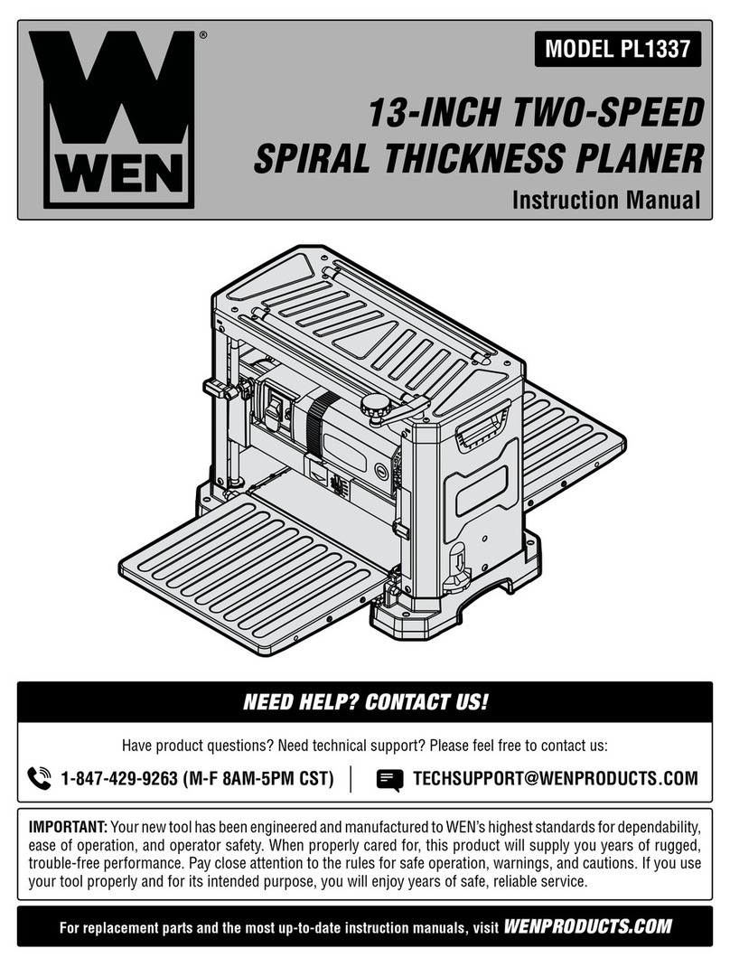
Wen PL1337 User manual

Wen

Wen PL1337 User manual

Wen PL1326 User manual

Wen

Wen PL1326 User manual

Wen 6528 User manual

Wen

Wen 6528 User manual

Wen 6528 User manual

Wen

Wen 6528 User manual

Wen 6550 User manual

Wen

Wen 6550 User manual

Wen 20653 User manual

Wen

Wen 20653 User manual

Wen 6550T User manual

Wen

Wen 6550T User manual

Wen PL1252 User manual

Wen

Wen PL1252 User manual

Wen 6550 User manual

Wen

Wen 6550 User manual

Wen 6530 User manual

Wen

Wen 6530 User manual

Wen 6530 User manual

Wen

Wen 6530 User manual

Wen 6530 User manual

Wen

Wen 6530 User manual

Wen 6550 User manual

Wen

Wen 6550 User manual

Wen PL1303 User manual

Wen

Wen PL1303 User manual

Popular Planer manuals by other brands

Scheppach Plana 3.0 Translation from the original instruction manual

Scheppach

Scheppach Plana 3.0 Translation from the original instruction manual

Felisatti PF180/1500 operating instructions

Felisatti

Felisatti PF180/1500 operating instructions

Melbourne MTC-49407 owner's manual

Melbourne

Melbourne MTC-49407 owner's manual

VARO POWERplus POW1520 manual

VARO

VARO POWERplus POW1520 manual

Powermatic 209 Operating instructions and parts manual

Powermatic

Powermatic 209 Operating instructions and parts manual

DeWalt DW 1150 Operation, adjustmants, maintenance, spare parts

DeWalt

DeWalt DW 1150 Operation, adjustmants, maintenance, spare parts

Triton TRP UL Operating and safety instructions

Triton

Triton TRP UL Operating and safety instructions

Palmgren 84115 Operating manual & parts list

Palmgren

Palmgren 84115 Operating manual & parts list

Makita 1051D instruction manual

Makita

Makita 1051D instruction manual

King Industrial CT-381FX Service manual

King Industrial

King Industrial CT-381FX Service manual

Delta Rockwell 22-101 manual

Delta Rockwell

Delta Rockwell 22-101 manual

Hammer A2-26 operating instructions

Hammer

Hammer A2-26 operating instructions

Grizzly G0663 owner's manual

Grizzly

Grizzly G0663 owner's manual

Raider PRO RDP-SEP20 solo user manual

Raider

Raider PRO RDP-SEP20 solo user manual

Charnwood W588 operating instructions

Charnwood

Charnwood W588 operating instructions

DeWalt DCP580B instruction manual

DeWalt

DeWalt DCP580B instruction manual

Bosch GHO 40-82 C Professional Original instructions

Bosch

Bosch GHO 40-82 C Professional Original instructions

Berner BP 40-82 C Original instructions

Berner

Berner BP 40-82 C Original instructions

manuals.online logo
manuals.online logoBrands
  • About & Mission
  • Contact us
  • Privacy Policy
  • Terms and Conditions

Copyright 2025 Manuals.Online. All Rights Reserved.

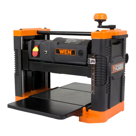
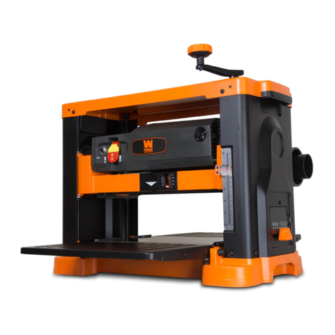
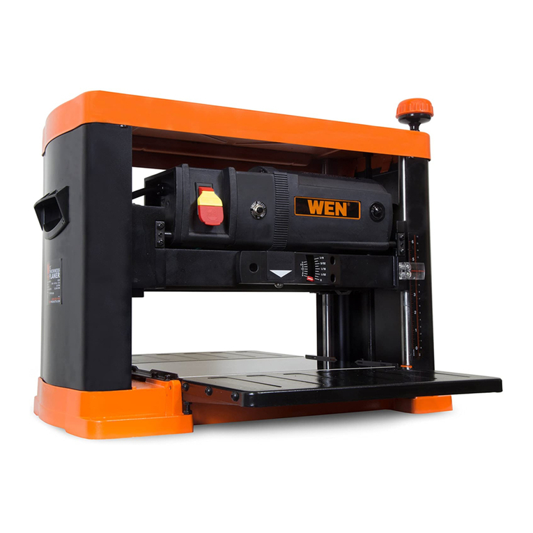
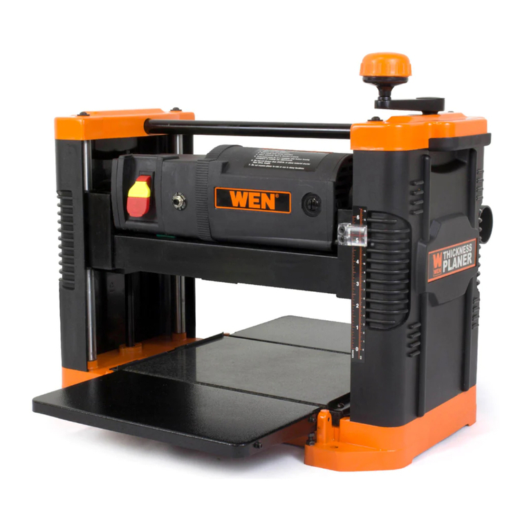
Model # 6552
13 IN.
THICKNESS PLANER
bit.ly/wenvideo
Your new tool has been engineered and manufactured to WEN’s highest standards for dependability,
ease of operation, and operator safety. When properly cared for, this product will supply you years
of rugged, trouble-free performance. Pay close attention to the rules for safe operation, warnings,
and cautions. If you use your tool properly and for intended purpose, you will enjoy years of safe,
reliable service.
IMPORTANT:
NEED HELP? CONTACT US!
Have product questions? Need technical support?
Please feel free to contact us at:
800-232-1195
[email protected]
WENPRODUCTS.COM
(M-F 8AM-5PM CST)
TABLE OF CONTENTS
Technical Data 2
3
4
5
7
7
10
13
14
15
17
General Safety Rules
Specific Safety Rules For Planer
Electrical Information
Know Your Planer
Assembly and Adjustments
Operation
Exploded View and Parts List
Warranty
TECHNICAL DATA
Model Number:
Motor:
Cutterhead Speed:
Number of Blades
Cuts Per Minute:
Feed rate:
Maximum Depth of Cut:
Table Size:
Infeed & Outfeed Table Size:
Base Size:
Workpiece Width (max.):
Workpiece Thickness (max.):
Dust Port Sizes:
Weight:
6552
120 V, 60 Hz, 15A
8500 RPM
3 blades
25500 cuts per minute
26 FPM
3/32˝
13-1/4 x 9-1/2˝
13-1/2 x 7-1/2˝
21-3/4 x 12-1/2˝
13˝
6˝
2˝, 2-1/2˝, & 4˝
77 lbs
2
Maintenance
Troubleshooting
3
GENERAL SAFETY RULES
Safety is a combination of common sense, staying alert and knowing how your item works. SAVE THESE SAFE-
TY INSTRUCTIONS.
WARNING: To avoid mistakes and serious injury, do not plug in your tool until the following steps
have been read and understood.
1. READ and become familiar with this entire instruction manual. LEARN the tool’s applications, limitations, and
possible hazards.
2. AVOID DANGEROUS CONDITIONS. Do not use power tools in wet or damp areas or expose them to rain.
Keep work areas well lit.
3. DO NOT use power tools in the presence of flammable liquids or gases.
4. ALWAYS keep your work area clean, uncluttered, and well lit. DO NOT work on floor surfaces that are slippery
with sawdust or wax.
5. KEEP BYSTANDERS AT A SAFE DISTANCE from the work area, especially when the tool is operating.
NEVER allow children or pets near the tool.
6. DO NOT FORCE THE TOOL to do a job for which it was not designed.
7. DRESS FOR SAFETY. Do not wear loose clothing, gloves, neckties, or jewelry (rings, watches, etc.) when op-
erating the tool. Inappropriate clothing and items can get caught in moving parts and draw you in. ALWAYS wear
non-slip footwear and tie back long hair.
8. WEAR A FACE MASK OR DUST MASK to fight the dust produced by sawing operations.
WARNING: Dust generated from certain materials can be hazardous to your health. Always oper-
ate the tool in a well-ventilated area and provide for proper dust removal. Use dust collection systems
whenever possible.
9. ALWAYS remove the power cord plug from the electrical outlet when making adjustments, changing parts,
cleaning, or working on the tool.
10. KEEP GUARDS IN PLACE AND IN WORKING ORDER.
11. AVOID ACCIDENTAL START-UPS. Make sure the power switch is in the OFF position before plugging in
the power cord.
12. REMOVE ADJUSTMENT TOOLS. Always make sure all adjustment tools are removed from the saw before
turning it on.
13. NEVER LEAVE A RUNNING TOOL UNATTENDED. Turn the power switch to OFF. Do not leave the
tool until it has come to a complete stop.
14. NEVER STAND ON A TOOL. Serious injury could result if the tool tips or is accidentally hit. DO NOT store
anything above or near the tool.
4
15. DO NOT OVERREACH. Keep proper footing and balance at all times. Wear oil-resistant rubber-soled foot-
wear. Keep the floor clear of oil, scrap, and other debris.
16. MAINTAIN TOOLS PROPERLY. ALWAYS keep tools clean and in good working order. Follow instruc-
tions for lubricating and changing accessories.
17. CHECK FOR DAMAGED PARTS. Check for alignment of moving parts, jamming, breakage, improper
mounting, or any other conditions that may affect the tool’s operation. Any part that is damaged should be properly
repaired or replaced before use.
18. MAKE THE WORKSHOP CHILDPROOF. Use padlocks and master switches and ALWAYS remove start-
er keys.
19. DO NOT operate the tool if you are under the influence of drugs, alcohol, or medication that may affect your
ability to properly use the tool.
20. USE SAFETY GOGGLES AT ALL TIMES that comply with ANSI Z87.1. Normal safety glasses only have
impact resistant lenses and are not designed for safety. Wear a face or dust mask when working in a dusty environ-
ment. Use ear protection such as plugs or muffs during extended periods of operation.
GENERAL SAFETY RULES
SPECIFIC RULES FOR THE PLANER
1. Whenever adjusting or replacing any parts on planer, turn switch OFF and remove plug from power source.
2. Make sure all guards are properly attached and securely fastened.
3. Make sure all moving parts are free from interference.
4. Always wear eye protection or face shield.
5. Make sure blades are aligned and properly attached to cutterhead.
6. Do not plug in planer unless the switch is in the off position. After turning the switch on, allow the planer to
come to full speed before operating.
WARNING: For your own safety, read all of the instructions and precautions before operating tool.
WARNING: Operation of any power tool can result in foreign objects being thrown into eyes which
can result in severe eye damage. Always wear safety goggles complying with United States ANSI Z87.1
(shown on package) before commencing power tool operation.
CAUTION: Always observe the following safety precautions:
5
SPECIFIC RULES FOR THE PLANER
ELECTRICAL INFORMATION
GROUNDING INSTRUCTIONS
IN THE EVENT OF A MALFUNCTION OR BREAKDOWN, grounding provides the path of least resistance
for an electric current and reduces the risk of electric shock. This tool is equipped with an electric cord that has an
equipment grounding conductor and a grounding plug. The plug MUST be plugged into a matching outlet that is
properly installed and grounded in accordance with ALL local codes and ordinances.
DO NOT MODIFY THE PLUG PROVIDED. If it will not fit the outlet, have the proper outlet installed by a
licensed electrician.
IMPROPER CONNECTION of the equipment grounding conductor can result in electric shock. The conduc-
tor with the green insulation (with or without yellow stripes) is the equipment grounding conductor. If repair or
replacement of the electric cord or plug is necessary, DO NOT connect the equipment grounding conductor to a
live terminal.
CHECK with a licensed electrician or service personnel if you do not completely understand the grounding instruc-
tions or whether the tool is properly grounded.
CAUTION: In all cases, make certain the outlet in question is properly grounded. If you are not sure, have a li-
censed electrician check the outlet.
7. Keep hands clear of all moving parts.
8. Do not force cut. Slowing or stalling will overheat motor. Allow automatic feed to function properly.
9. Use quality lumber. Blades last longer and cuts are smoother with good quality wood.
10. Do not plane material shorter than 15”, narrower than 3/4”, wider than 13” or thinner than 1/2”.
11. Never make planing cut deeper than 3/32".
12. For workpieces longer than 24", use material support stands.
13. Do not back the work towards the infeed side.
14. Take precautions against kickback. Do not permit anyone to stand or cross in line of cutterhead’s rotation.
Kickback or thrown debris will travel in this direction.
15. Turn switch off and disconnect power whenever planer is not in use.
16. Replace knives as they become damaged or dull.
17. Keep planer maintained. Follow maintenance instructions.
6
WARNING: This tool is for indoor use only. Do not expose to rain or use in damp locations.
Guidelines for using extension cords
Make sure your extension cord is in good condition. When using an extension cord, be sure to use one heavy
enough to carry the current your product will draw. An undersized cord will cause a drop in line voltage resulting
in loss of power and overheating. The table below shows the correct size to be used according to cord length and
nameplate ampere rating. When in doubt, use a heavier cord. The smaller the gauge number, the heavier the cord.
Make sure your extension cord is properly wired and in good condition. Always replace a damaged extension cord
or have it repaired by a qualified person before using it.
Protect your extension cords from sharp objects, excessive heat and damp/wet areas.
Use a separate electrical circuit for your tools. This circuit must not be less than a #12 wire and should be protected
with a 15 A time-delayed fuse. Before connecting the motor to the power line, make sure the switch is in the OFF
position and the electric current is rated the same as the current stamped on the motor nameplate. Running at a
lower voltage will damage the motor.
WARNING: This tool must be grounded while in use to protect the operator from electric shock.
ELECTRICAL INFORMATION
AMPERAGE
REQUIRED GAUGE FOR EXTENSION CORDS
25 ft. 50 ft. 100 ft. 150 ft.
15 A 14 gauge 12 gauge 10 gauge 8 gauge
Circuit
Breaker
CIRCUIT BREAKER
The planer is equipped with a motor pro-
tection device-circuit breaker. The breaker
will automatically shut the planer off when
excessive current is consumed. If the
breaker is tripped, turn the planer off and
reset the circuit by pressing the button.
CAUTION: Be sure to turn the planer
off prior to resetting the circuit breaker to
avoid unintentional start-up of the planer.
UNPACKING (FIGURE 1)
The planer comes assembled as one unit. Additional parts which need to be fastened to planer should be located
and accounted for before assembling.
WARNING: Do not attempt assembly if parts are missing. Use this manual to order replacement parts.
7
KNOW YOUR PLANER
ASSEMBLY AND ADJUSTMENTS
Infeed Table
Circuit Breaker
Power Switch
Carrying Handle
Crank Handle
Figure 1
Dust Port
Roller Extensions
Thickness Planer Dust Chute Thumb
Screw (x2)
Magnet (x2)
Dust Chute
Adapter
Crank
Handle Socket
Head
Bolt
Flat
Washer
Hex
Wrench
88
ASSEMBLY AND ADJUSTMENTS
PREPARING THE TABLES (FIGURES 3 - 6)
Unwrap the power cord from the cord storage underneath the outfeed table. Lower the infeed and outfeed tables.
ATTACHING THE CRANK HANDLE (FIGURE 2)
Place the washer over the socket head bolt and feed the bolt into
the handle. Tighten the bolt to secure the handle in position
on top of the planer. Place the handle cap onto the handle as
shown in Figure 4.
Figure 3 Figure 4
Remove the polystyrene insert located between the main table and the blade drum. Peel back the protective film
insert from the main table.
Figure 2
Figure 5 Figure 6
9
MOUNT PLANER TO WORK SURFACE (FIGURE 8 - 9)
The planer is designed to be portable so it can be moved to a job site. However, it should always be mounted to
a stable, level bench or table in a place with ample lighting and correct power supply. Make sure there is plenty
of room for moving the workpiece through the entire cut. Neither the operators or the bystanders should have to
stand in line with the wood while using the tool.
The base of the planer has four mounting holes. Mount the planer to the workbench or to the tool stand using
bolts, flat washers and hex nuts (not supplied). Figure 8 shows the base dimensions, mounting holes and required
space to allow for table assembly. Securely mount the planer to the work table by bolting it through the holes.
Make sure the planer does not rock and that the work table is level.
ATTACH DUST CHUTE (FIGURE 7)
Planer is best used along with a dust collec-
tor. Dust chute is included. The dust chute is
mounted to the rollercase using two thumb
screws. The dust chute can be mounted to
direct chips to either side of planer.
After mounting, connect wet/dry vacuum
hose to dust chute. Be sure to turn the
ASSEMBLY AND ADJUSTMENTS
Figure 7
vacuum on before operating the planer. An adapter is provided for better matching dust extraction systems.
Figure 8 Figure 9
Hole for
Mounting
10
OPERATION
The WEN 13-Inch Planer planes soft and hardwoods up to 6" thick and 13" wide. Wood feeds into the two-blade
cutterhead by rubber infeed/outfeed rollers. Planer can take cuts up to 3/32" per pass at 26 feet per minute.
WARNING: Do not connect planer to the power source until all assembly steps have been completed.
ON/OFF SWITCH (FIGURE 10)
The ON/OFF switch is located on the front of the planer motor. To
turn the planer ON, move the switch to the up position. To turn the
planer OFF, move the switch to the down position.
SWITCH LOCK (FIGURE 11)
Remove the red tab to engage child-safety lock and prevent unwanted
start-ups. To lock the switch:
Turn the switch to OFF position and disconnect planer from power
source. Pull the key out. The switch cannot be turned on with the
key removed. To replace key, slide key into the slot on switch until it
snaps.
NOTE: The key can be removed from the switch while in the ON
position. This allows for the device to be turned off but still prevents it
from being turned back on.
AVOID DAMAGE TO BLADES
Thickness planers are a precision woodworking machine and should be used on quality lumber only. Do not
plane dirty boards; dirt and small stones are abrasive and will wear out blade.
REMOVE NAILS AND STAPLES. Use planer to cut wood only.
Avoid knots. Heavily cross-grained wood makes knots hard. Knots can come loose and jam blade.
WARNING: Any article that encounters planer blades may be forcibly ejected from planer creating risk
of injury. Make sure the wood is free from outside materials before attempting to plane.
Figure 10
Figure 11
DEPTH OF CUT (FIGURE 12)
Rotate the crank handle to adjust the height of the cutterhead. The depth scale shows the height of the cutterhead
above the main table. Quality of thickness planing depends on the operator’s judgement about the depth of cut.
Depth of cut depends on the width, hardness, dampness, grain direction and grain structure of the wood. Maxi-
mum thickness of wood which can be removed in one pass is 3/32” for planing operations.