5
ALLGEMEINES
DIGI-TOOL F6xx ist ein aktiver Anpass-, Auf-
hol- und Verteilverstärker für digitale Signale.
Je nach Ausführung können AES/EBU, WCLK
oder AES-id Signale bearbeitet werden.
Durch die empfindliche Elektronik können
schwache und verschliffene Signale aufge-
frischt werden, durch starke und schnelle Aus-
gangstreiber können lange Leitungen betrieben
werden.
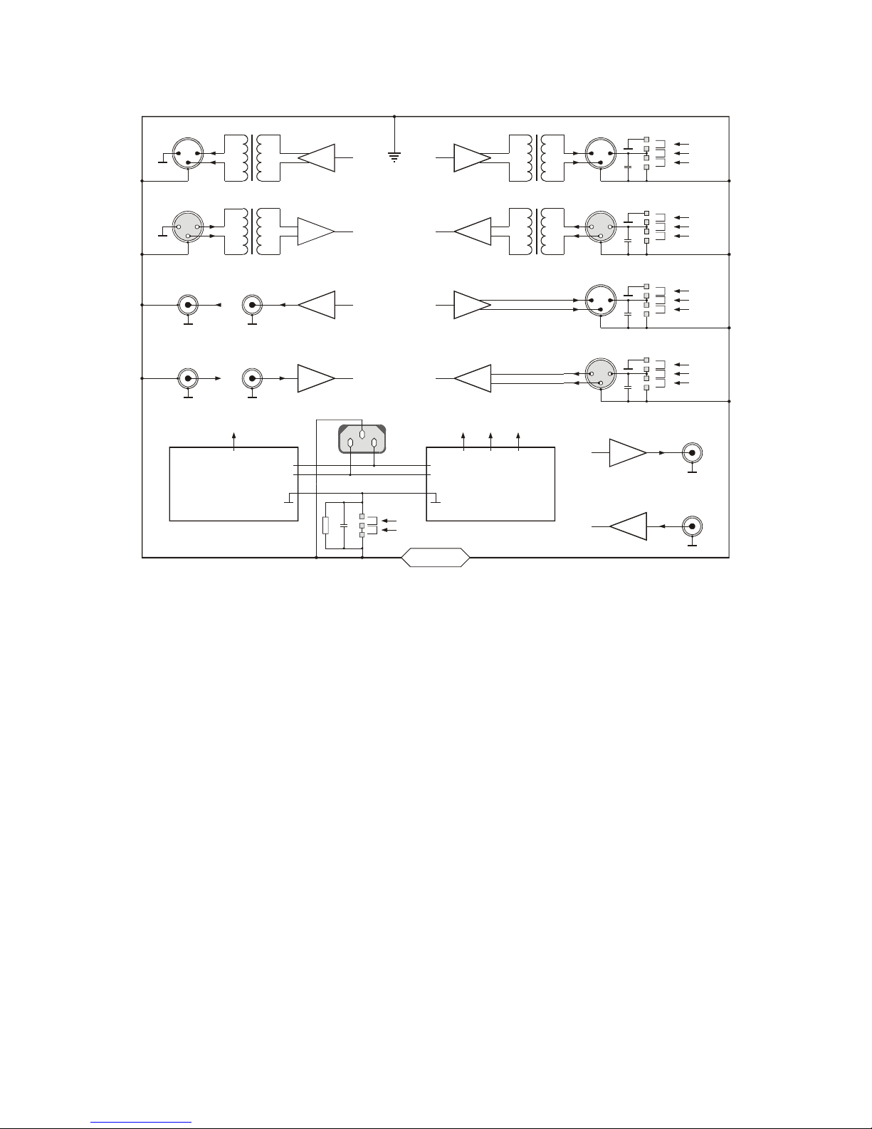
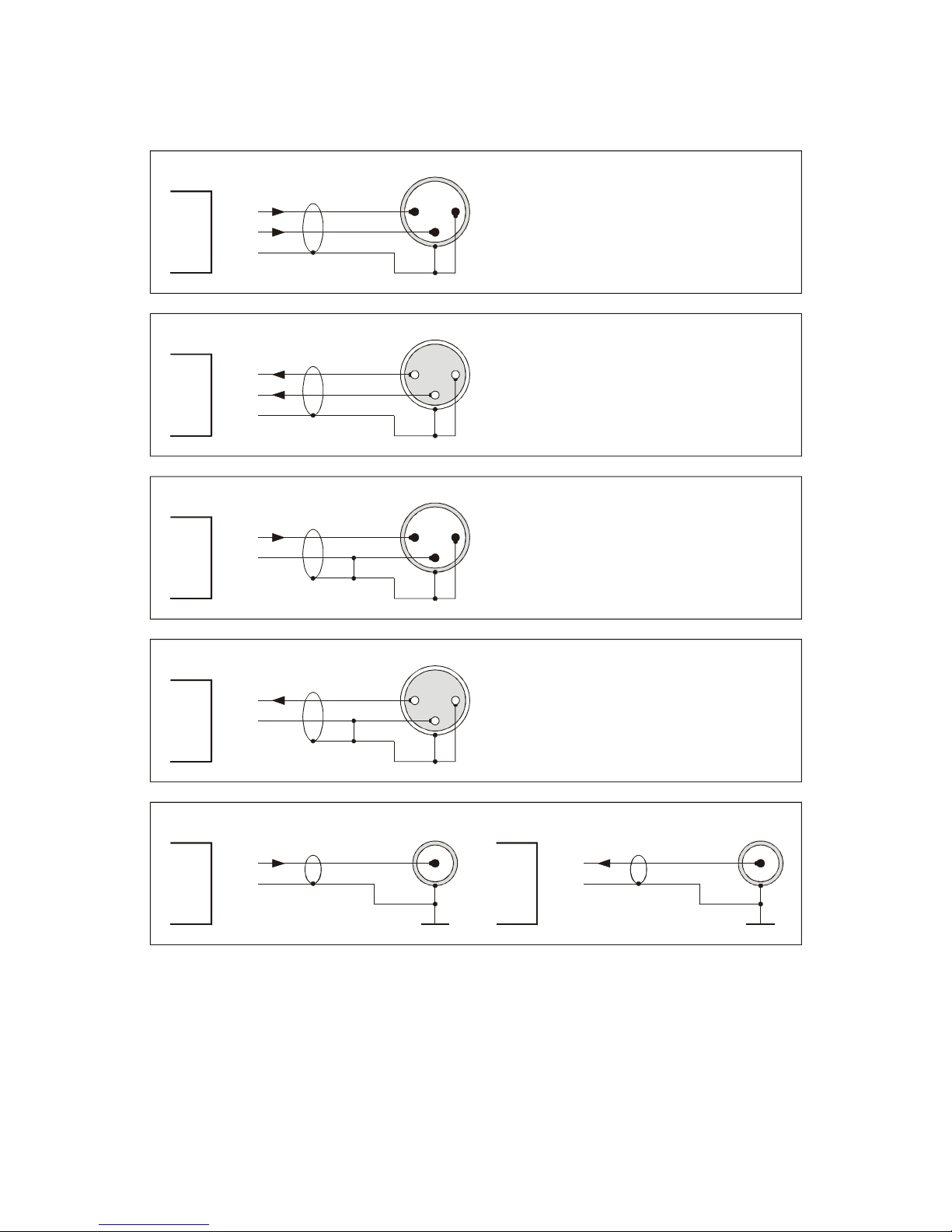
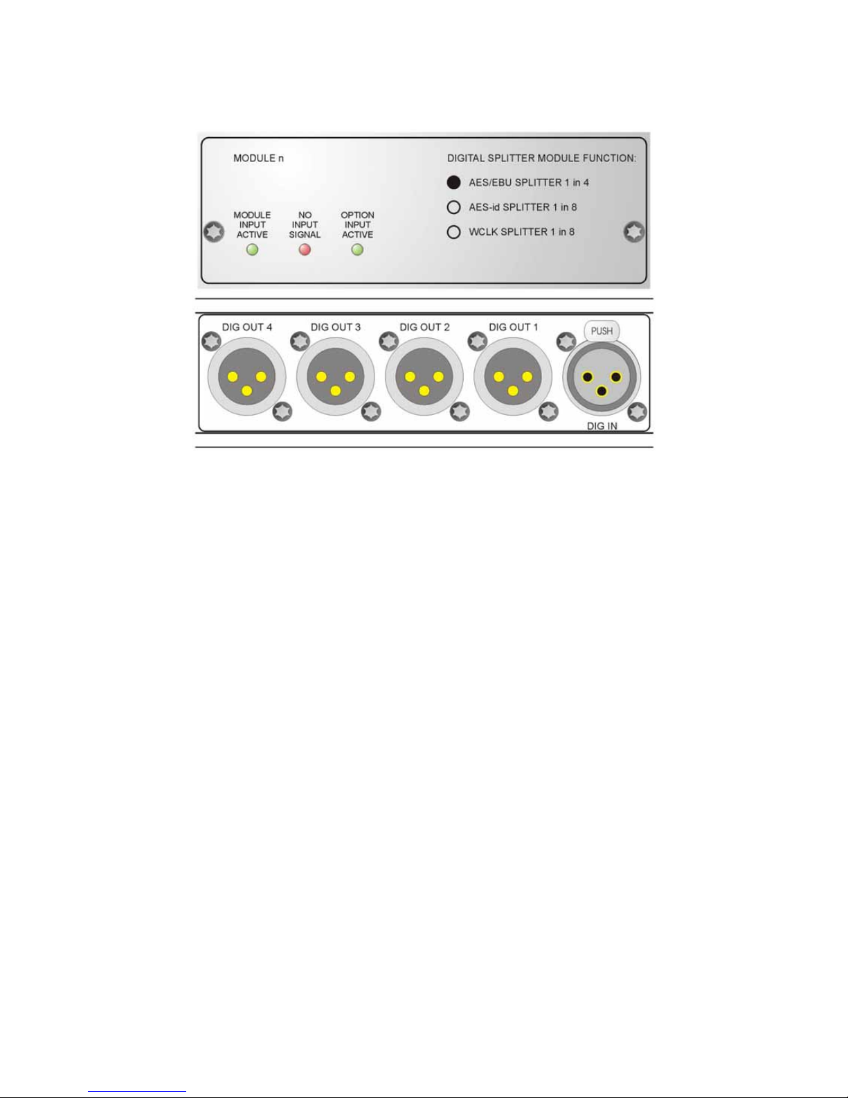
DIGI-TOOL F611 ist als Verteilverstärker für
AES/EBU Signale gedacht und besteht aus 2
Modulen mit je einem Eingang und vier
Ausgängen. Alle Ein- und Ausgänge sind
trafosymmetrisch über XLR.
Auf Anfrage lieferbar ist DIGI-TOOL F610,
bestehend aus einem Modul mit 1 Eingang auf
4 Ausgänge für AES/EBU Signale.
DIGI-TOOL F622 ist als Verteilverstärker für
WCLK bzw. AES-id Signale gedacht und
besteht aus zwei Modulen mit je einem Eingang
und acht Ausgängen. Die Ein- und Ausgänge
sind unsymmetrisch über BNC.
Auf Anfrage lieferbar ist DIGI-TOOL F620,
bestehend aus einem Modul mit 1 Eingang auf
8 Ausgänge für WCLK bzw. AES-id.
DIGI-TOOL F612 ist ein Verteilverstärker mit je
einem AES/EBU Modul und einem WCLK bzw.
AES-id Modul.
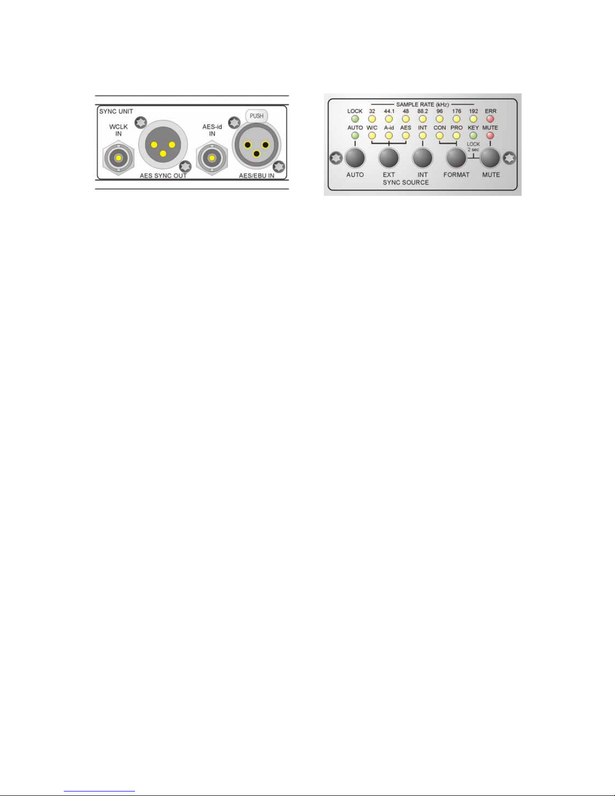
SYNC OPTION
Optional kann DGI-TOOL F6xx mit einer Sync
Einheit mit folgenden Funktionen ausgerüstet
werden:
- AES/EBU Input
Einem AES Signal wird die Fs und 256 Fs
Information entzogen. Über das WCLK Modul
kann ein synchroner Wordclock erzeugt
werden.
- AES-id Input
Einem AES-id Signal wird die Fs und 256 Fs
Information entzogen. Über das WCLK Modul
kann ein synchroner Wordclock erzeugt
werden.
- WCLK Input
Ein Wordclock Signal kann über das
AES/EBU Modul als AES-Sync ausgegeben
werden.
- AES/EBU Output
An diesem Ausgang steht immer ein AES-
Sync Signal.
- Interne Oszillatoren
Die Oszillatoren erzeugen 32, 44.1, 48, 88.2,
96, 176,4 und 192 kHz. Diese Frequenzen
können über die entsprechenden Module als
AES-Sync, AES-id-Sync oder Wordclock aus-
gegeben werden.
Mehr zur Funktionalität dieses Moduls siehe
Seite 9.
DAS GEHÄUSE
Das geerdete Gehäuse besteht aus 1 - 2 mm
starkem Edelstahl. Dies garantiert eine hohe
mechanische Stabilität und Widerstands-
fähigkeit gegen rauhe Umwelteinflüsse.
Durch die hohe elektrische Leitfähigkeit der
unbehandelten Oberflächen ergeben sich
hervorragenden EMV Eigenschaften.
DIE STROMVERSORGUNG
Die Stromversorgung erfolgt über eine einge-
baute IEC-CEE-Dose. Das Primär getaktete
Netzteil besitzt einen Multi-Mode Eingang für
Netzspannungen von 90 ... 260 V AC.
Der "POWER"-Schalter befindet sich auf der
Frontplatte. Der eingeschaltete Zustand wird
durch eine LED unter dem "POWER"-Schalter
angezeigt.
Das Netzteil erzeugt eine stabile 5 V DC
Spannung zur Versorgung der digitalen
Komponenten.
DIE NETZSICHERUNG
Die Sicherung ist intern auf dem Netzteil-Print
verlötet.
ACHTUNG !!
SICHERHEITSHINWEISE BEACHTEN:
Eine durchgebrannte Sicherung weist auf inter-
ne Probleme hin und sollte nur im Rahmen von
qualifizierten Service- oder Reparaturarbeiten
ersetzt werden !!