Lance Design ADX-8000 User manual

ADX-8000
DUAL POWER SUPPLY AND
ETHERNET SWITCH
Installation and Operation Manual
Firmware Version 1.2
Lance Design / 27 Fairview Avenue / Ridgefield, Connecticut 06877
Tel: 203-894-8206 / Fax: 203-894-8207
www.lancedesign.com

2
WARRANTY STATEMENT
This equipment is warranted to be free of defects in materials and workmanship for
a period of two years from date of delivery. Any necessary repairs resulting from
defects in materials or in manufacture will be made free of charge provided that the
equipment has not been subjected to mechanical or electrical abuse, or modification,
as determined by Lance Design, and also that the equipment is returned to Lance
Design with prior authorization.
No liability whatsoever is assumed for consequential damages resulting from the use
or failure of this equipment. This warranty is in lieu of all other warranties,
expressed or implied, including any implied warranty of fitness for purpose.
COPYRIGHT
All software and hardware designs are copyrighted to Lance Design, 2010-2017.

3
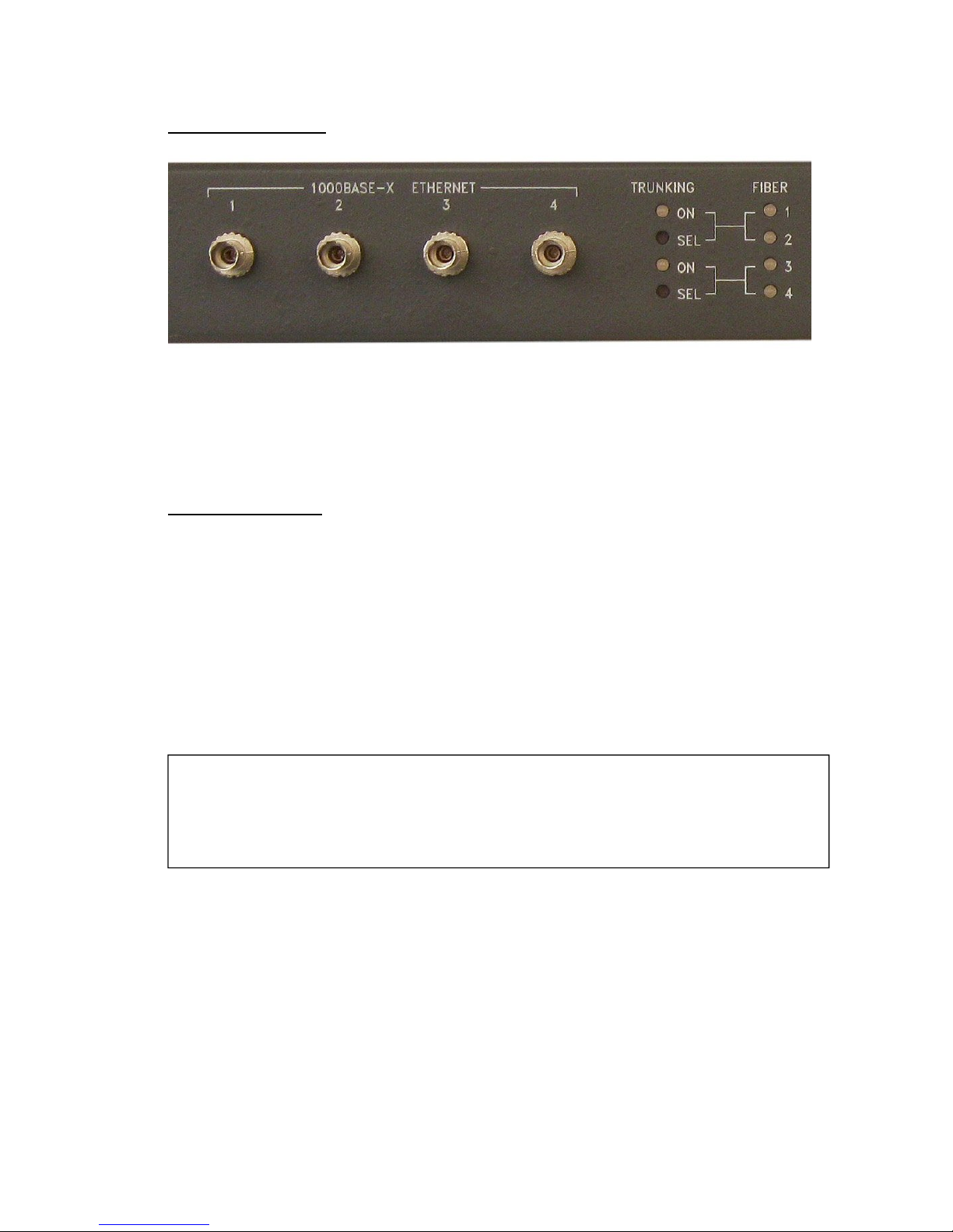
ADX-8000 Front Panel View
DESCRIPTION
The ADX-8000 is a dual (redundant) power supply unit and twelve port Ethernet
switch, intended for use with ADX-120 and ADX-140 networked audio devices.
It is designed to be placed in announce booths or similar applications to provide
power and fiber connectivity for ADX-series remote devices.
FEATURES
Eight 100baseT Copper Ethernet ports with 48-volt DC power on the
spare pairs. These ports are configured to match the requirements of
ADX-120 Announce Units and ADX-140 XLR Interface Units, providing
both power and network connectivity.
Four Gigabit Ethernet Fiber Ports to provide fiber links to the mobile unit
or control room via single-mode, bidirectional fiber. These ports utilize
standard SFP modules, but the modules are located inside the cabinet so
that they are protected from damage in broadcast field environments.
Only a single strand of fiber is required for system operation, two may be
used for redundancy. Two additional ports are available for any other
application such as linking to a secondary location, providing a very high
level of flexibility.
Dual fully-redundant and load sharing power supplies supply power to
both the switch and the ADX-120 and ADX-140 units. These highly-
reliable, high-efficiency power supplies feature wide-range AC inputs for
operation world-wide.
Auxiliary 48-volt DC input on an industry-standard 4-pin XLR connector
allows the entire system to be operated from a battery supply in the event
that AC power is not available.
Full front-panel status monitoring of power supply status, internal
temperatures, switch health, copper and fiber link and activity status, and
fiber RX power.
Simple operation - no web-based configuration required.

4
SYSTEM CONNECTIONS
The diagram below illustrates a typical simple configuration utilizing the ADX-8000.
The booth consists of three ADX-120 Announce Units and an ADX-140 XLR
Interface Unit, and the ADX-8000 Power Supply / Switch.
The mobile unit end of the system consists of an ADX-2400 base unit and a generic
ethernet switch or media converter. (An ADX-8000 could be used for this purpose
also if desired)
The network connections are very simple and straight-forward. The ADX-2400 in
the mobile unit is connected to a generic gigabit switch, such as a Netgear GS716.
One of the switch fiber ports is connected via single-mode fiber to one of the fiber
ports on the ADX-8000 in the booth.
The ADX-120s and ADX-140 are connected to any of the ADX PORTS on the ADX-
8000. DC Power should be turned on for the ADX ports to power the 120s and
140s.

5
FIBER PORTS 1-4
There are four ST connectors which are single-mode, bi-directional gigabit ethernet
fiber ports. These panel-mounted ST connectors are connected internally to
industry-standard SFP modules.
Since the ports are bi-directional, a fiber link requires only a single strand of fiber.
IMPORTANT NOTE
Since the SFP modules are bi-directional they transmit on one wavelength and
receive on a different wavelength. This means that the modules on the two ends of
a fiber link must be complementary; transmit on one end must match receive on the
other end and vice versa.
By industry convention, there are two types of SFP modules:
TYPE A (BLUE plastic handle) TX on 1310 nm, RX on 1550 nm.
TYPE B (YELLOW plastic handle) TX on 1550 nm, RX on 1310 nm.
The modules may be changed by removing the top cover if a different configuration
is required.
The 'FIBER' status leds will light green if a good link is established, and will flash
when there is network traffic.
If the received optical power level is low (-17dBm or lower) the led color will change
to yellow, indicating a dirty fiber or lossy fiber path.
Most ADX-8000s are shipped with TYPE B (Yellow) modules in ports 1 and 2,
and TYPE A (Blue) modules in ports 3 and 4. Some units have different
configurations to match certain customer's existing standards or for special
requests. Please see the labels below the ST connectors for the configuration
of your unit.

6
FIBER TRUNKING AND REDUNDANT (A/B) FIBER OPERATION
There are two 'TRUNKING' leds, and two pushbutton switches immediately to the
left of the 'FIBER' status leds. These indicate and enable/disable trunking or 'link
aggregation' for the fiber port 1/2 pair and the port 3/4 pair.
The trunking modes are indicated by the state of the trunking LED associated with a
pair of fiber ports (1/2 or 3/4). The mode may be changed by pressing and holding
the 'SEL' pushbutton for one second. Use a small screwdriver or other simirlar tool
to press and hold the 'SEL' pushbuttons.
Starting with version 1.2 firmware, there are three possible modes for the trunking
selection. Pressing the 'SEL' button as described above will step through the three
modes.
MODE 1 - OFF (LED off)
This disables all trunking or redundant fiber operation, and each of the four fiber
ports is completely independent. Use this mode if each fiber port in use is
connected to a different switch, and there are no parallel connections or loops in the
network.
MODE 2 - LINK AGGREGATION ON (LED steadily lit)
This is true trunking, or link aggregation, typical of other ethernet switches. Trunking
(or 'link aggregation') is a method by which multiple links between two switches can
be combined into a single logical link. The traffic is shared between the two links so
long as both links are up. Should one link fail all traffic is routed to the other link.
This method may be used to establish redundant fiber paths between two switches
provided that the switches on both ends of the links can support link aggregation.
This requires that the switch on the other end be a managed switch, and be
configured for link aggregation also.
The switches on both ends of the links must support this mode for it to work
properly.
(continued)

7
MODE 3 - A/B AUTO-CHANGEOVER (LED blinking)
(Ver 1.2 firmware and later)
This is a special mode that does NOT use link aggregation, but supports automatic
switching of fiber paths at the ADX-8000 should the primary path fail. It does not
require that the switch on the other end support trunking, so it can be an unmanaged
switch or even two separate switches.
All traffic is routed to the first link (1 or 3) unless that link fails, and then if the backup
link (2 or 4) is functional it switches traffic to the backup.
Only one port of the pair is active at any one time.
The switch on the other end of the links must NOT have port aggregation enabled to
use this mode, since all traffic must be received on the active port.
Note that the 'link' LED on the other switch's backup link will not be lit unless the
primary port fails and the backup link is operative.
Most off-the-shelf managed switches require the use of a web browser to configure
link aggregation or trunking. Consult the manufacturer's documentation for the
relevant details.
The trunking LED will be yellow if mode 2 or mode 3 is selected, but only one fiber
link is operating. It will be green if both links are up.
If you're using two fiber links between switches either MODE 2 or MODE 3
must be selected, or you will have created a network loop, and the network
won't function.

8
ADX PORTS (COPPER ETHERNET)
There are eight copper 100baseT ethernet ports intended for connection to ADX-120
Announce Units or ADX-140 XLR Interface Units.
There are DC POWER switches for each group of four. If these switches are on,
48-volt DC voltage will be applied to the spare wire pairs in the RJ-45 connectors,
appropriate for powering the 120s and 140s. This applied voltage is indicated by the
yellow led adjacent to the connector.
(Note that the ADX-140s also have an AC power input. Either or both may be used).
The voltage is supplied by dual redundant high-efficiency power supplies.
Only a single CAT5 (or Cat5E or Cat6) cable is required between the ADX-8000 and
each ADX-120 or ADX-140.
It makes no difference which ports are connected to which ADX-120 or ADX-140;
they are all identical.
Cable length may be up to the ethernet maximum of 100 meters.
The ADX-8000 ports will automatically sense the RX/TX wiring, so crossover cables
are not required, but are permissible. (Auto MDI-X).

9
STATUS LEDS
There are four status leds on the front panel
PS 1 GREEN if power supply 1 is operating properly
FLASHING RED if power supply 1 output is out of limits
PS 2 GREEN if power supply 2 is operating properly
FLASHING RED if power supply 2 output is out of limits
TEMP GREEN if internal temperatures are within limits
FLASHING RED if temperature is too high.
SYSTEM GREEN if self-test of switch chip is ok
FLASHING RED if a switch fault is detected
Note that if external DC power is being used instead of AC power, the PS1 and PS2
leds will blink GREEN if the external power is within limits, and will blink RED if the
external voltage is too low, possibly indicating that an external battery supply is
reaching the end of its charge.

10
Table of contents
Popular Network Router manuals by other brands

Flyingvoice
Flyingvoice G702 user guide

3One data
3One data ICPE2300A-BW-8A25-1GC3GT-PD2P12 48 Quick installation guide

Watchguard
Watchguard Wireless Router quick start guide

Planet
Planet XRT-401F installation guide

NetComm Wireless
NetComm Wireless NTC-6200 user guide

VPInstruments
VPInstruments VPRouter quick start guide