2-1
TABLE OF CONTENTS Chapter 2
Component Overview
General
IMPORTANT
First read and understand the operators manual.
Second, always conduct a Receipt Inspection on your
new equipment to verify that it is complete and not
damaged prior to placing it into operation. Report any
findings to the Landoll Trailer Service Contacts at
Landoll.com or phone 800-446-5175 / 888-522-3634.
See Receipt Inspection Checklist on Page 4-6.
This section provides the component locations and
descriptions for the Electric Hydraulic Power unit.
Operators must be familiar with the components,
instructions and safety statements before operating the
power unit.
The Electric Hydraulic Power option is a quick attach
enclosed rechargeable battery powered electric motor
driven hydraulic pump unit, that supplies external
hydraulic power to a system.
DANGER
DANGER
DANGER
DANGER
WARNING
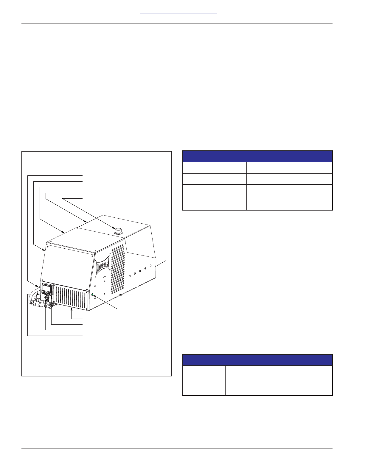
Enclosure
The metal enclosure can be mounted on the front end of
the Landoll Trailer or above the optional winch. It provides
protection and a mounting surface for the power unit’s
electrical and hydraulic components. The enclosure
measures 52 inches long, 24 inches wide and 24 inches
high (132.08cm x 60.96cm x 60.96cm). DO NOT use high
pressure water to clean on or near the power unit
assembly. This can result in damage to the electrical
components mounted inside and outside of the enclosure.
Failure to comply may lead to death, severe injury
or damage to equipment. Requires complex
electrical system troubleshooting and repair. It is
highly recommended to contact the Landoll
Trailer Service Department at Landoll.com or
phone 800-446-5175 / 888-522-3634.
1. SHOCK HAZARD - Batteries are in a parallel
circuit, this increases the system’s amps,
capacity and energy. Use proper insulated
tools and procedures when working with
batteries.
2. SHOCK HAZARD - DO NOT touch any
terminals, Use proper insulated tools and
procedures when working with batteries.
3. MAGNETIC FIELD - The motor generates high
magnetic fields and are hazardous to
individuals with pacemakers. Individuals with
pacemakers DO NOT work on motor.
4. DO NOT operate the equipment until you have
read the operator’s manual and completely
understand the proper use and function of all
controls
5. DO NOT operate the equipment with broken,
defective or missing parts.
6. REPLACE defective, damaged and leaking
batteries. Exposure to the battery contents
may release flammable liquid and vapors, may
cause allergic skin reactions or damage
organs, and may cause cancer.
7. ALWAYS check above, below and around the
equipment for persons and objects before
moving.
8. To prevent serious injury or death from
pinching: Keep all persons and objects clear
while any part of the machine is in motion.
9. ALWAYS fully couple truck to trailer when
operating the hydraulics. Trailer may become
unstable and lose contact with the ground.
Failure to comply may lead to death, serious
injury or damage to equipment. Requires
complex electrical system troubleshooting and
repair. It is highly recommended to contact the
Landoll Trailer Service Department at
Landoll.com or phone 800-446-5175 /
888-522-3634.
1. MAGNETIC FIELD - The motor generates high
magnetic forces and can attract items quickly.
Wear gloves, hold on to tools / items tightly
and move slowly.
2. ALWAYS connect hydraulic quick couplers
before operating.
3. DO NOT use high pressure water on or near
the enclosure. May cause damage to the
electrical components or wiring of the Electric
Hydraulic Power unit.