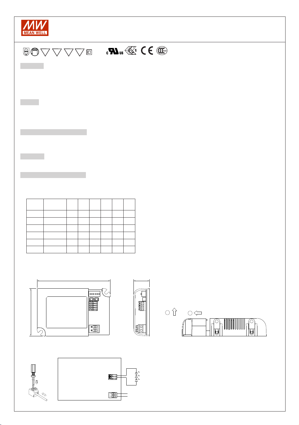
Meanwell LCM-25 User manual

Other Meanwell Power Supply manuals

Meanwell
Meanwell EDR-75-12 User manual

Meanwell
Meanwell RCB-1600 Series User manual

Meanwell
Meanwell HDR-15 Series User manual

Meanwell
Meanwell SHP-10K-HV Series User manual

Meanwell
Meanwell NDR-75-12 User manual

Meanwell
Meanwell LCM-25 User manual

Meanwell
Meanwell IRC1 User manual

Meanwell
Meanwell ICL-16L Series User manual

Meanwell
Meanwell DDR-120 Series User manual

Meanwell
Meanwell DRP-3200 Series User manual

Meanwell
Meanwell APV-25 User manual

Meanwell
Meanwell KNX-20E-640 User manual

Meanwell
Meanwell AP User manual

Meanwell
Meanwell TDR-240-24 User manual

Meanwell
Meanwell RHP-1U Series User manual

Meanwell
Meanwell HEP-1000 User manual
 User manual")
Meanwell
Meanwell LCM-40(DA) User manual

Meanwell
Meanwell TDR-480-24 User manual

Meanwell
Meanwell DR-RDN20 User manual

Meanwell
Meanwell DRA-40 Series User manual


Popular Power Supply manuals by other brands


Puls
Puls ML100.105 installation manual

Vertiv
Vertiv NetSure IPE Series Installation and user manual

OmniPower
OmniPower POWERCADDY PS Series user manual

Thermo Scientific
Thermo Scientific Invitrogen PowerEase Touch PS0120 user guide

VHF Engineering
VHF Engineering PS-15C instruction manual

Risen
Risen RSM60-6 P Series Module Installation and Maintenance Manual


