FEAS PSW7012 User manual
Beim Umgang mit Produkten, die mit elektrischen Spannungen in Berührung kommen, müssen die
gültigen VDE / IEC / EN Vorschriften beachtet werden. Besonders sei auf folgende Vorschriften
hingewiesen: VDE 0100, VDE 0550 / 0551, VDE 0711, VDE 0860, IEC 664, IEC 742, IEC 570, IEC 65
Bei Nichtbeachtung der Bedienungsanleitung oder der Anschlußvorschrift, z.B. bei
Vertauschen der Anschlußklemmen, kann das Gerät oder die Anlage beschädigt werden und
der Betreiber verliert seinen möglichen Haftungsanspruch.
Werkzeuge dürfen an Geräten, Bauteilen oder Baugruppen nur benutzt werden, wenn
sichergestellt ist, daß die Geräte von der Versorgungsspannung getrennt
sind und elektrische Ladungen die in im Gerät befindlichen Bauteile gespeichert
sind, vorher entladen wurden.
Vor dem Öffnen des Gerätes den Netzstecker ziehen oder sicherstellen, daß das Gerät
stromlos ist. Bauteile, Baugruppen oder Geräte dürfen nur in Betrieb genommen werden,
wenn sie vorher in ein berührungssicheres Gehäuse eingebaut wurden. Während des
Einbaus müssen sie stromlos sein.
Spannungsführende Kabel oder Leitungen mit denen das Gerät, das Bauteil oder die
Baugruppe verbunden sind müssen stets auf Isolationsfehler oder Bruchstellen untersucht
werden. Bei Feststellen eines Fehlers in der Zuleitung muß das Gerät unverzüglich aus dem
Verkehr genommen werden, bis die defekte Leitung ausgewechselt worden ist.
Der Anwender hat dafür Sorge zu tragen, daß die angegebenen Gerätedaten nicht
überschritten werden.
Wenn aus den vorgelegten Beschreibungen für den Anwender oder Erwerber nicht eindeutig
hervorgeht, welche Kennwerte für ein Gerät oder Bauteil gelten, so muß stets ein Fachmann
um Auskunft ersucht werden.
Im übrigen unterliegt die Einhaltung von Bau- und Sicherheitsvorschriften aller Art ( VDE, TÜV,
Berufsgenossenschaften ) dem Anwender / Käufer.
Allgemeine Sicherheitsvorschriften :
When working with products which are in contact to dangerous electrical voltages, attention must
be payed to the relevant valid VDE / IEC / EN regulations. Especialy with refrence to the following
rules: VDE 0100, VDE 0550 / 0551, VDE 0711, VDE 0860, IEC 664, IEC 742, IEC 570, IEC 65
In case of non-observance of this instructions, the unit or other equipment might be damaged
and no warranty or liability could be accepted.
When it is necessary to use tools with the units, components parts or subassemblies make it
sure, that the power is disconnected from the units and all electric charge which is stored in
components inside the unit are discharged.
Before opening the equipment disconnect the power cord or make sure, that the power is off
and the unit is currentless. It is only allowed to set components parts, subassemblies or units
into operation, if they are mounted in a shockproof housing. During the installation the unit
has to be currentless and the power has to be off.
Lifeparts (power cords and leads) which are connected to the units, components or
subassemblies have to be inspected for damage insulation or breaking. If a failure at the
power cord is detected the unit or the subassembly has to be put out of service at once. It is not
allowed to reopen the unit or the subassembly before replacing the damaged power cord.
It is the user’s responsibility to see that the marginal values of the equipment are not exeeded.
If it is not to distinguished for the not industrial ultimate user by the presented operating
instruction, which electrical data are the correct for the unit or the subassembly, a technical
adviser has always to be asked for technical information.
The observance of construction requirements and safety rules (VDE, IEC, employers liability
insurenance i.e.) is subject to the user/customer.
General safety rules :
- konform
Betriebsdaten
Einschaltdauer (ED)
Arbeitstemperatur
Temperaturkoeffizient
Lagertemperaturbereich
Wirkungsgrad
Leistungsabweichung bei Temp.
Kühlung
Schutzeinrichtungen
Vorsicherung
Ausgangssicherung
Überlastschutz
Netzausfallüberbrückung
MTBF
Sicherheitsdaten
Prüfspannung Trafo
Hochspannungsfestigkeit
Funkenentstörgrad
Schutzklasse
Umgebungsfeuchte
Schutzart Gehäuse
Schutzart Klemmen
Rüttelfestigkeit
Angewandte Bauvorschriften
gemäß VDE
IEC
EN
CSA / UL
Mechanik
Befestigung
Maße
Gewicht
Siehe Tabelle links
Im Gerät integriert
ab +40°C
100%
- 40°C bis +70°C
< 500ppm / K
-40°C...+105°C
natürliche Konvektion (S)
nicht erforderlich da kurzschlußfest
20 mSek. typ.
>400.000 h
5 kVac gemäß VDE 0551
Eingang / Ausgang 4,4 kVac
nach VDE 0806 / IEC 380
gemäß VDE 0871 B, EN 55022/B
Klasse 1 mit PE-Anschluss (EN 60950)
100% relative Feuchte im Jahresdurchschnitt,
Betauung möglich - tropentauglich
IP 68
IP 20 (VGB4)
>30g bei 33Hz in X, Y und Z,
nach IEC 68 und DIN 41640
VDE 0100, 0110, 0113, 0551, 0160, 804-8
IEC 60950,IEC61000-6-1-2-3-4,IEC60068-2-3
EN 60950, EN50081, EN50082, EN55022
CSA-C 22.2 / UL60950, UL508, UL1950
Auf Hutschiene und Aufschraubbar
Regelgrößen
Regelabweichung Last
Regelabweichung Netz
Regelzeit
< 200mV bei Laständerung 10...90%
< 50 µSek. bei Laständerung 10...90%
< 10mV bei Netzspannungsänderung ±10%
Technische Daten
Eingangsgrößen
Frequenz
Eingangsspannungstoleranz
Eingangsstrom bei Nennlast
Ausgangsgrößen
Ausgangsspannungen U
Einstellbereich
Ausgangsstrom I
Einsatz der Strombegrenzung
Restwelligkeit
Nenn
Eingangsspannung PSW: 115 VAC oder 230 VAC
45 - 66 Hz
-10% und +10%
Siehe Tabelle links
kein
1,5xINenn
Siehe Tabelle links
Siehe Tabelle links
Siehe Tabelle links
Nenn
bei 115V max. 1,5 Amp.
bei 230V max. 0,75 Amp.
95mm x 100mm x 120mm (BxHxT)
ca. 2,85 kg
q Die Geräte vom Typ PSW70 sind anschlußfertige, lineargeregelte
Netzgeräte.
q Diese Netzteile sind durch externe Kabelbrücken ebenso für
Netzspannungen von 115V~ geeignet.
q Die Geräte sind für sinusförmige Eingangsspannungen ausgelegt.
q Ausgang Potentialfrei nach VDE 0551
q Tropentauglich - Gießharzvollverguß
q Max. Gehäusetemperatur 105°C
q Parallelschaltbar, auf korrekte Polung achten
q Die Geräte sind kurzschlußfest, überlast- und leerlaufsicher.
q Die grüne LED signalisiert den Betrieb des Gerätes.
Induktive Verbraucher (Schütze, Motoren, Magnet-
ventile, etc.) die nicht ordnungsmäßig nach den
relevanten Richtlinien entstört sind (Varistoren, RC-
Glieder, etc.), können zur Störung der
Netzteilregelung führen.
Betriebsanleitung
Bitte sorgfältig beachten! Operating instructions
Please observe carefully!
PSW7012 / PSW7024
q The linearcontrollt power supply units of the series PSW70are ready for
installation on delivery.
q Both versions 230V are also suitable for 115V input voltage as
shown by “Terminal dispositions”.
q The units are constructed for sinus-oidal input voltage.
q Output separated according to VDE 0551
q Suitable for the tropics - Epoxy resin casted
q Max. case-temperature 105°C
q Parallel connection possible, Pay attention to correct polarity
q Short- circuit proof, no-load safe and protected against overload.
q The correct operation of the unit is indicated by the green LED.
Inductive consumers (contactors, motors, solenoid
valves etc.) which have not been correctly
interference-suppressed in accordance to the
relevant guidelines (varistors, RC elements, etc.)
may cause power supply regulation to malfunction.
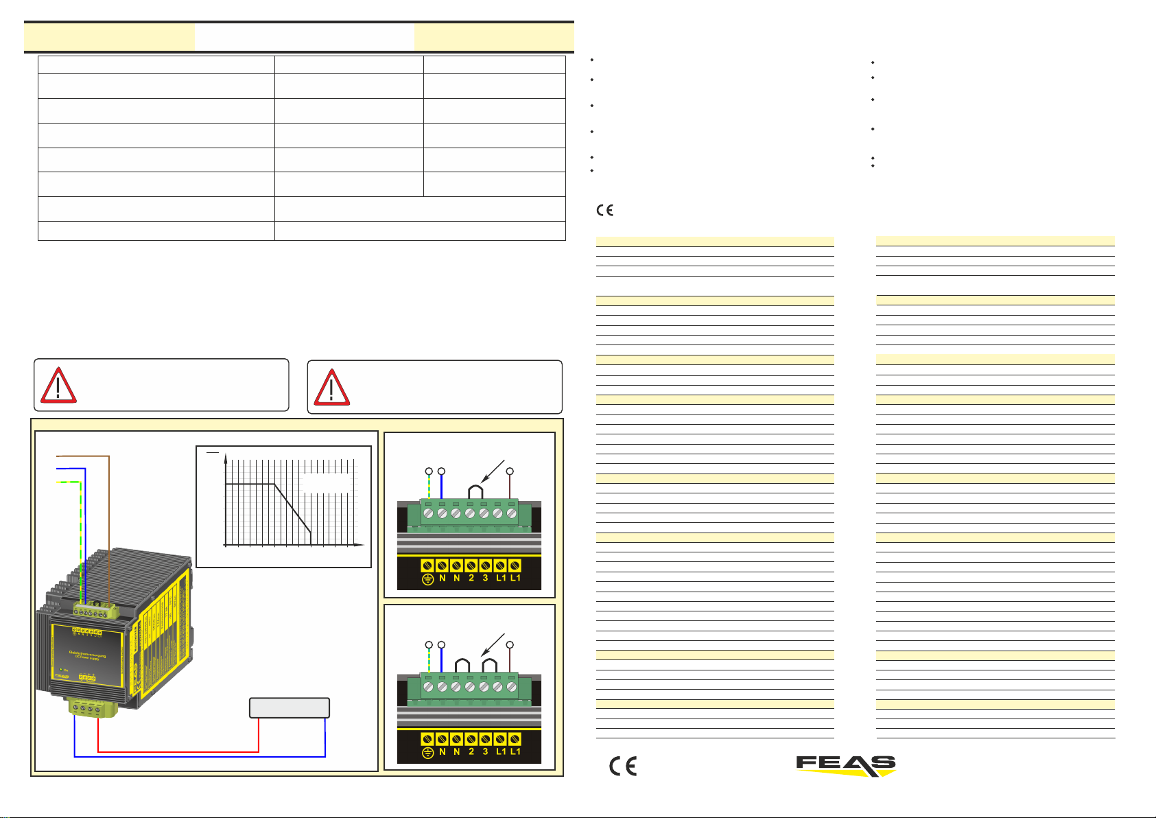
Ausgangsspannung - Output voltage
Typ
Ausgangsleistung - Output-power
Ausgangsstrom - Output current
Wirkungsgrad - Efficiency
Restwelligkeit - Residual ripple (100Hz)
PSW7024
2,5Amp.
77Watt
64%
2,1mV
nominal 24VDCnominal 12VDC
PSW7012
4,0Amp.
72Watt
55%
3,2mV
Maße - Dimensions
Gewicht - Weight ca.2,85kg
BxHxT
WxHxD 95mm x 100mm x 120mm
+
-
Verbraucher
consumer
L1
PE
N
Netzspannung / Line-voltage
Klemmenbelegung / Terminal disposition Klemmenbelegung / Terminal disposition
0,4
0,2
0
0,6
1,0
20100 30 50 70 90 10040 60 80
0,8
1,2
T / C°
Temperatur
Temperature
Ausgangsstrom
Output current
Iout
Inenn
Dauerbetrieb
Current Duty
Technical Data
see table on left side
integrated into the device
from +40°C
EN 60950, EN50081, EN50082, EN55022
Operating data
Starting time
Operating temperature
Temperature coefficient
Efficiency
Derating
Cooling
Safety devices
Output fuse
Overload protection
Hold-up time
MTBF
Safety data
Test voltage transformer
High-voltage resistance
Degree of EMI suppression
Protection class
Ambient humidity
Protective class enclosure
Protective class terminals
Vibration proof
Applied construction regulations
according to VDE
IEC
EN
CSA / UL
Mechanics
Mounting
Dimensions
Weight
100%
-40°C to +70°C
< 500 ppm / K
-40°C...+105°C
selfcooling (S)
not necessary - cont. short-circuit proof
20 msec. typical
> 400.000 h
5 kVac in accordance to VDE 0551
Primary circuit - secondary circuit 4,4 kVac
acc. to VDE 0806 / IEC 380
in acc. to VDE 0871 B, EN 55022/B
Class 1 with PE-connector (EN 60950)
100% rel. humidity, yearly average dewing
allowed for use in tropical ambient
IP 68
IP 20 (VGB4)
>30g at 33Hz in X, Y and Z,
acc. to IEC 68 and DIN 41640
VDE 0100, 0110, 0113, 0551, 0160, 804-8
IEC 60950,IEC61000-6-1-2-3-4,IEC60068-2-3
CSA-C 22.2 / UL60950, UL508, UL1950
On DIN-Rail or With screws
none
1.5xINominal
Input data
Input voltage
Input current at nominal load
Output voltage U
Rang of adjustment
Output current
Start of current limiting
Residual ripple (100Hz)
nomnal
PSW: 115 VAC or 230 VAC
45 - 66 Hz
-10% and +10%
see table on left side
see table on left side
see table on left side
see table on left side
< 200mV with load variation 10...90%
< 50 µsec. with load variation 10...90%
Control data
Control deviation load
Control deviation supply
Control time < 10mV with supply variation ±10%
Frequency
Input voltage tolerance
Storage temperature range
Fuse recomended for input
95mm x 100mm x 120mm (W x H x D)
approx. 2,85 kg
at 115V max. 1.5 Amp.
at 230V max. 0.75 Amp.
Output data
Derating
PSW70
- konform GmbH Postfach 1521
D - 22905 AHRENSBURG Telefon: 04102 - 42082
Telefax: 04102 - 40930
www.feas.de
©2017 ®
Vorsicherung - träge
Fuse for input - delayed
bei 230VAC 1,5Amp.
at 230VAC 1,5Amp.
bei 115VAC 3,0Amp.
at 115VAC 3,0Amp.
Eingang - Input 230VAC
Eingang - Input 115VAC
Brücke
connection
Brücken
connections
GmbH Postfach 1521
D - 22905 AHRENSBURG
Telefon: 04102 - 42082
Telefax: 04102 - 40930
www.feas.de
© 2012 ®
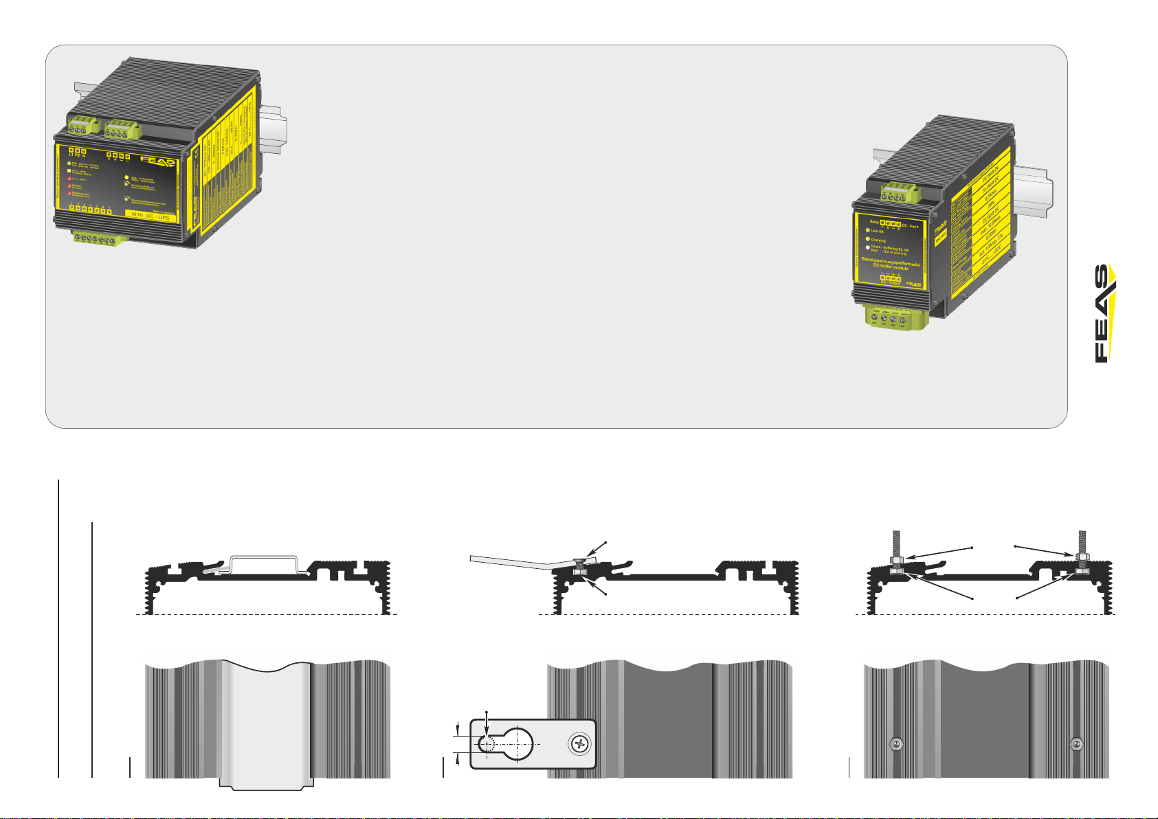
Befestigung Alternativen.
Mounting alternatives
1.
2.
3.
Geeignet für M6
Schrauben
Suitable for
M6 screws
6,1 mm
Hutschiene
rail
Mutter M3
Nut M3
Schraube M3x6
Screw M3x6
Mutter M3
Nut M3
Schraube M3
Screw M3
SSE2405
Puffermodul
Art.Nr.: 622405
Ÿ Gleichspannungspuffermodul für 24 VDC Netz
Ÿ Sicherheitskleinspannung
Ÿ Überlast- und Leerlaufsicher
Ÿ Kurzschlussfest
Ÿ Parallelschaltbar
Ÿ Keine Akkus verbaut - wartungsfrei
Ÿ LED-Betriebsanzeige
Ÿ Relais für Fernüberwachung der
Spannungsversorgung
Ÿ Tropentauglich durch Gießharzvollverguss
Ÿ Sicherheit nach VDE, EN, UL CSA
Technische Daten:
Eingang (VDC): 23,5 - 31,0 VDC
Ladestrom: 0,3 A
Pufferspannung: 22,5 VDC
max. Ausgangsstrom: 10,0 Amp.
Restwelligkeit: < 25 mVSS
Arbeitstemperatur: -30°C bis +70°C
Montage: auf Hutschiene nach DIN 46277 und Wandmontage
Abmaße (BxHxT): 64,0 x 100,0 x 120,0 mm
Gewicht: 1,25 kg
LDR30MH24
Mini DC-USV für die Hutschiene
Art.Nr.: 589960
Ÿ3 in 1, vereint Schaltnetzteil, Ladekontrolleinheit und Akku in
einem sehr kompakten Gehäuse
ŸPufferung eines Verbrauchers bei Netzausfall
ŸPufferzeit begrenzbar (1-20 Minuten und unbegrenzt)
ŸIm Pufferbetrieb manuell abschaltbar, “Schlafenlegen”
ŸIntegrierter NiMH Akkumulator mit 0,72 Ah (austauschbar)
ŸMikroprozessorgesteuerte Akkumulator-Überwachung und
Ladeanzeige
ŸLED-Anzeigen für Netzausfall, Überlast und Übertemperatur
ŸRelais-Meldung von Netzausfall, Übertemperatur, Akku-
Defekt und Akkuspannung kritisch
ŸBoostfunktion: 150% Iout bis zu 30s
ŸKurzschlussfest, überlast- und leerlaufsicher
ŸAusgang potentialfrei nach VDE 0551
ŸSicherheit nach VDE, EN, UL und CSA
Technische Daten:
Eingang: 85-270 VAC (0-400 Hz) / 120-380 VDC
Ausgangsspannung: 24 VDC (22,5 VDC - 29,5 VDC)
Ausgangsstrom: 2,0 A (3,0 A Boost)
Kapazität: 0,72 Ah
Leistung: 48,0 Watt
Wirkungsgrad: ca. 91%
Restwelligkeit: < 50 mVSS
Arbeitstemperatur: -20°C / +70°C
Montage: auf Hutschiene nach DIN 46277
Abmaße (BxHxT): 108,0 x 100,0 x 120,0 mm
Gewicht: 2,30 kg
This manual suits for next models
1
Other FEAS Power Supply manuals


Popular Power Supply manuals by other brands

Lambda
Lambda ESKI instruction manual

Keithley
Keithley 242 instruction manual

STATRON
STATRON 3231.10 manual

Rockwell Automation
Rockwell Automation Allen-Bradley 1606-XLE240EDRZ SER B installation instructions

Omron
Omron S8JX-P300 Series instruction manual

SIIG
SIIG A/V PowerSaver Pro Quick installation guide


